Arduino Enigma
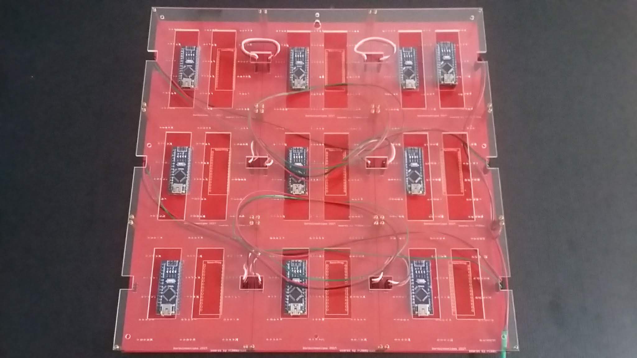
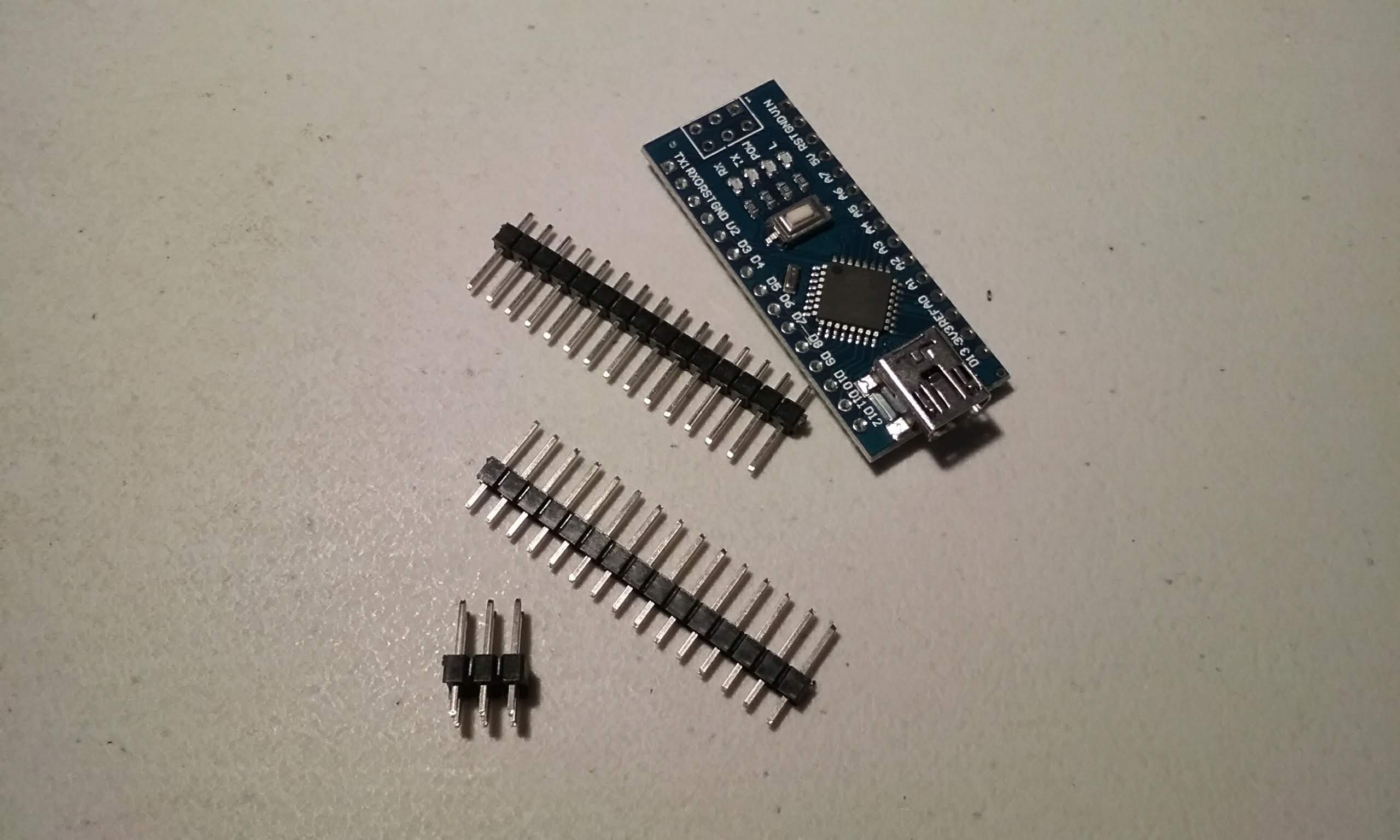
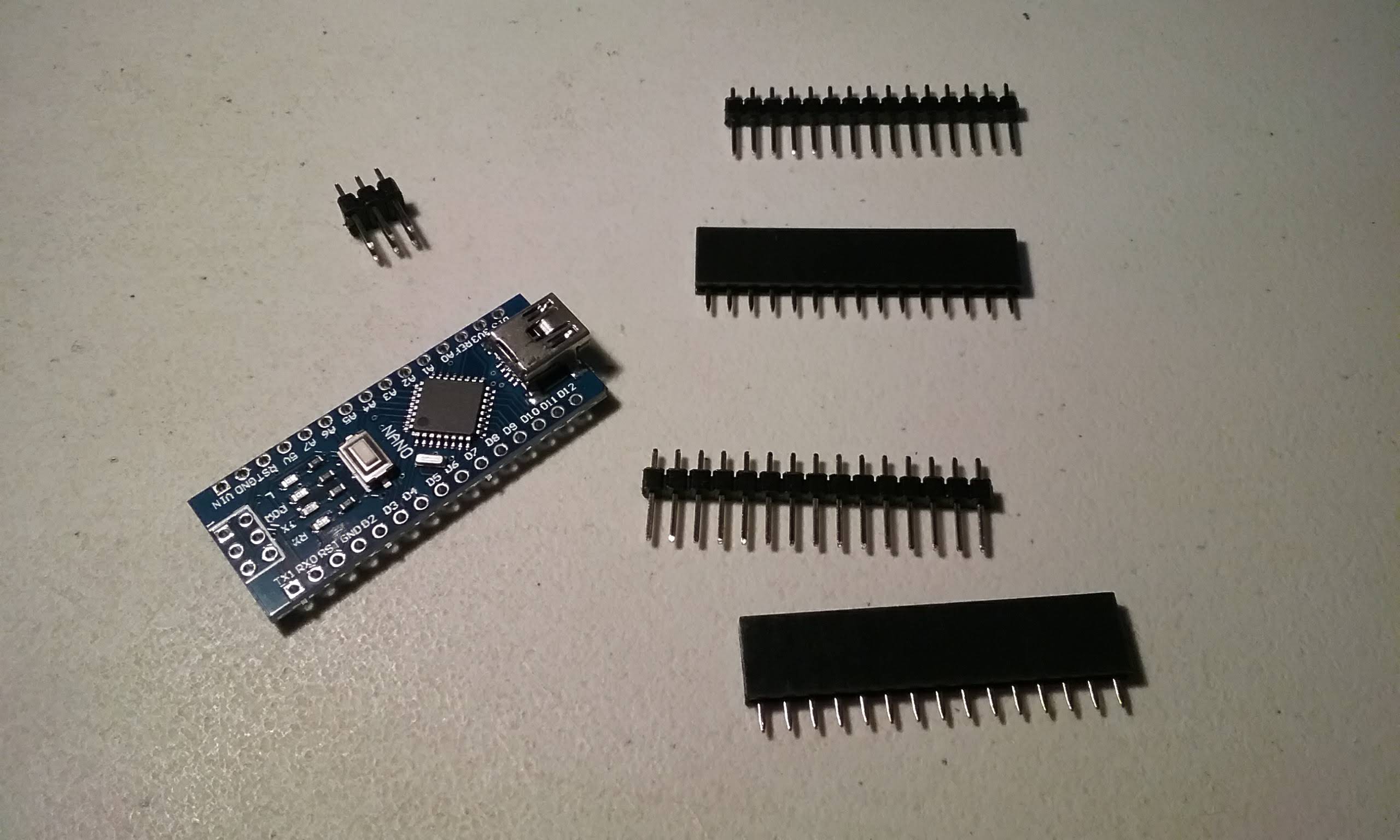
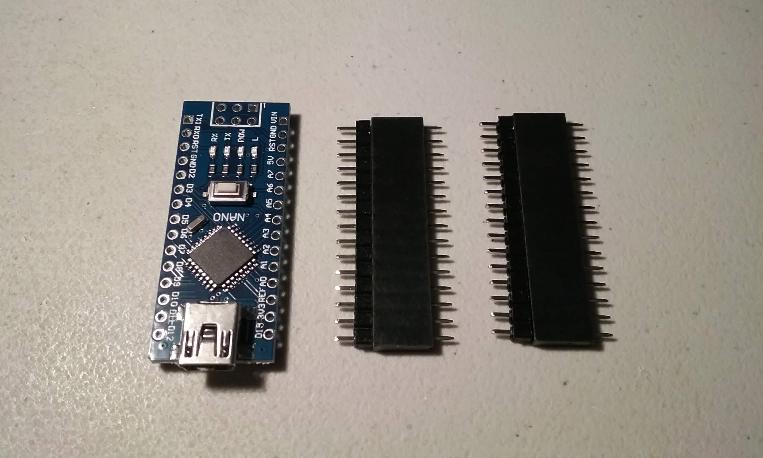
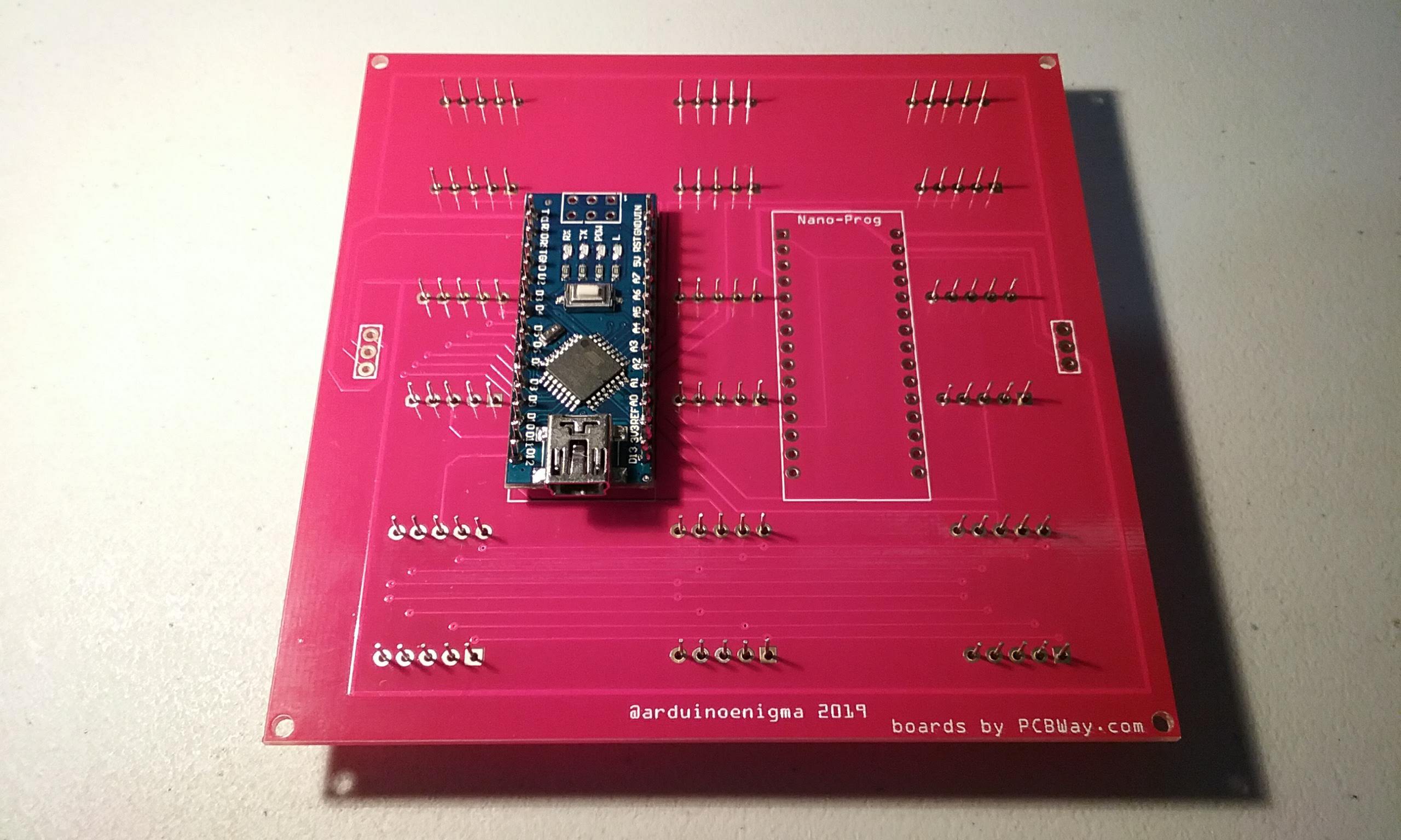
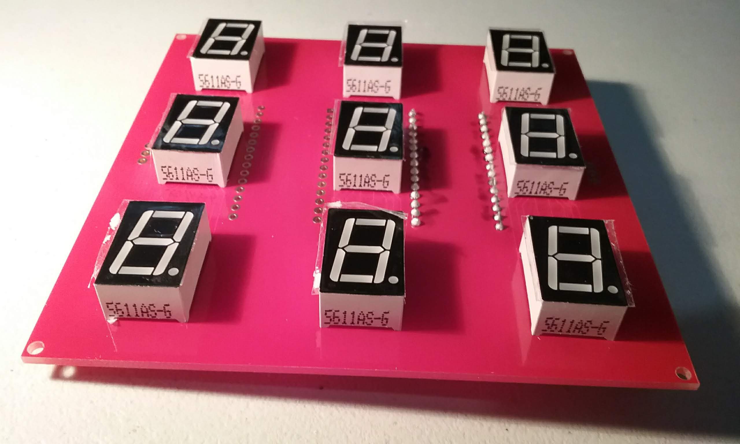
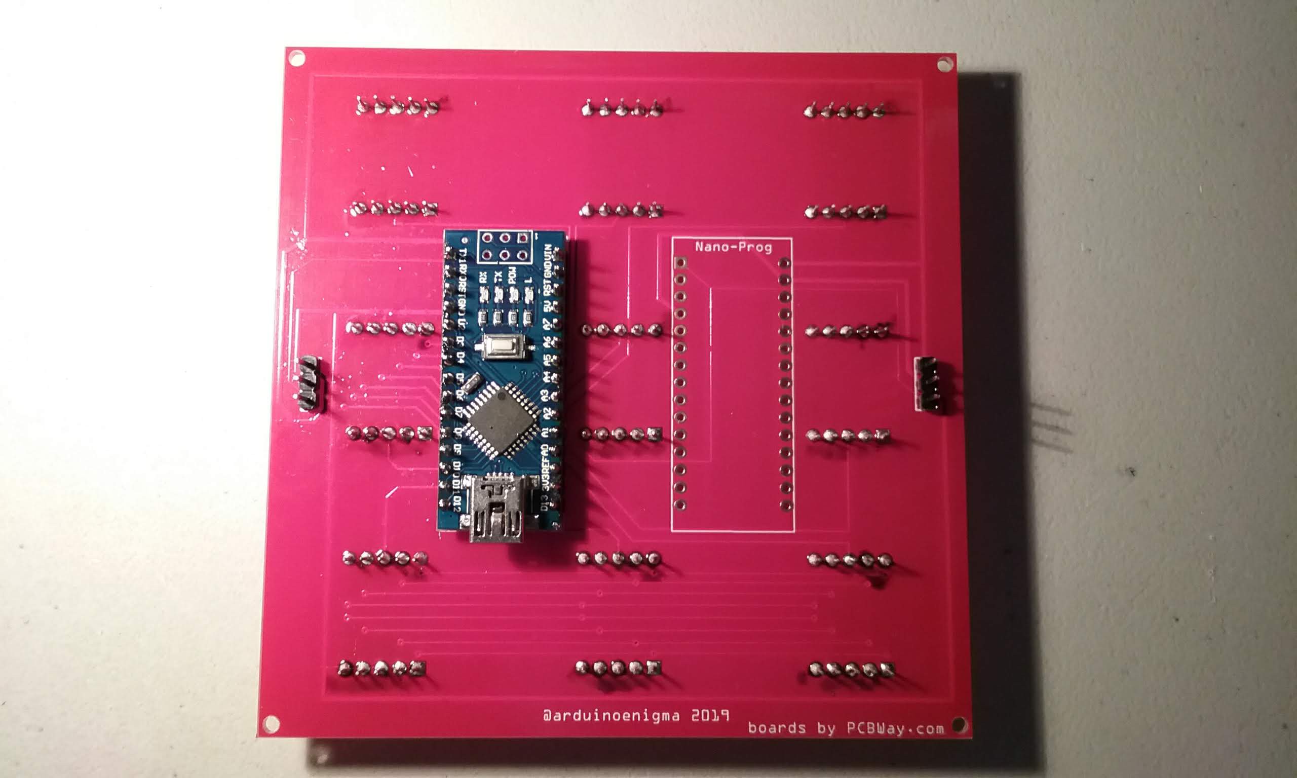
The idea here was to make a large animated seven segment display the simplest way possible, its just a board with an Arduino Nano, some seven segment displays and two headers. That's it.
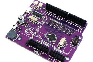
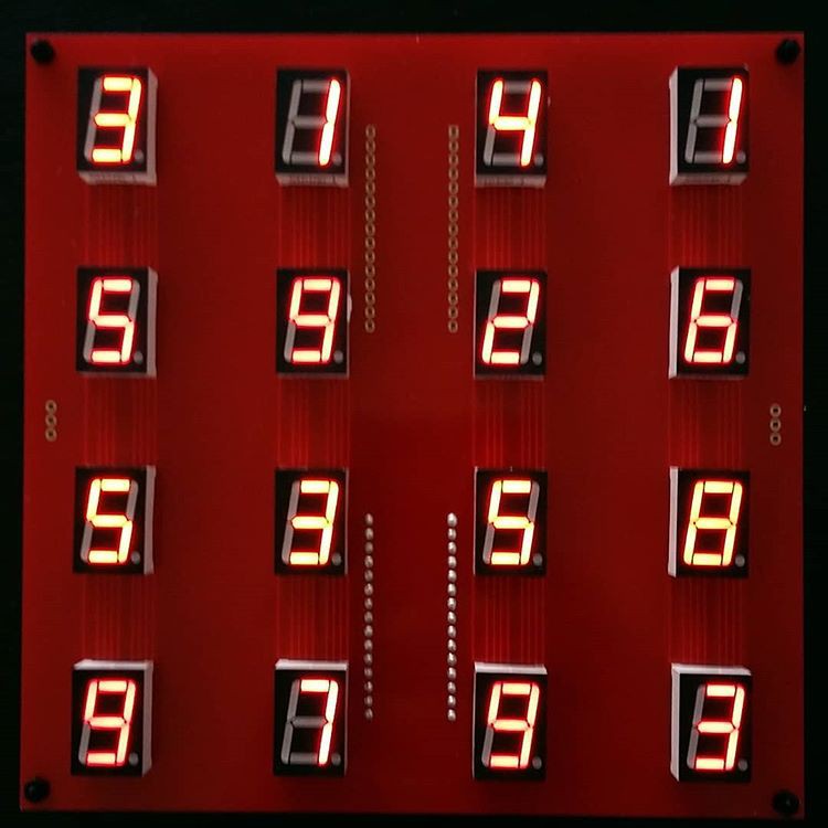
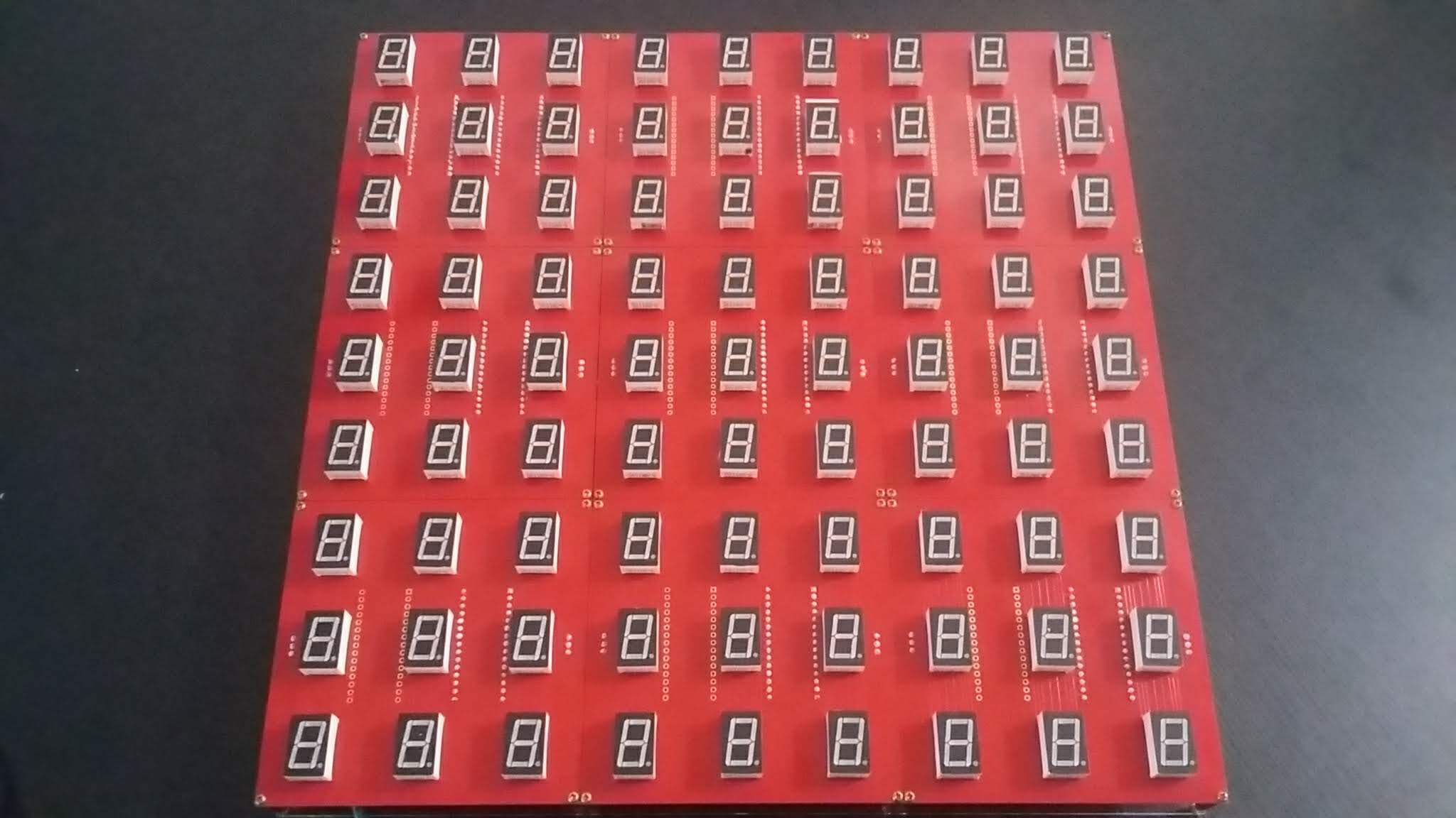
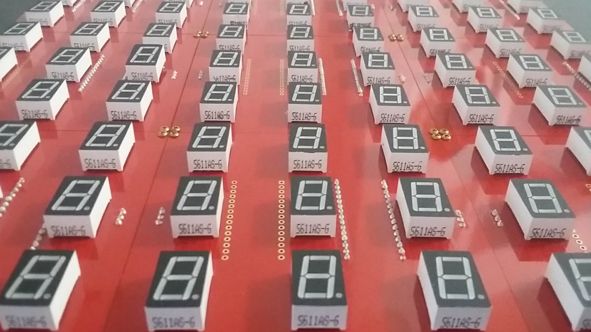
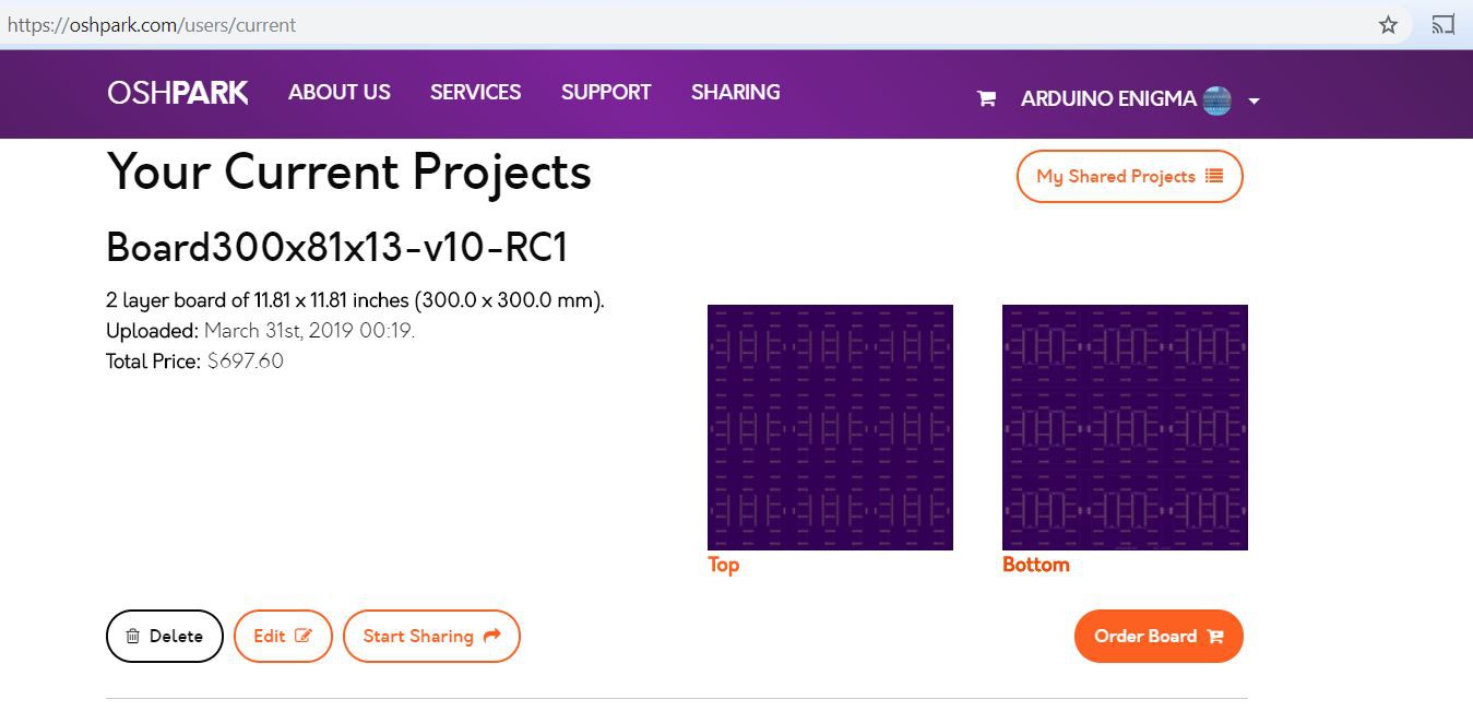
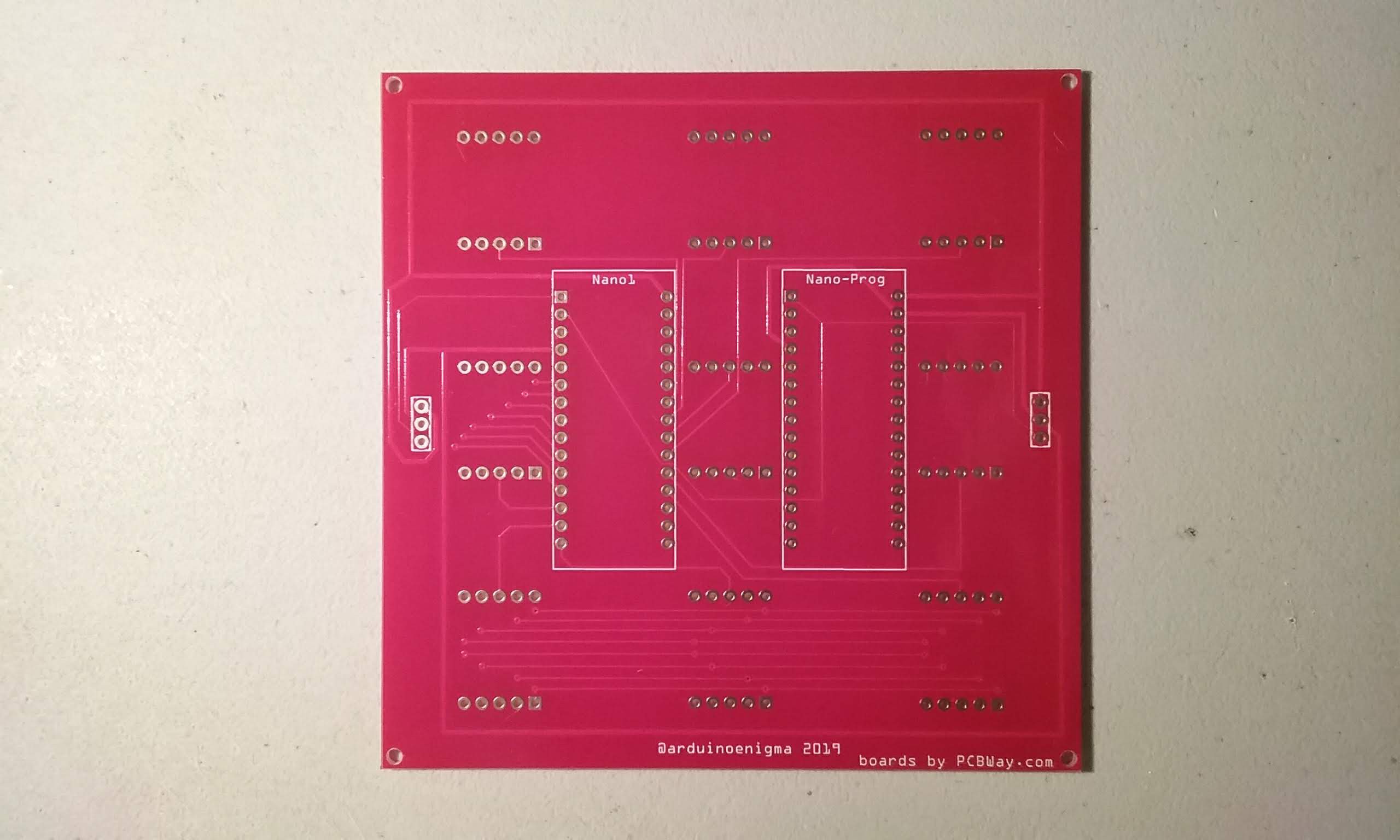
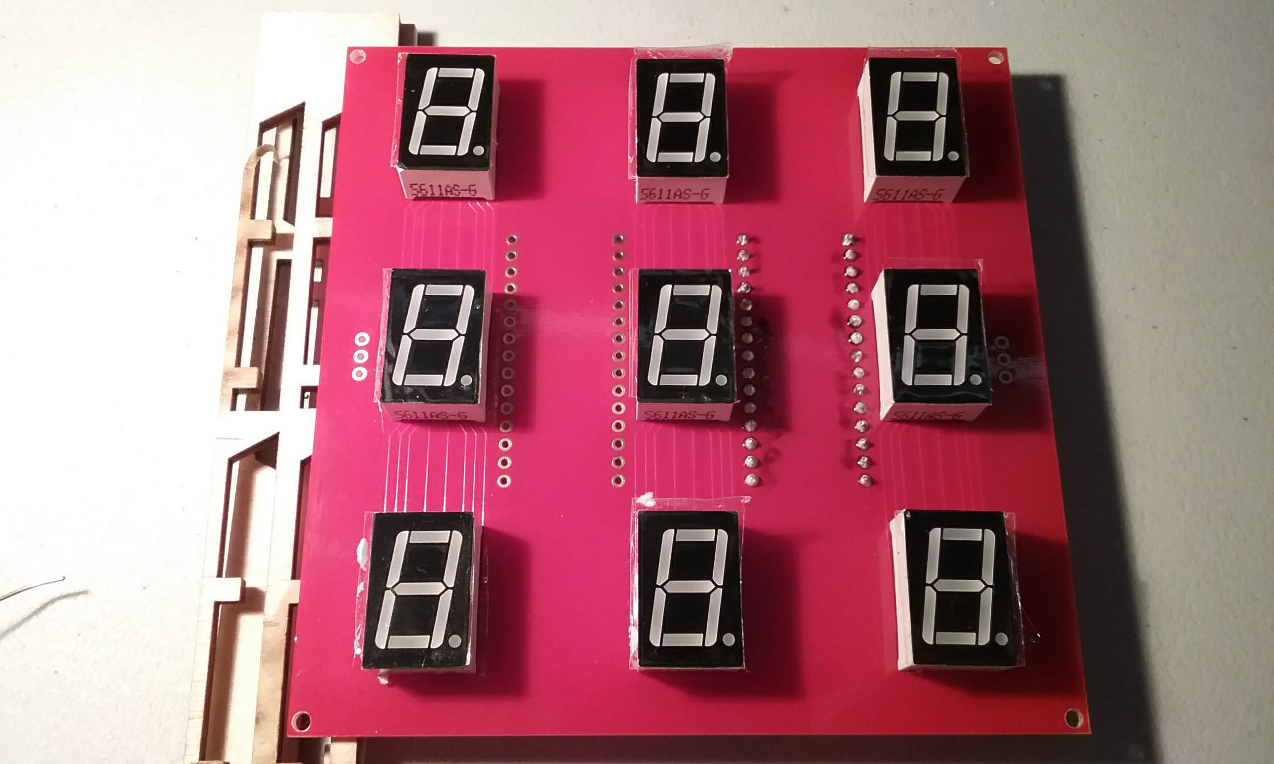
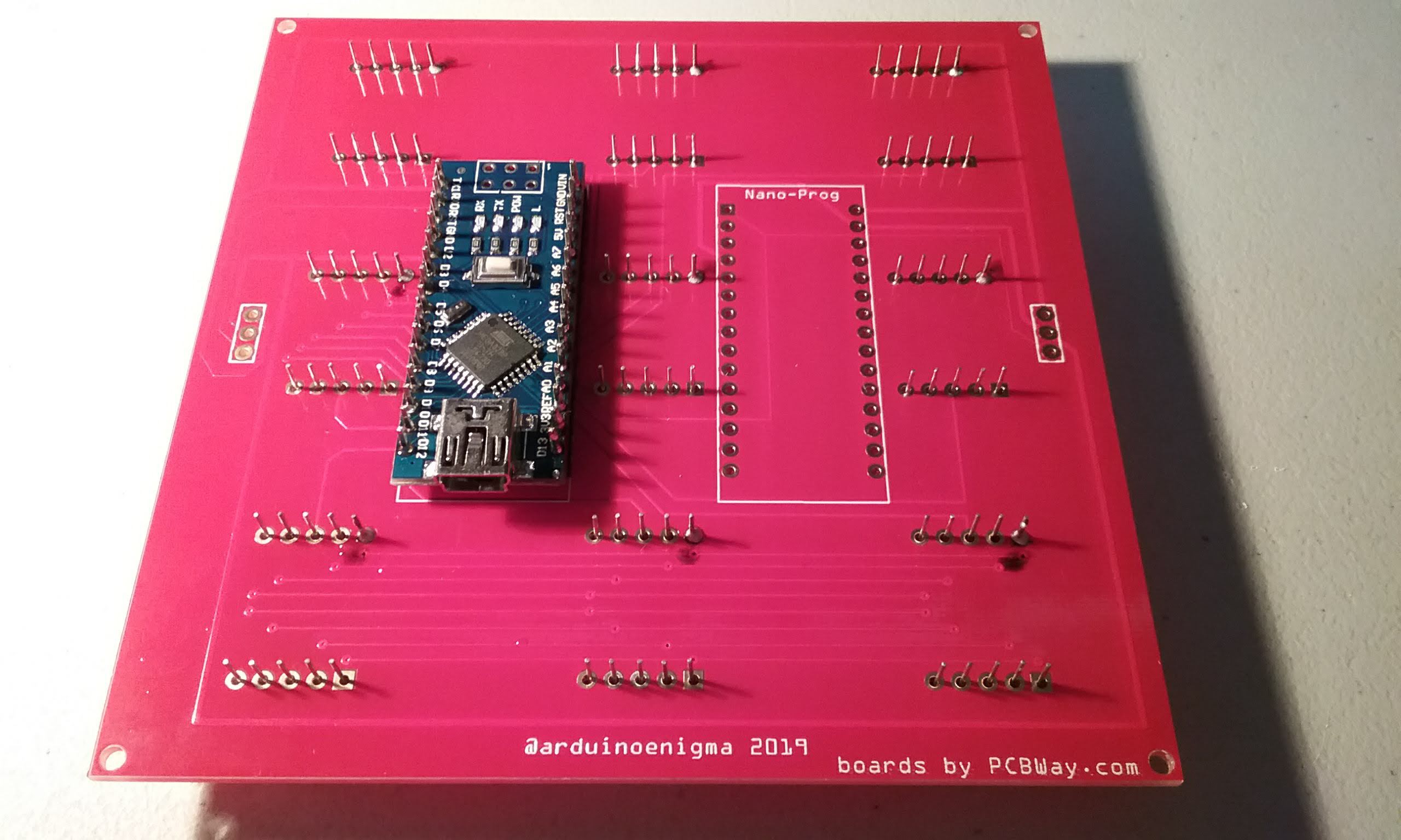
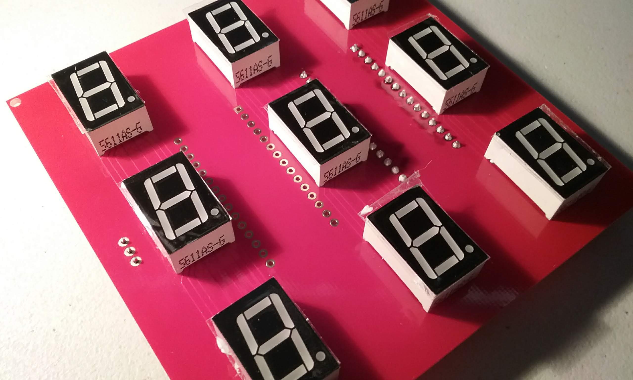
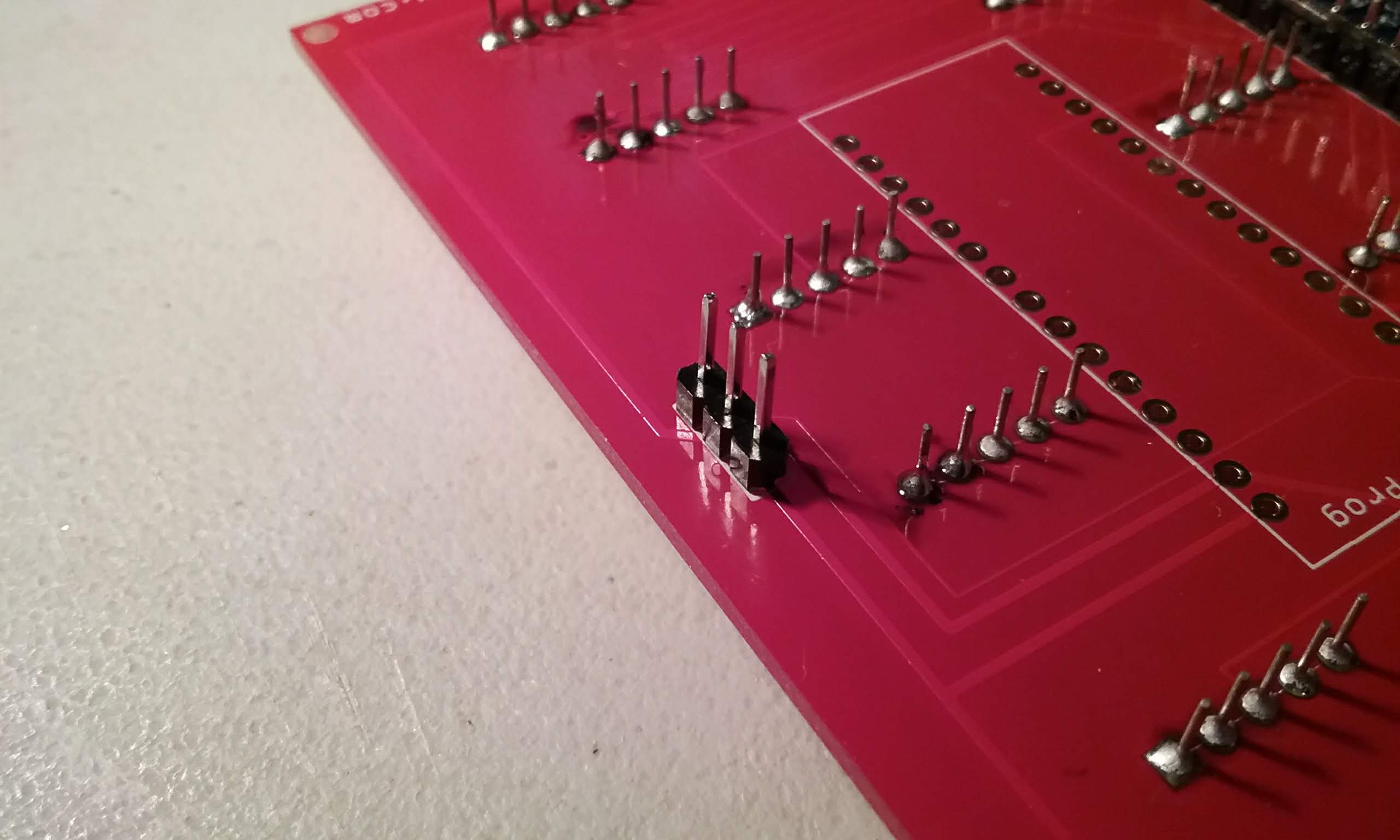
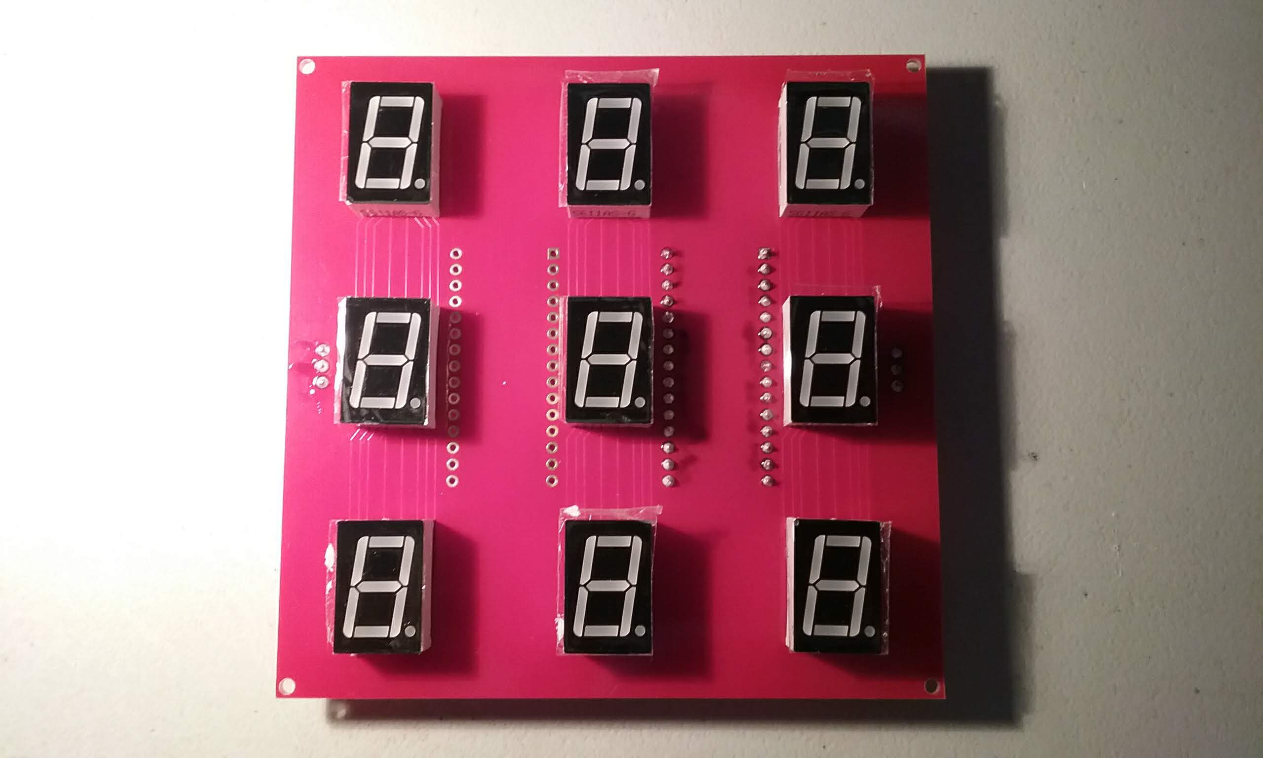
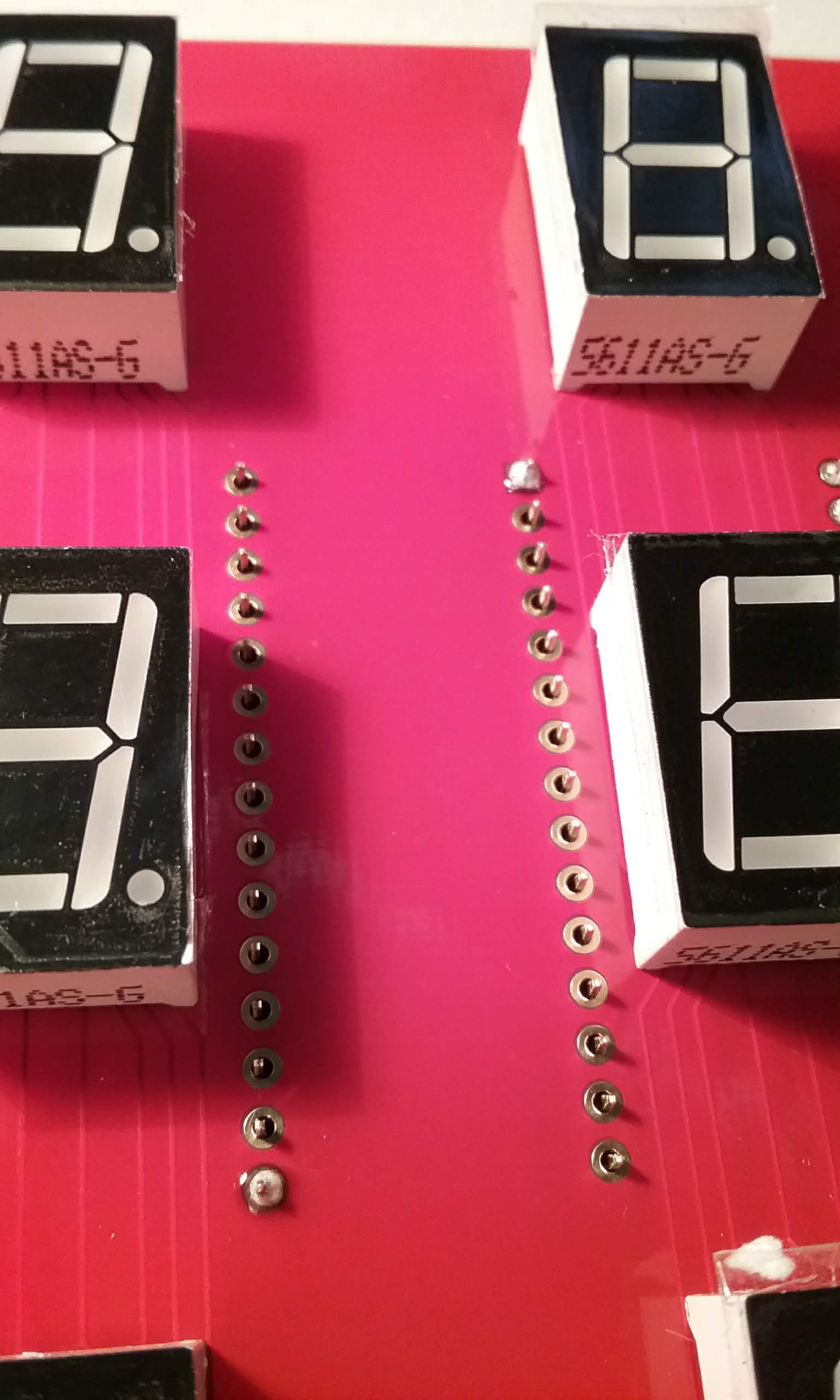
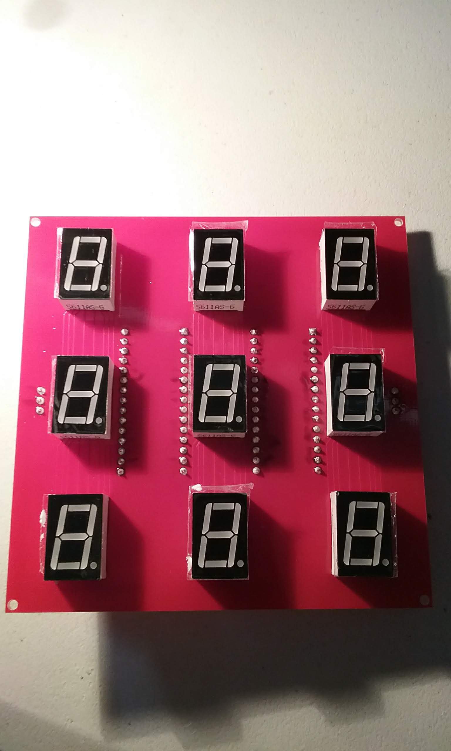
This project starts with a board size that can be manufactured cheaply (100mm x 100mm). In this board we can fit 9 (0.56") seven segment displays.
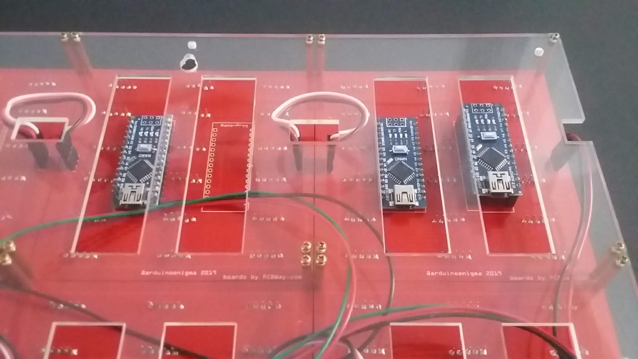
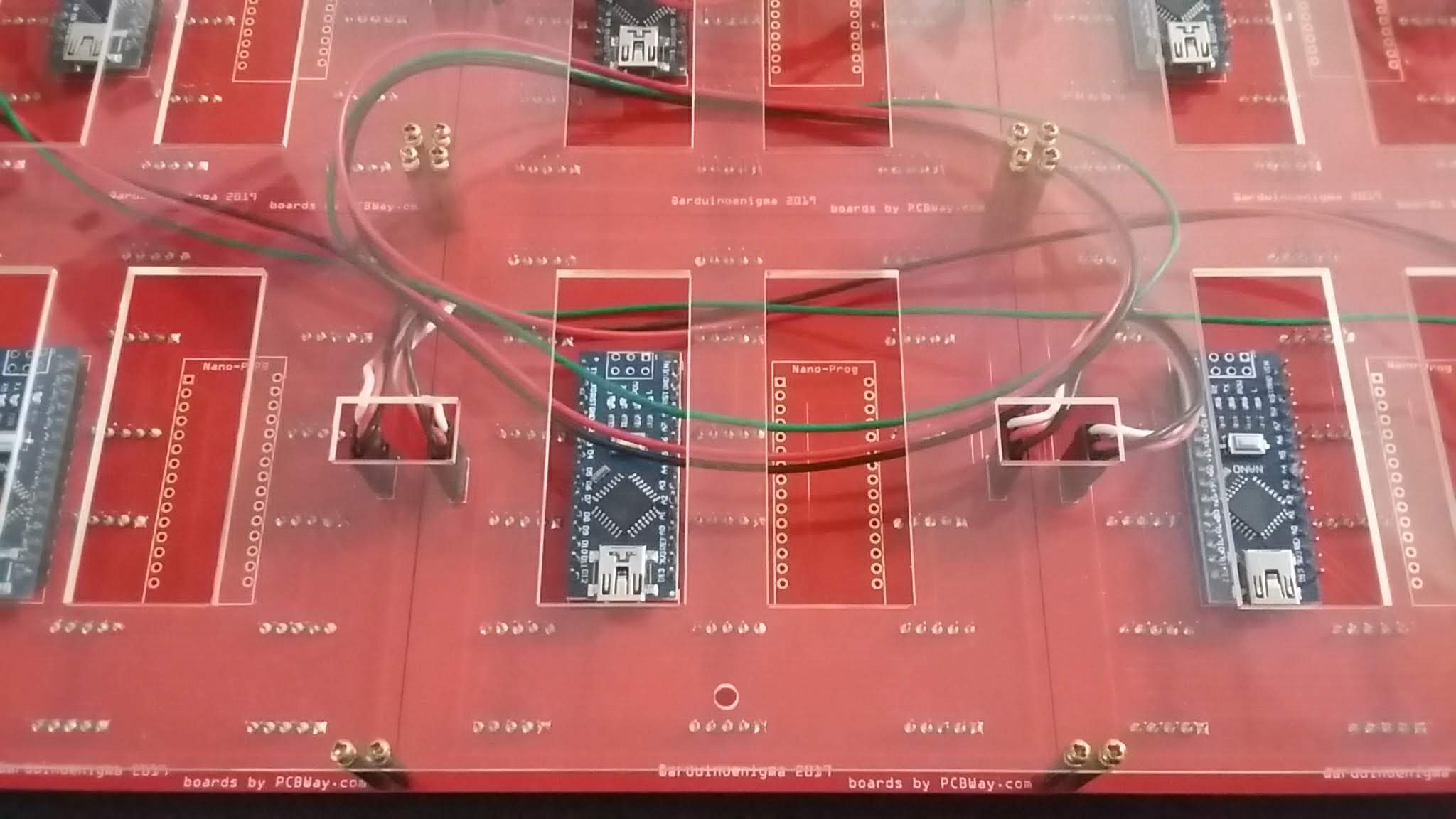
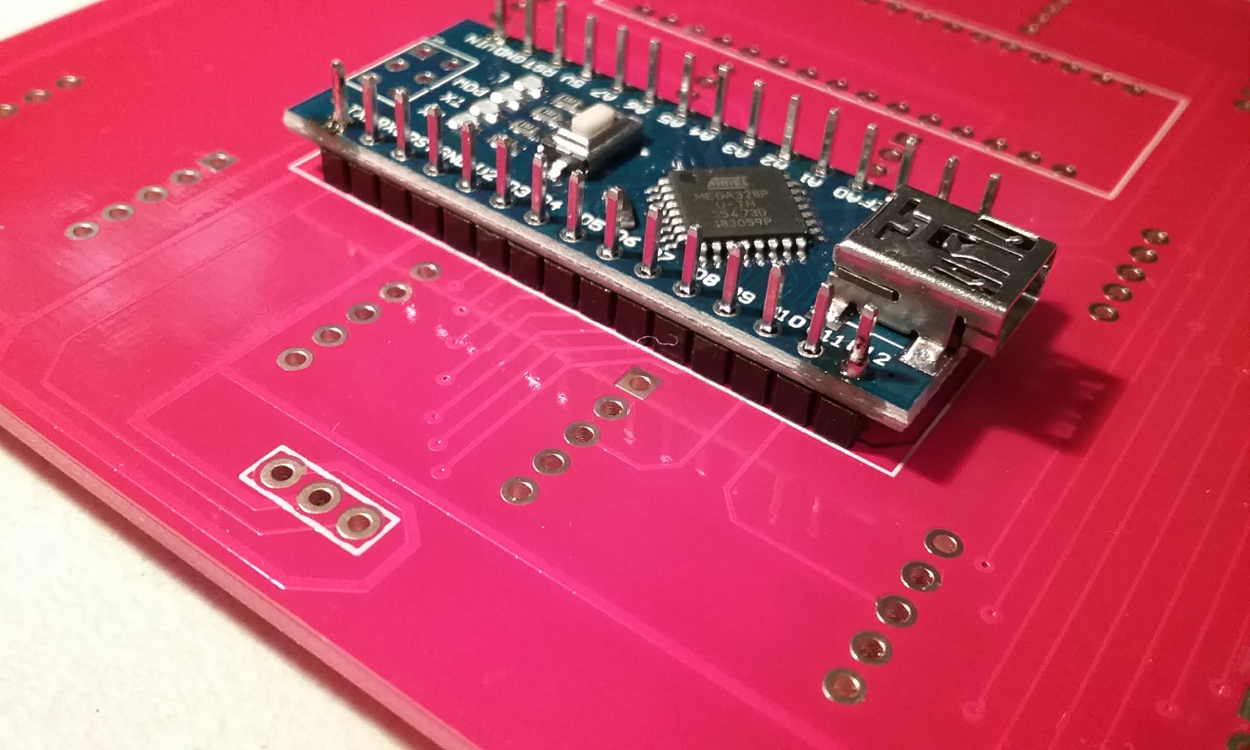
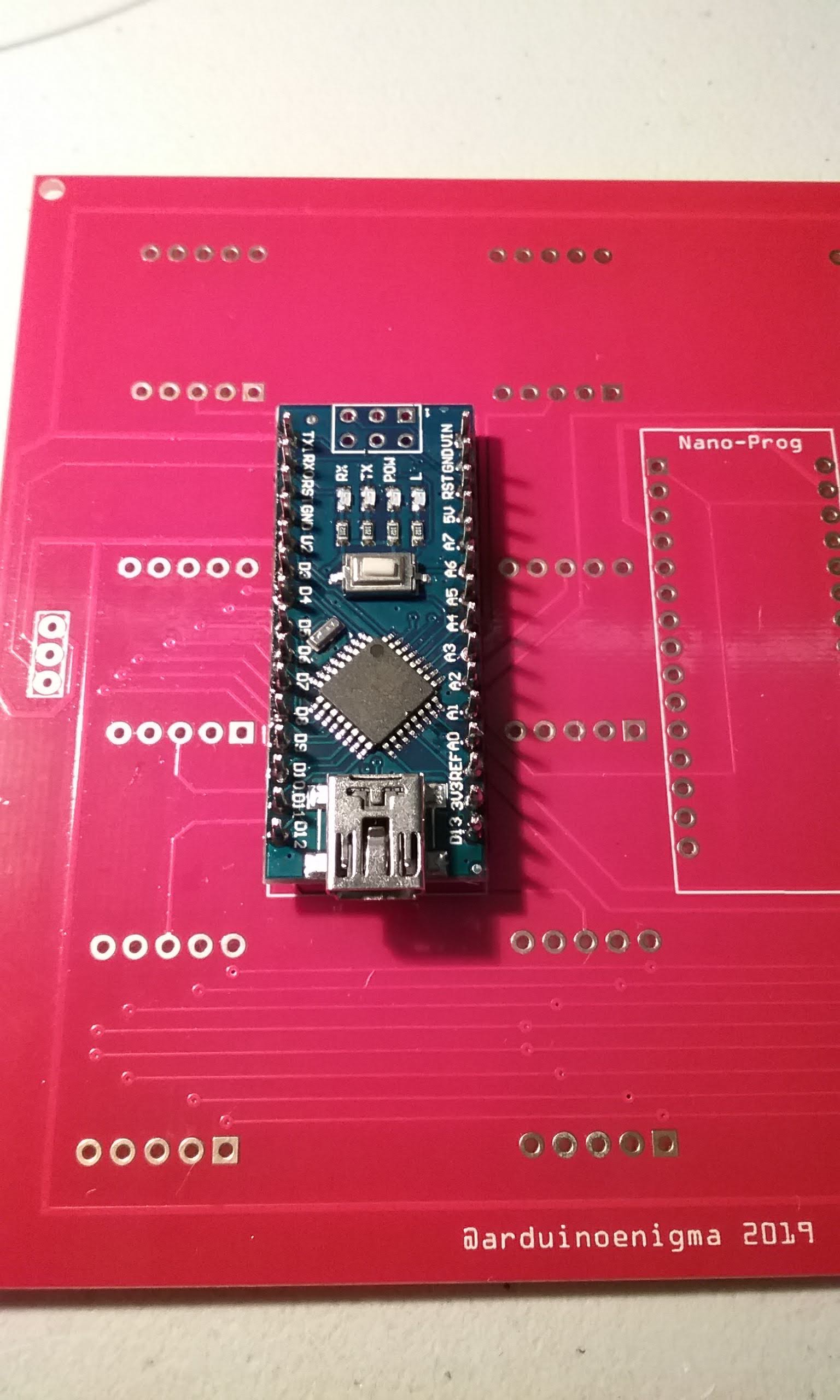
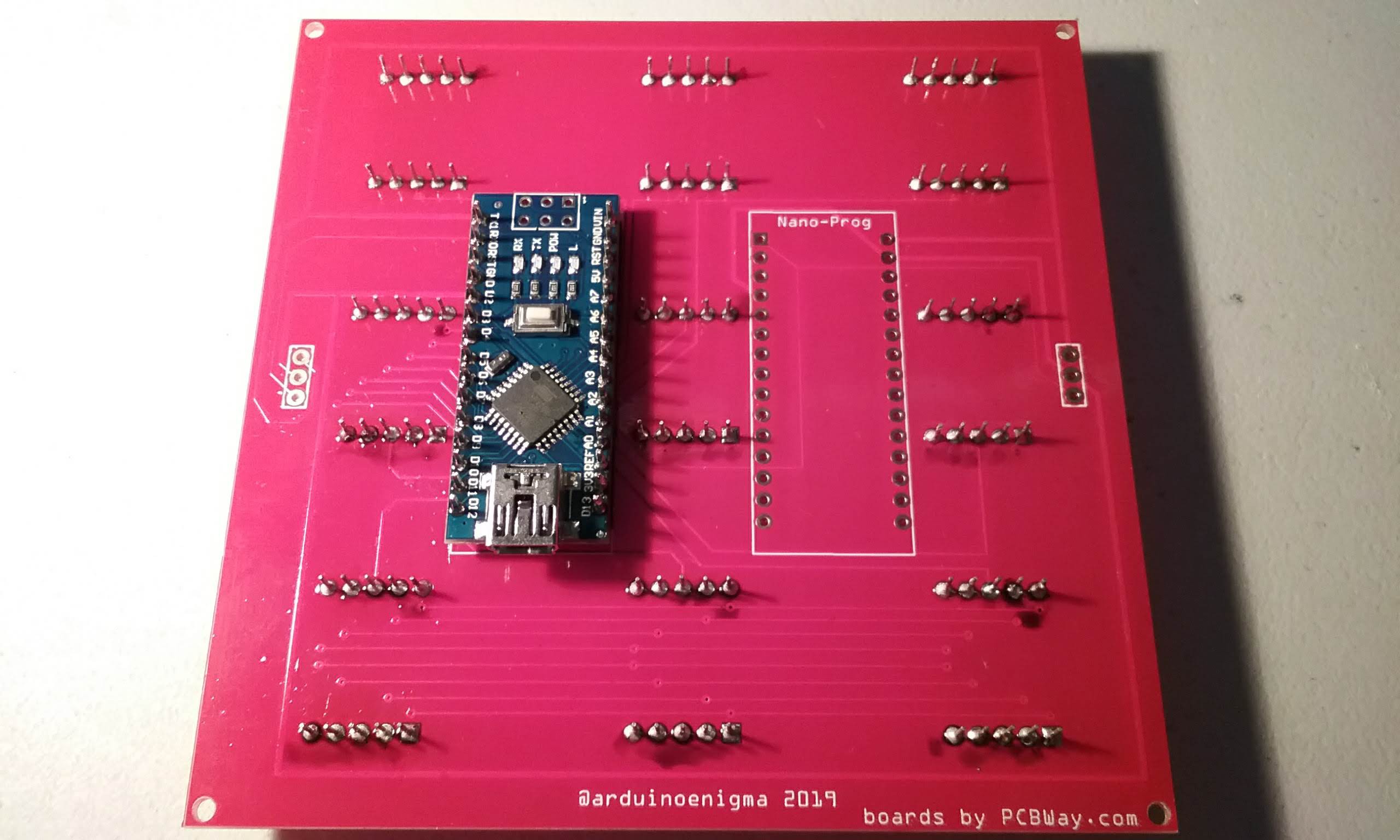
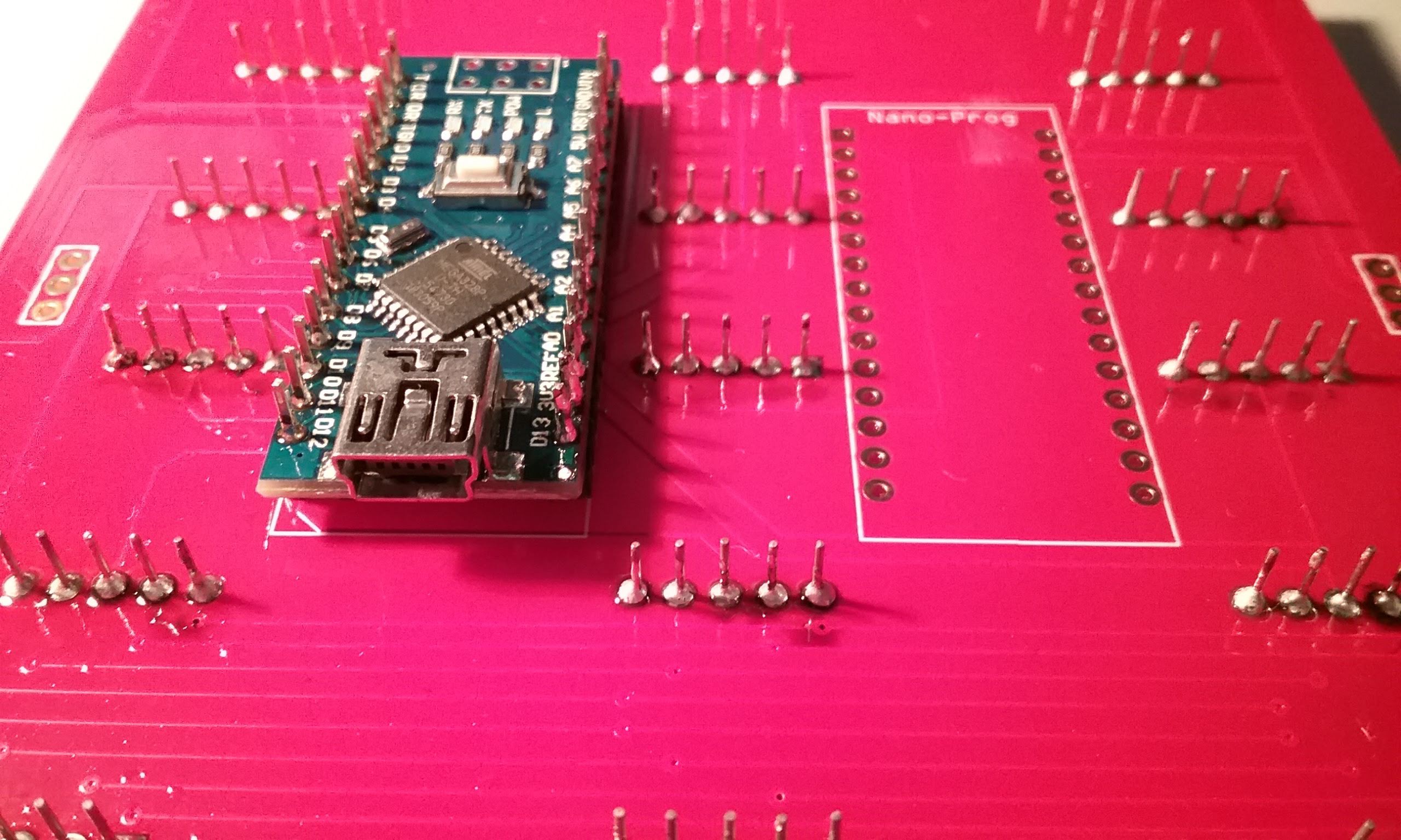
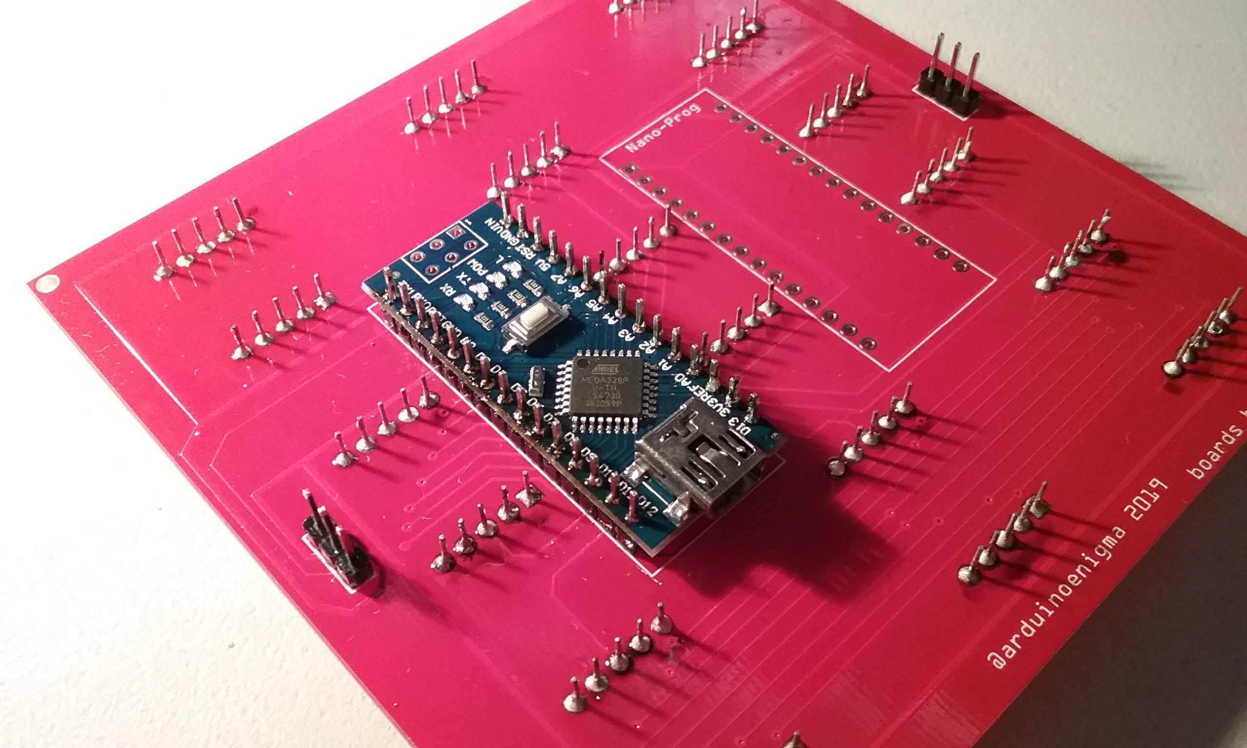
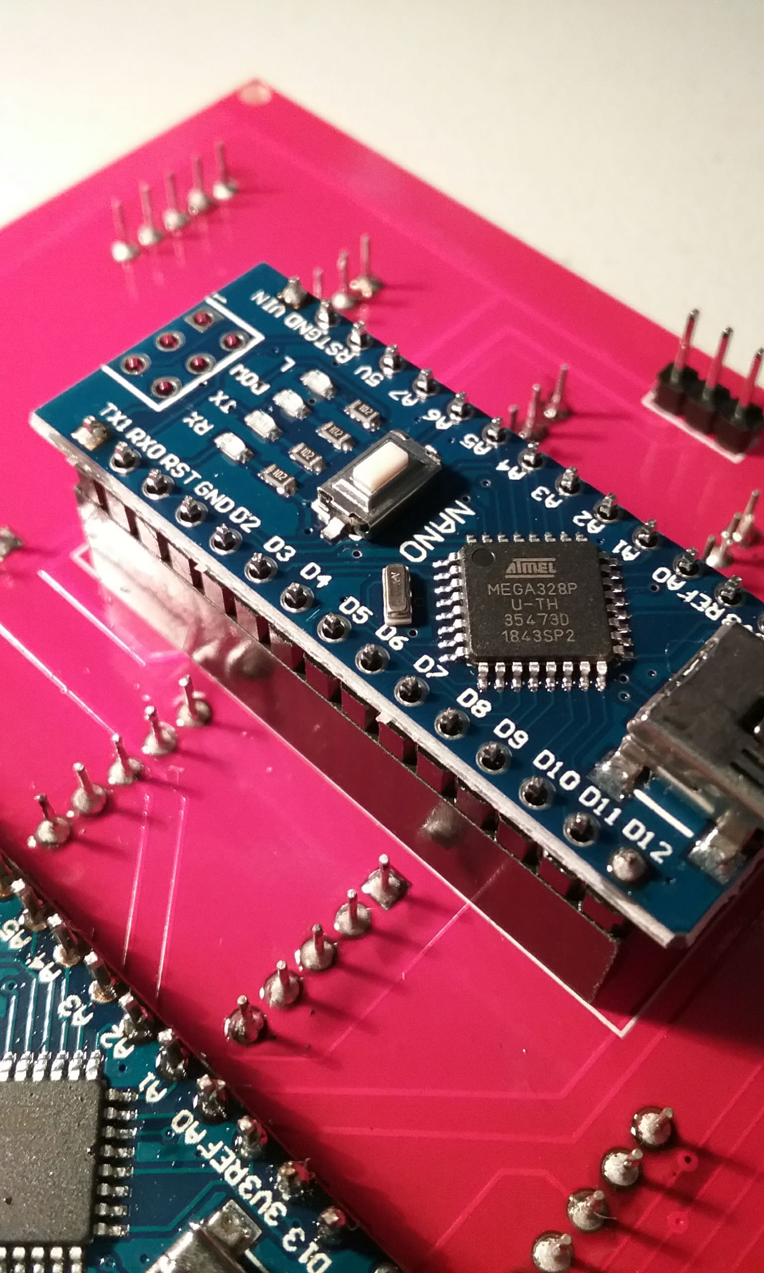
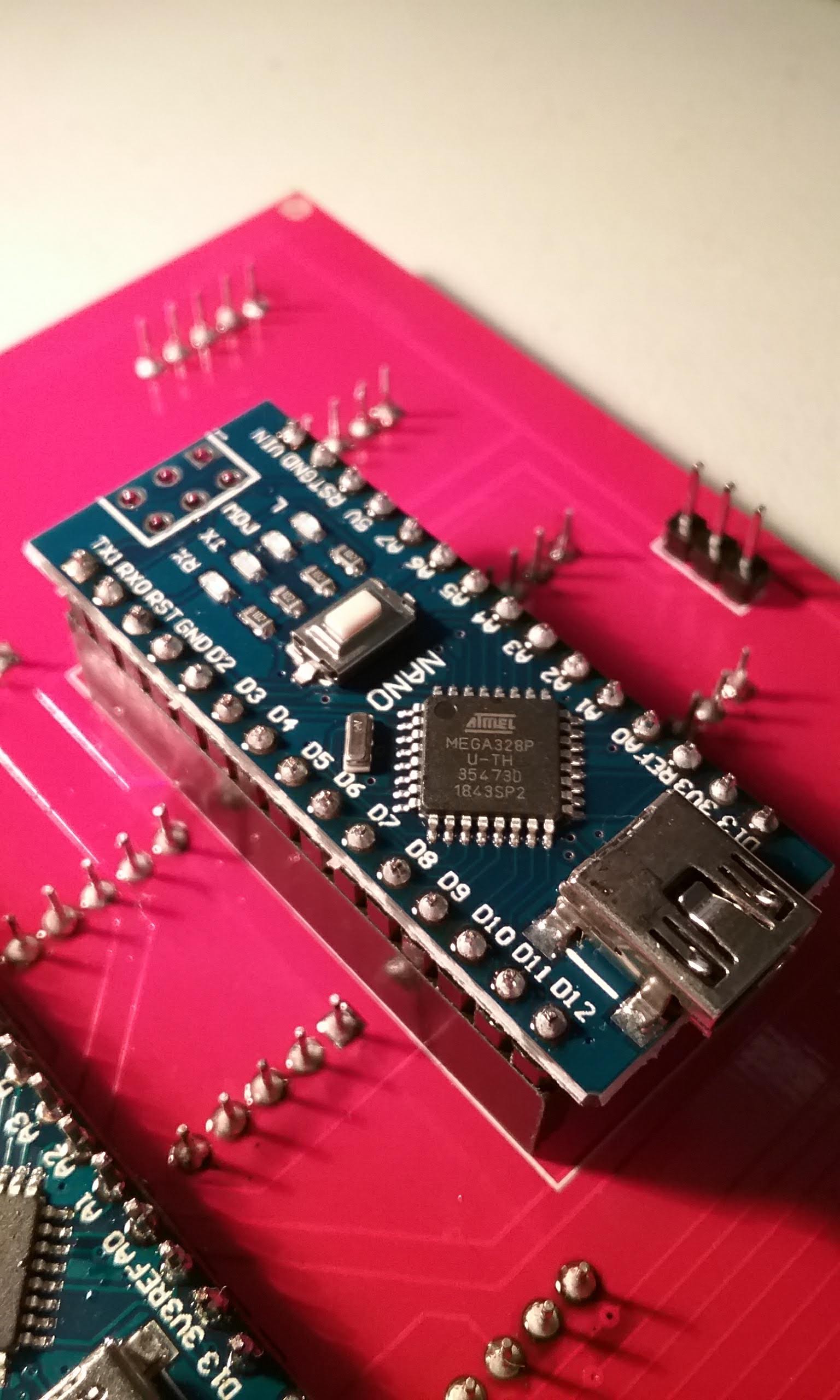
An Arduino Nano can directly drive up to 12 seven segment displays in a multiplexed arrangement. In this project we only drive 9 and keep D13 with its built in LED and the serial port pins free. The Arduino in each tile is also responsible for receiving commands from the previous tile and relaying commands to the next tile.
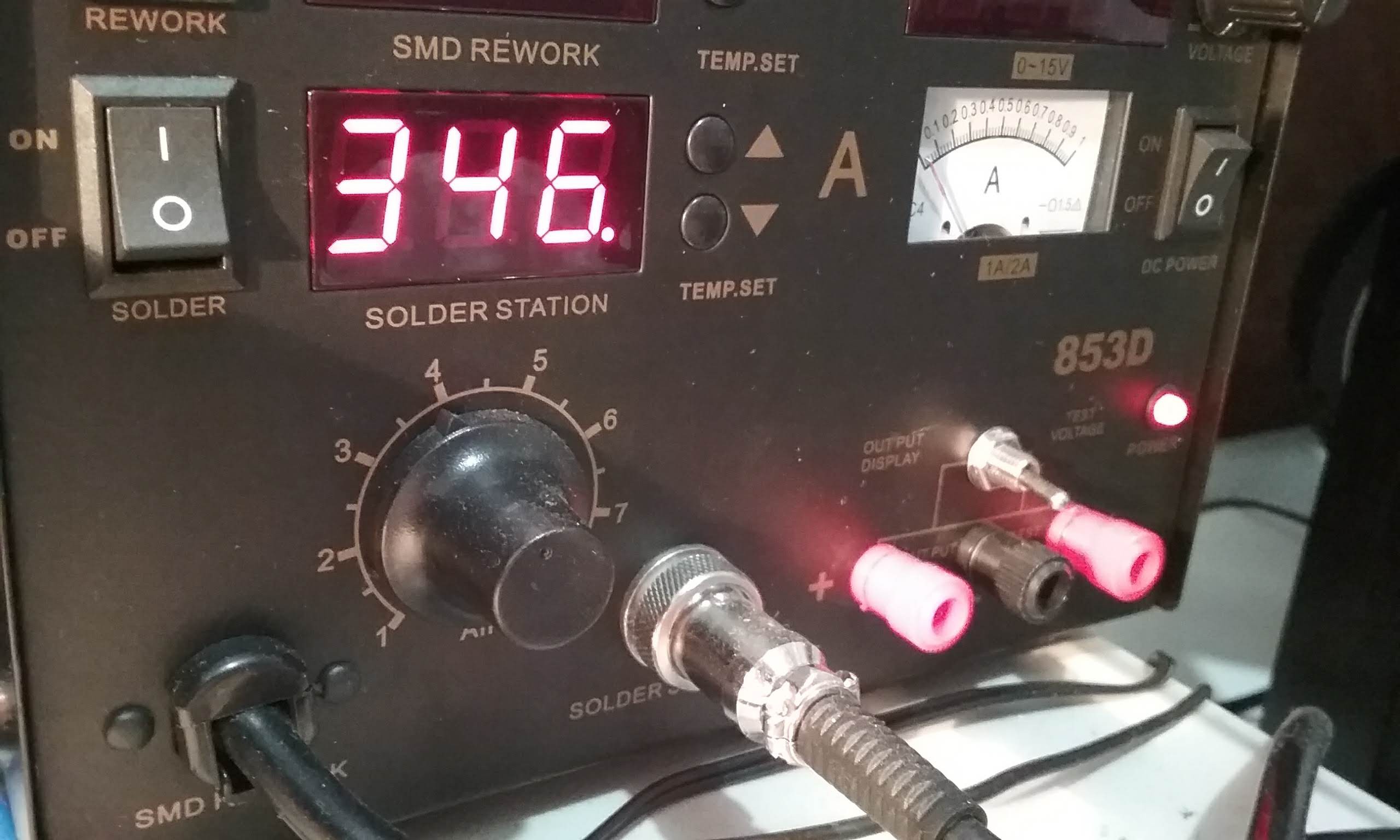
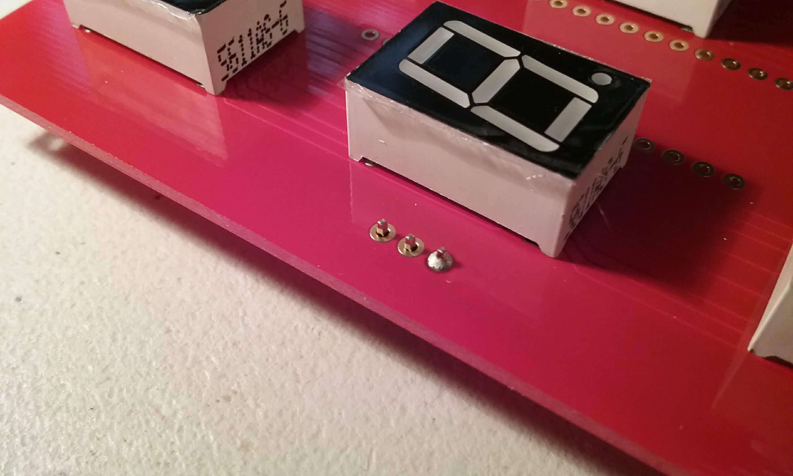
Current limiting is done in software, to keep things simple, there are no resistors on the boards. Development is done in a Sinclair Scientific Calculator and the sketch is uploaded to the tiles once it is working properly. Each digit is turned on for up to 255 uS and then the next digit is turned on. Each digit has 2ms to cool down. When powered with a wall adapter, it is quite bright.
The idea for the software current limiting came from using a Bubble LED displays on the Sinclair Scientific Calculator. The only way to get decent brightness out of them was to eliminate the current limiting resistors altogether and instead control the current via the duty cycle.
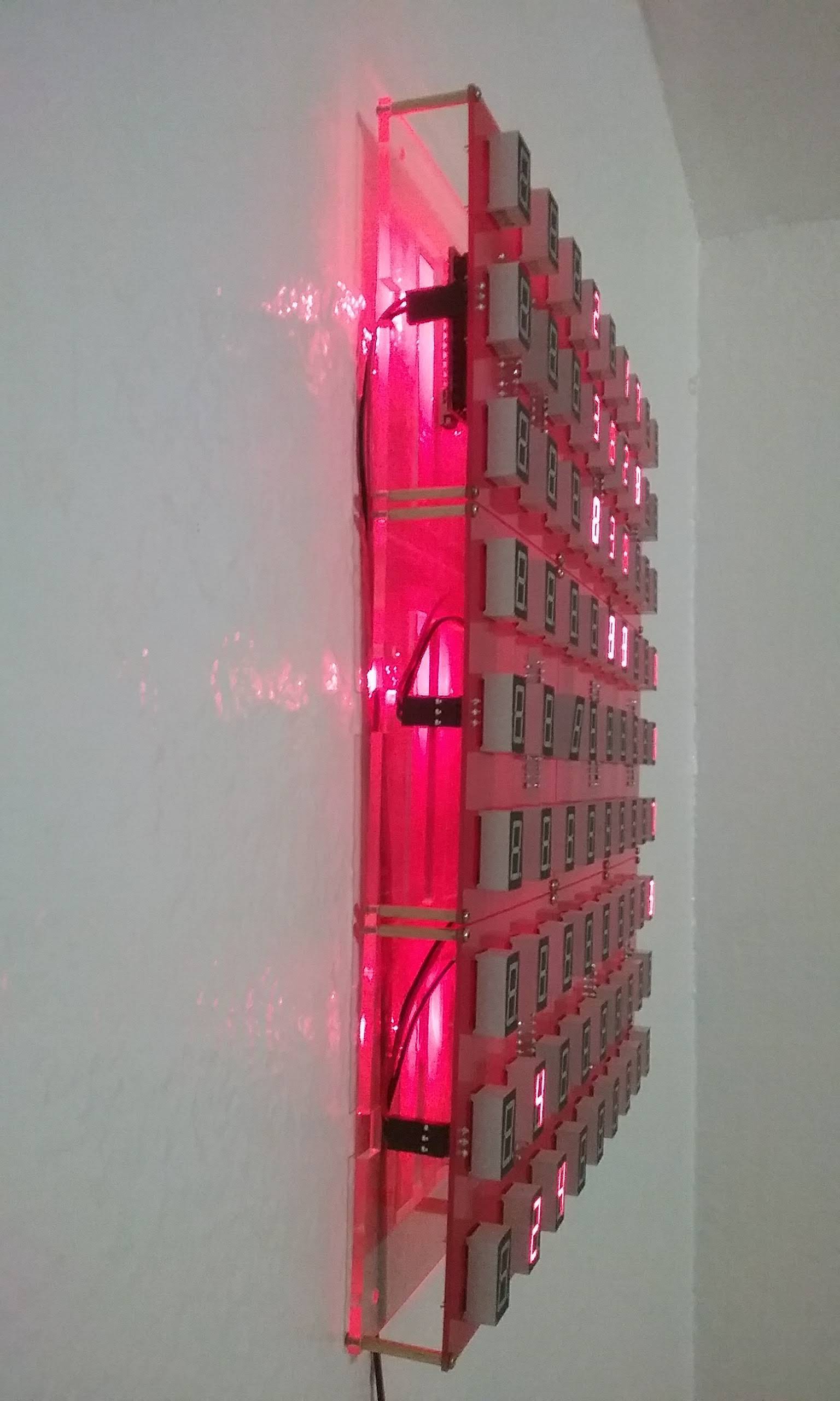
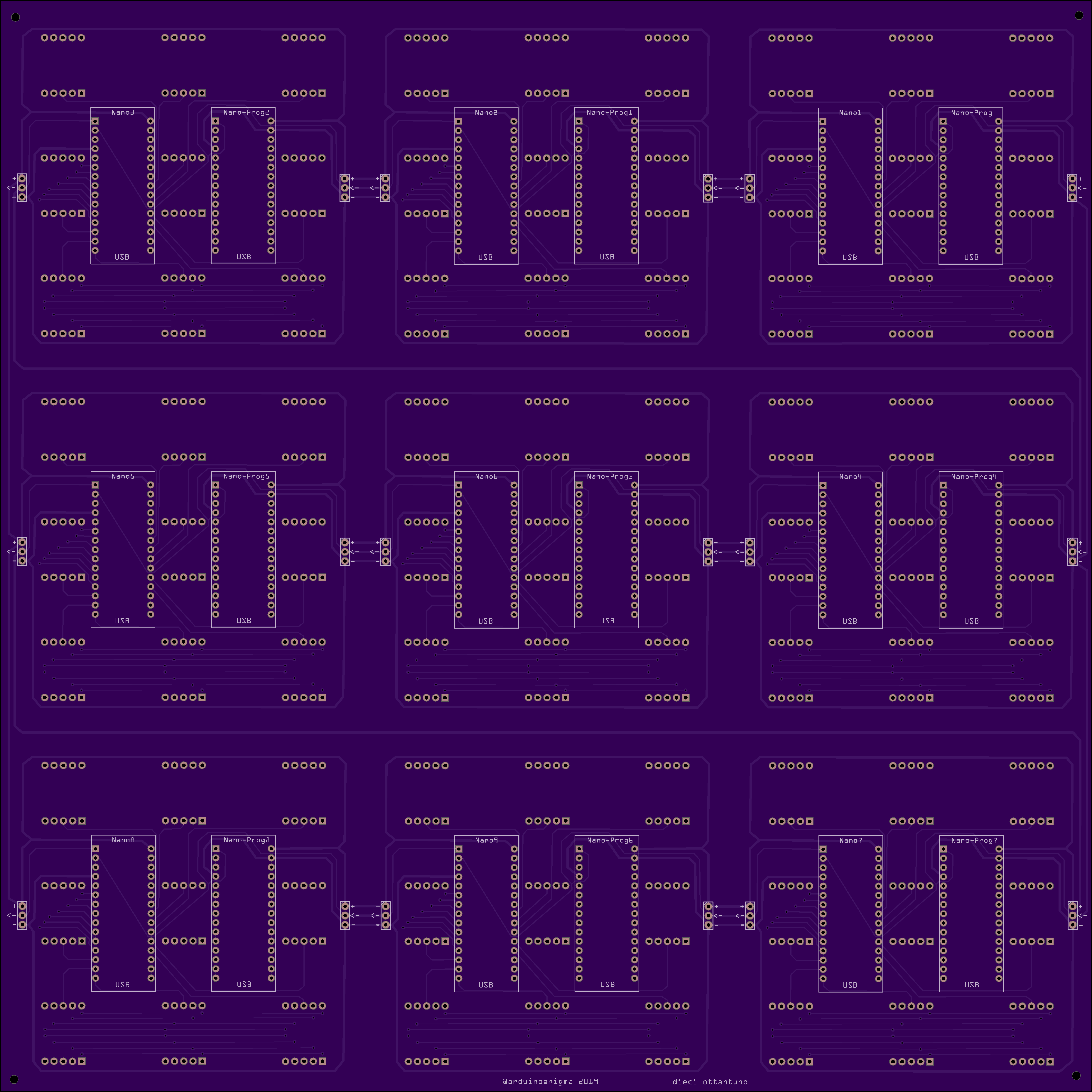
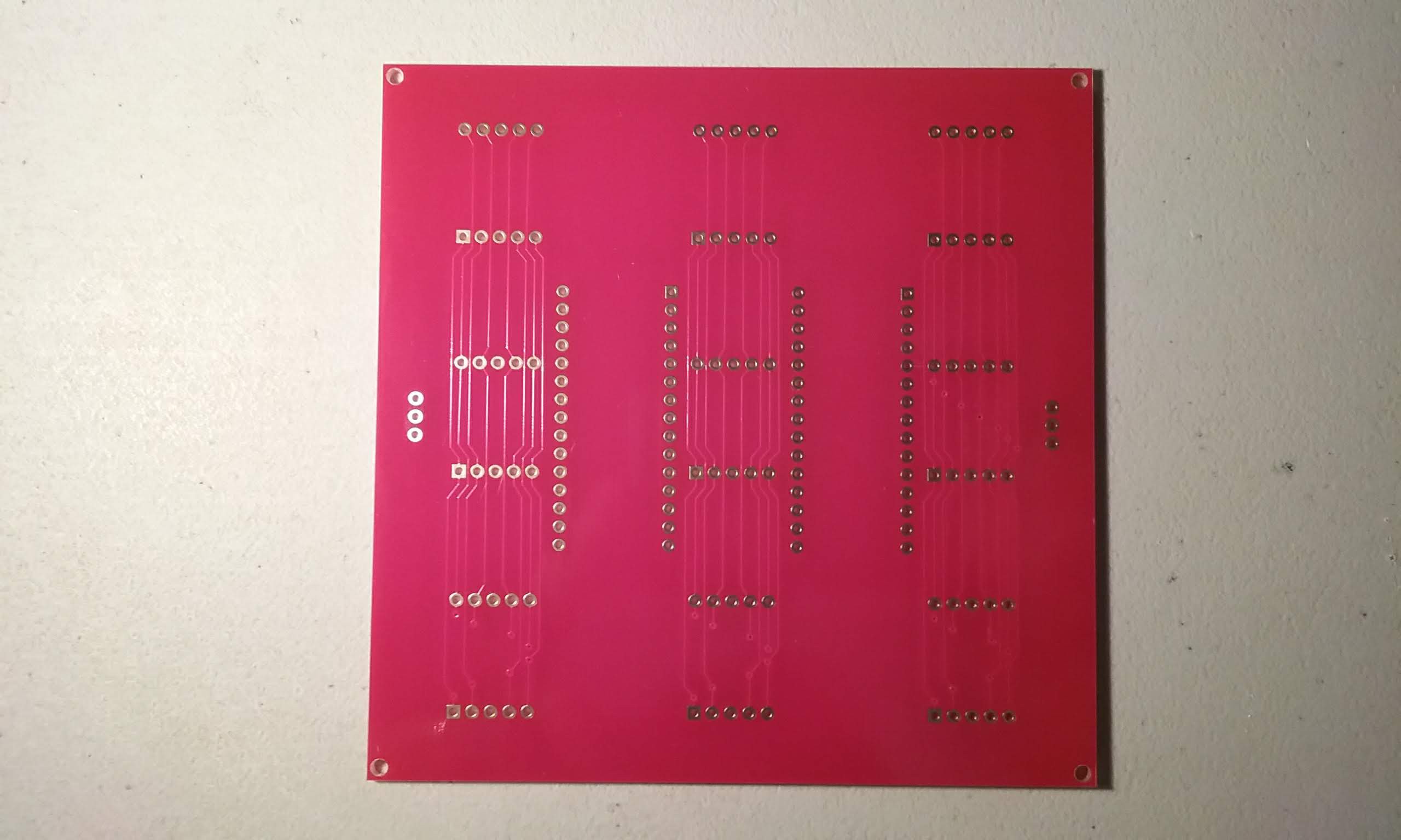
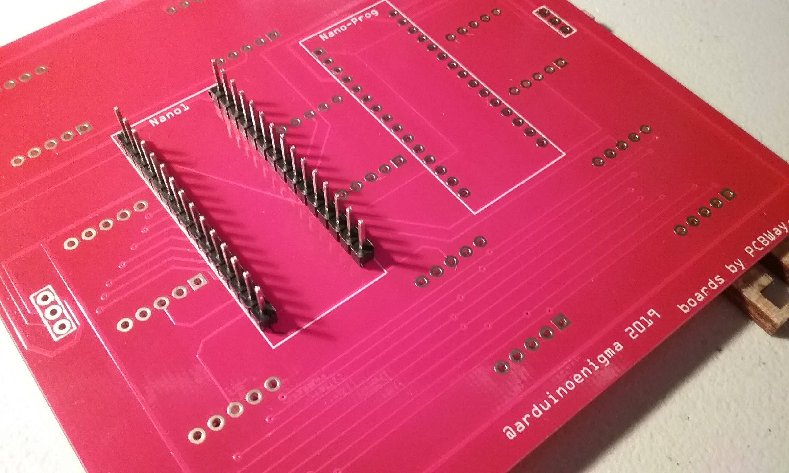
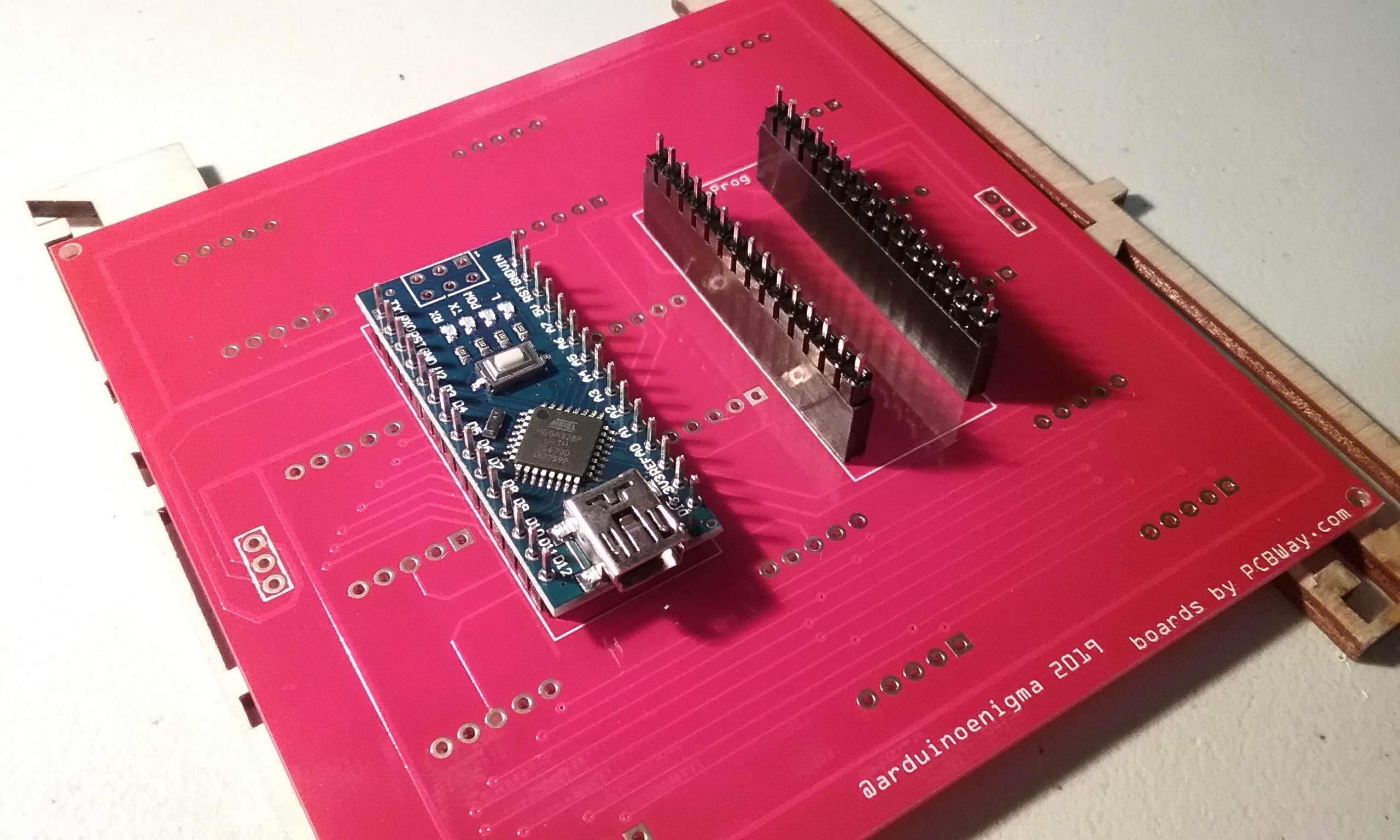
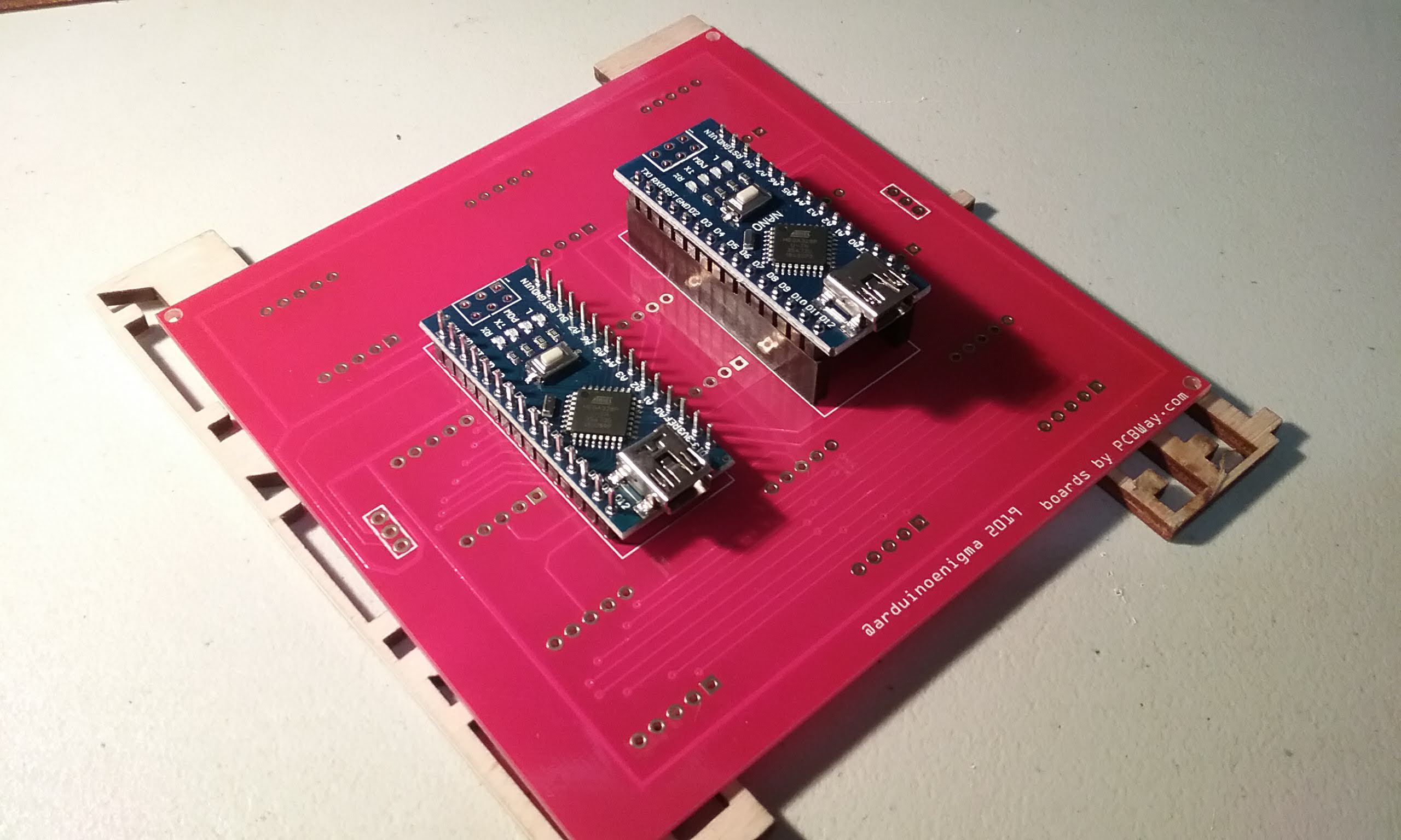
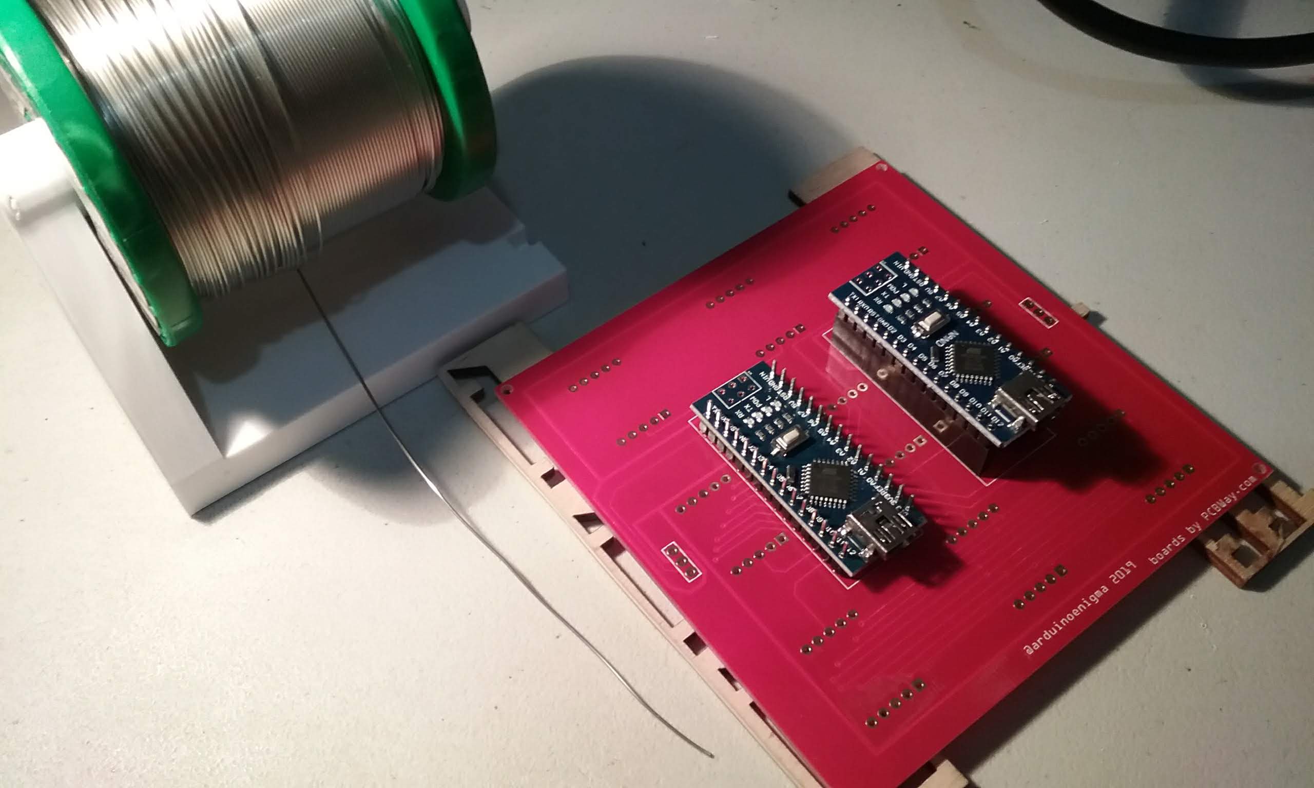
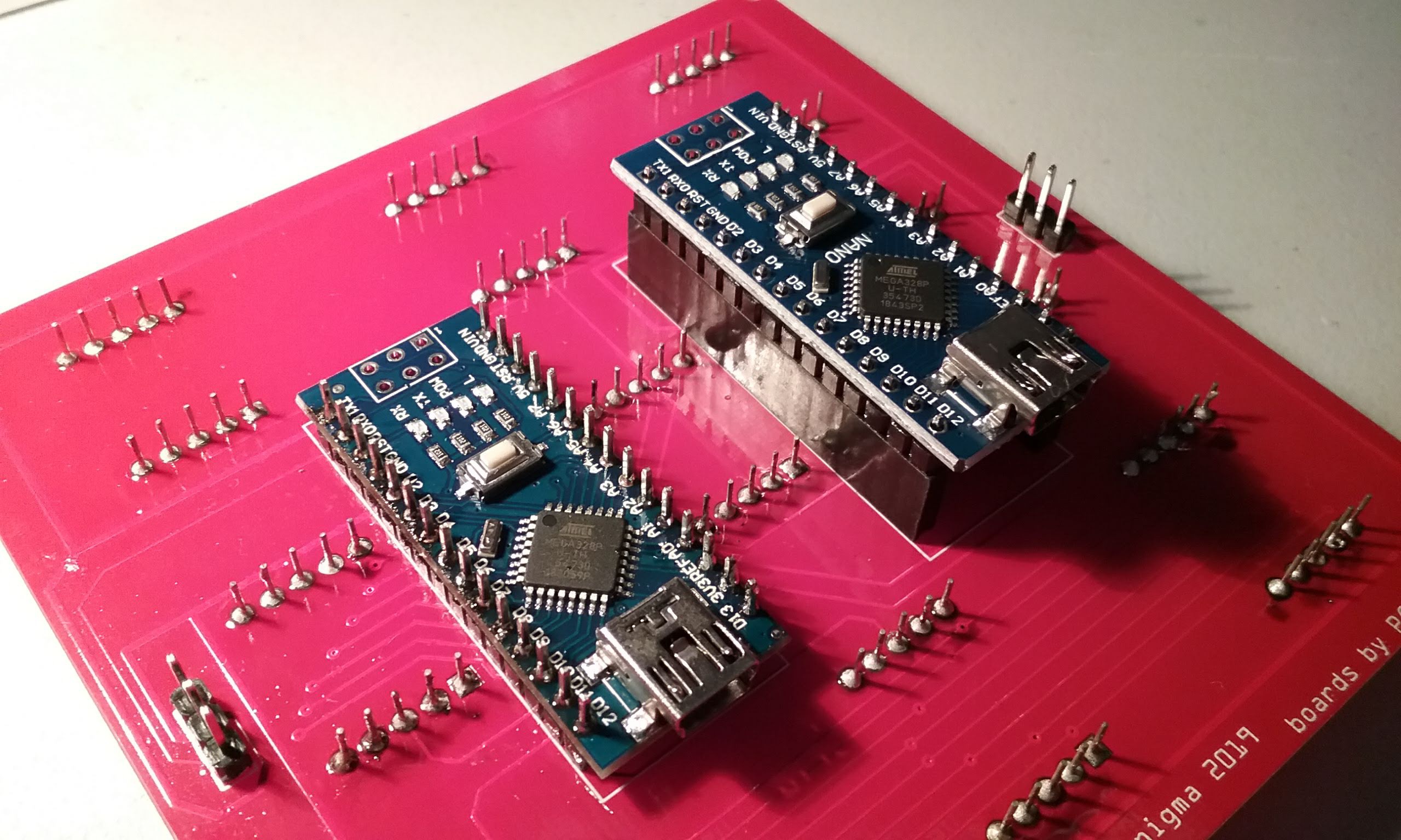
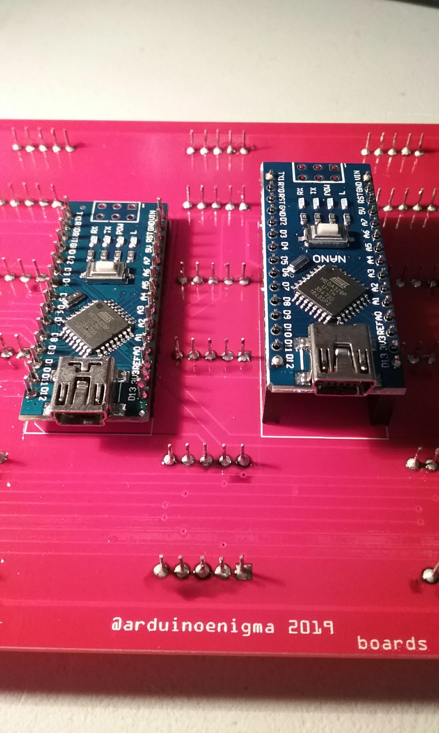
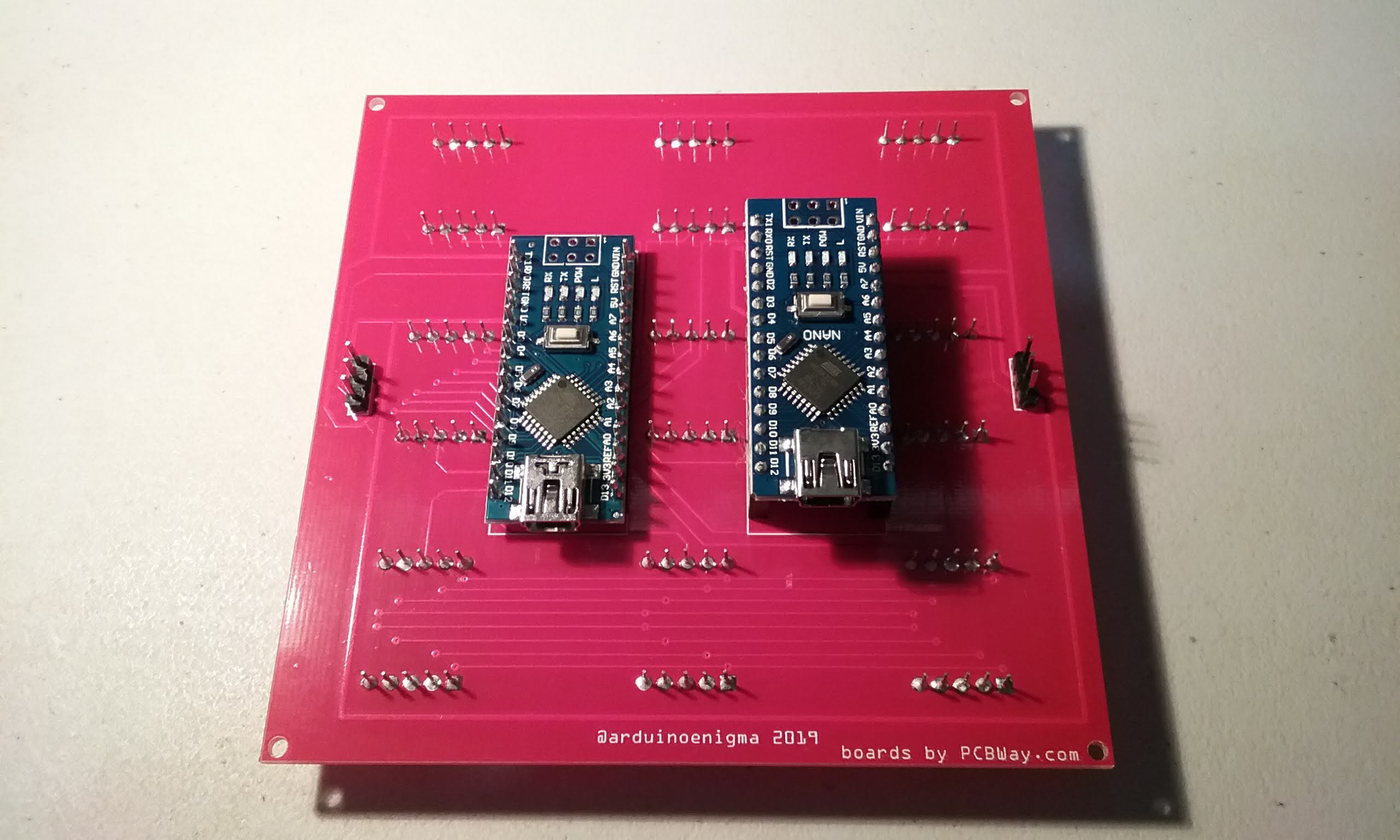
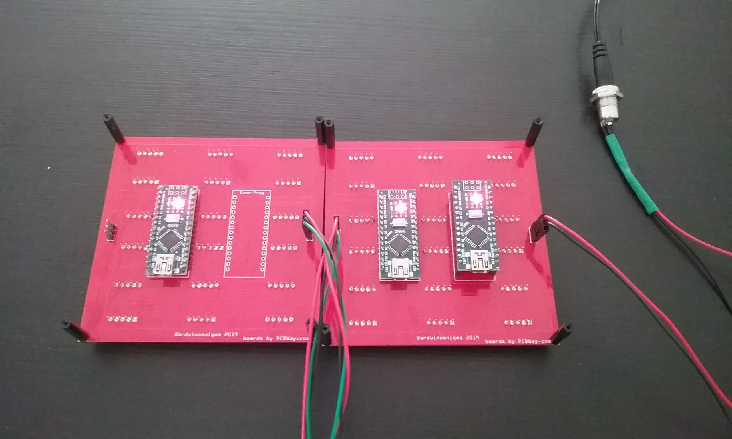
The first tile in the series has two Arduino Nanos soldered, the first one runs the high level animation sketch and sends the commands to light up the LEDs to the display Arduino. The rest of the tiles only have one Arduino
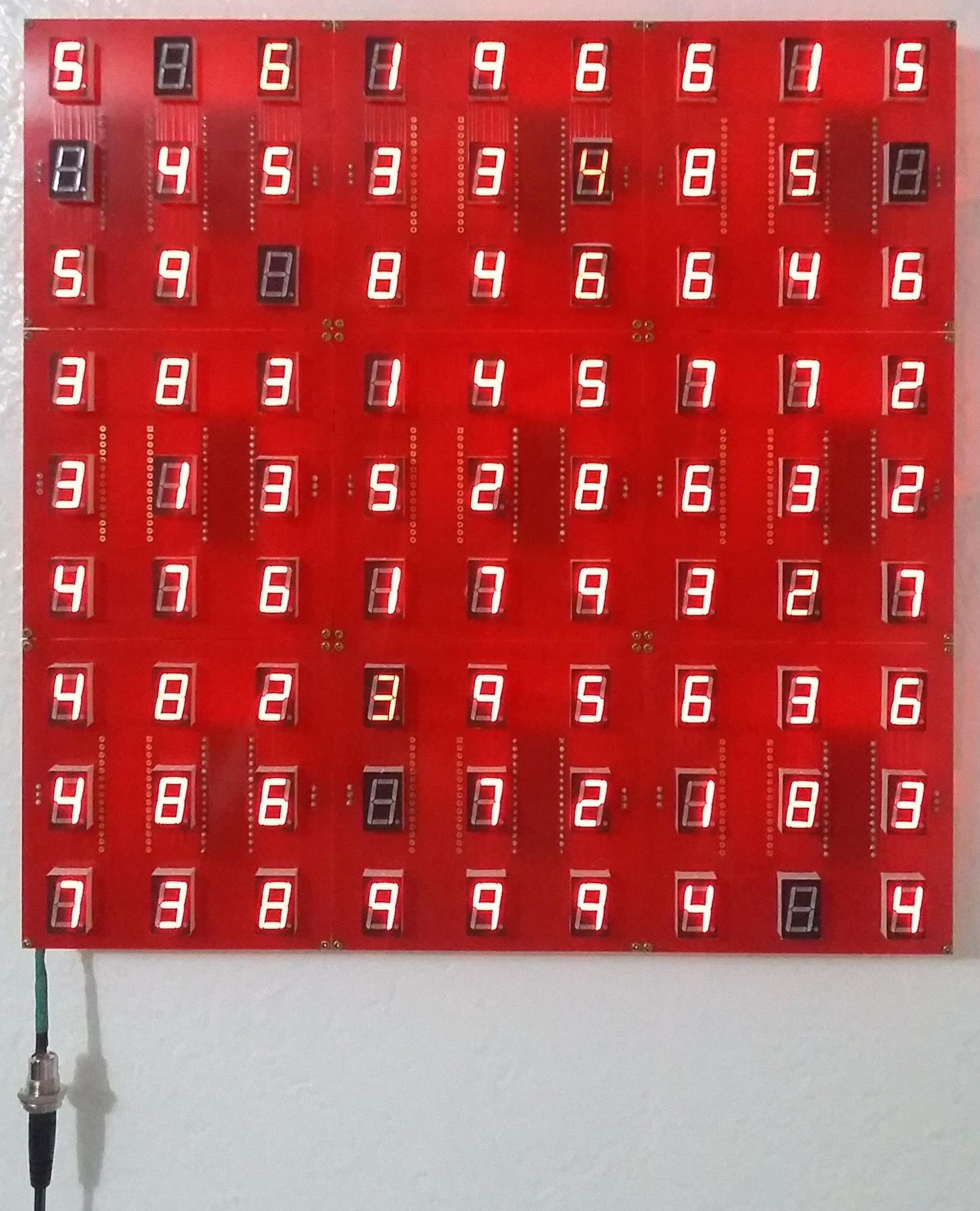
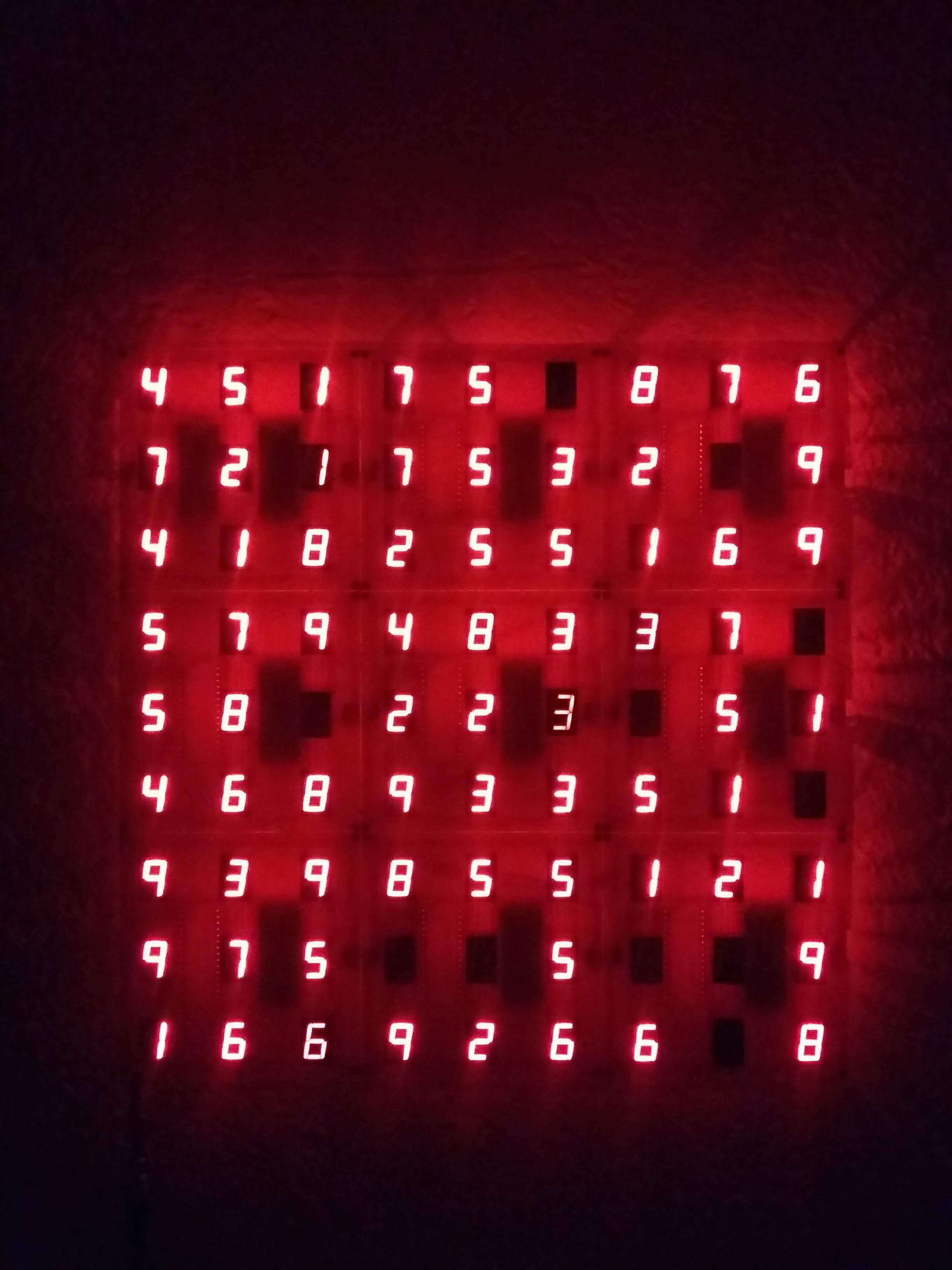
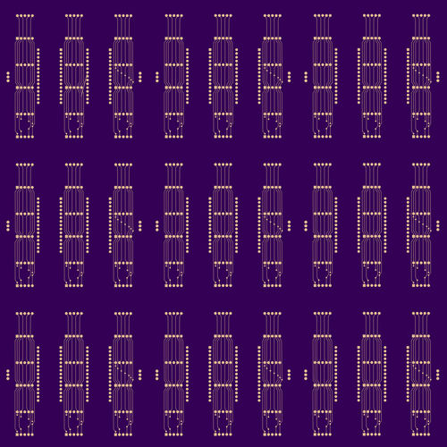
Here it is running a falling digits animation:
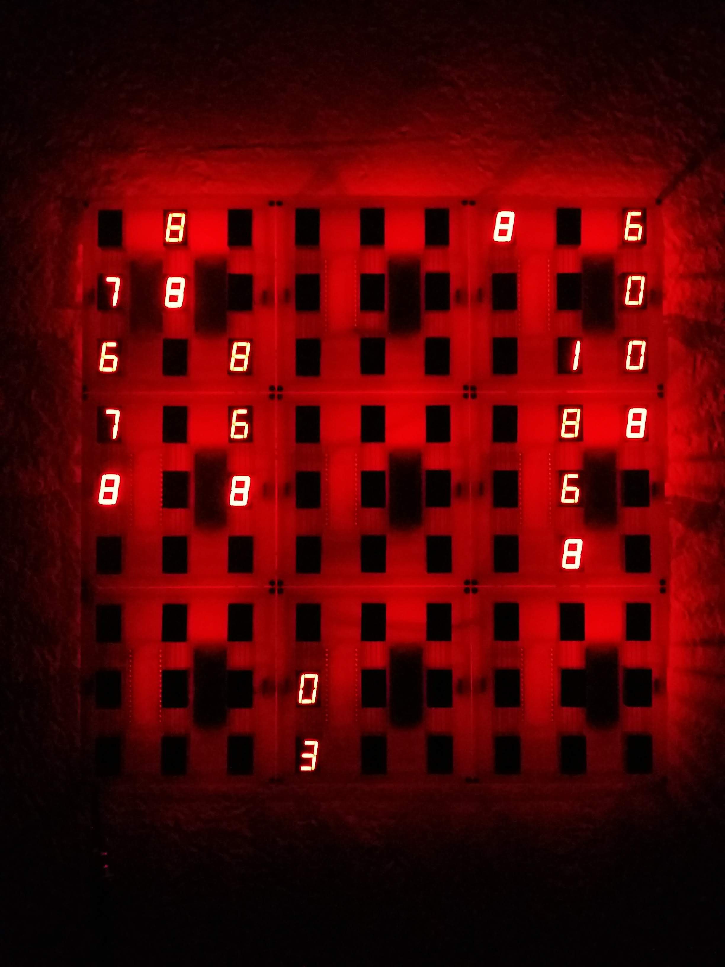
the original animation that inspired this project, numbers increment and fade in, but a blank is shown instead of zero.
A pseudo-random number generator using a Fibonacci Linear Feedback Shift Register:


 maehem
 Craig Hissett