 Arduino Enigma
The following pictures show the assembly process for a one Arduino Nano slave tile. Shown also are the steps that need to be taken once to make a master tile with two Arduino Nanos.
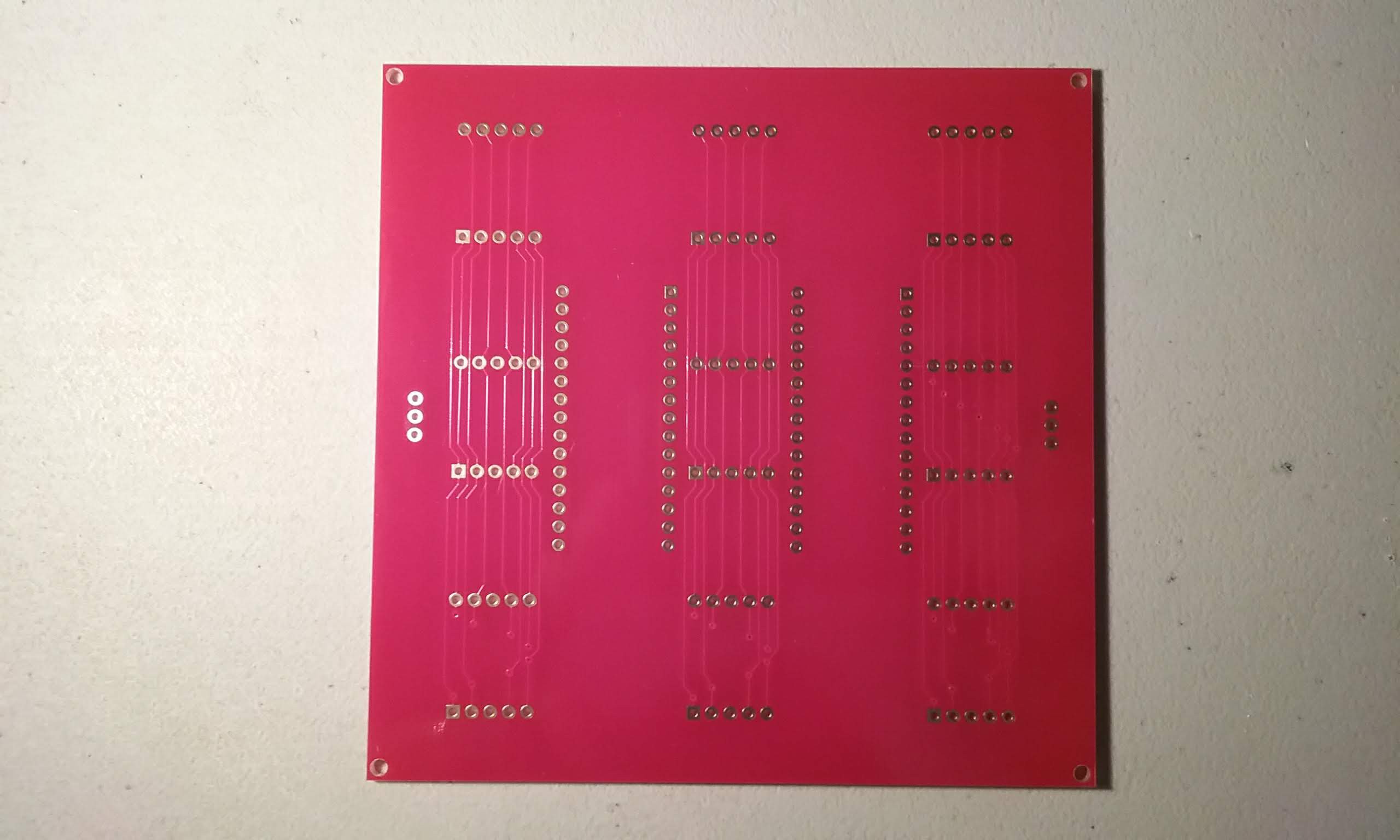
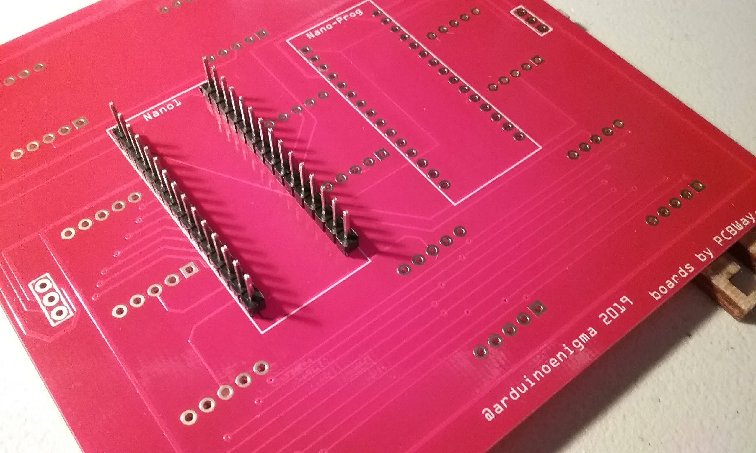
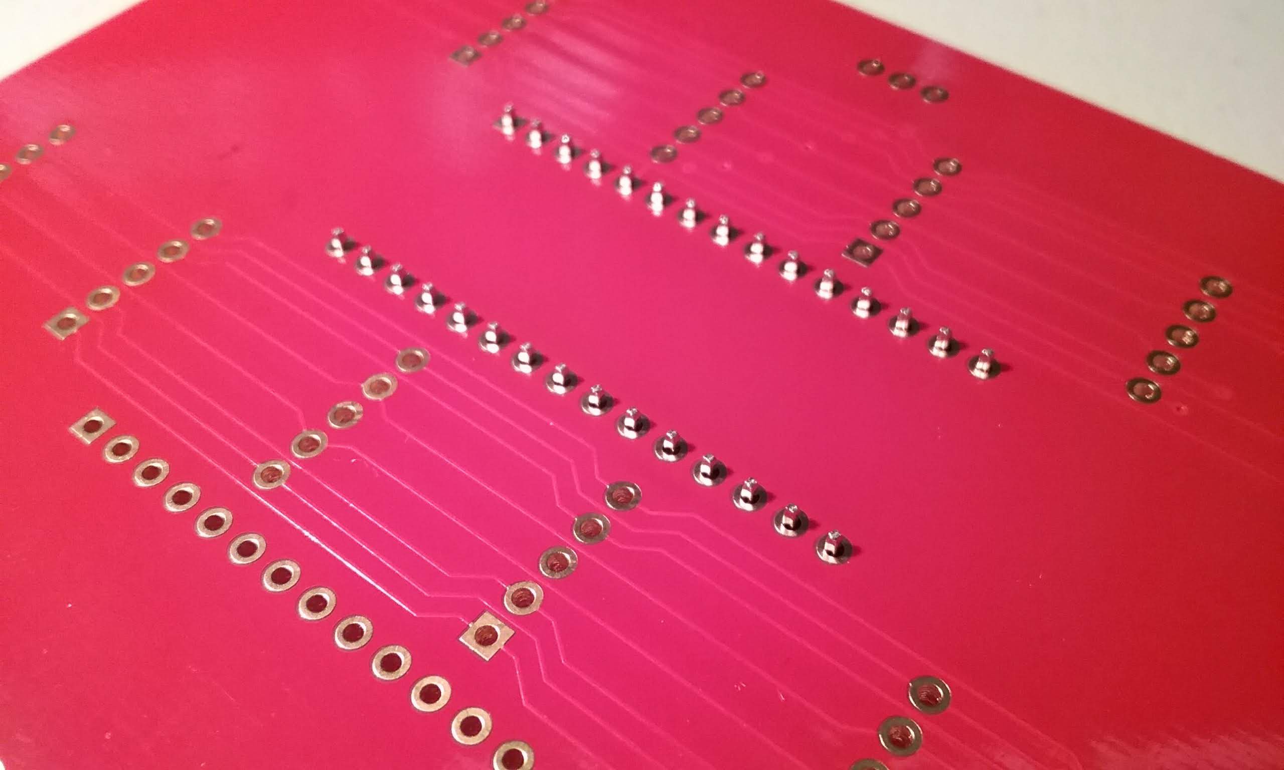
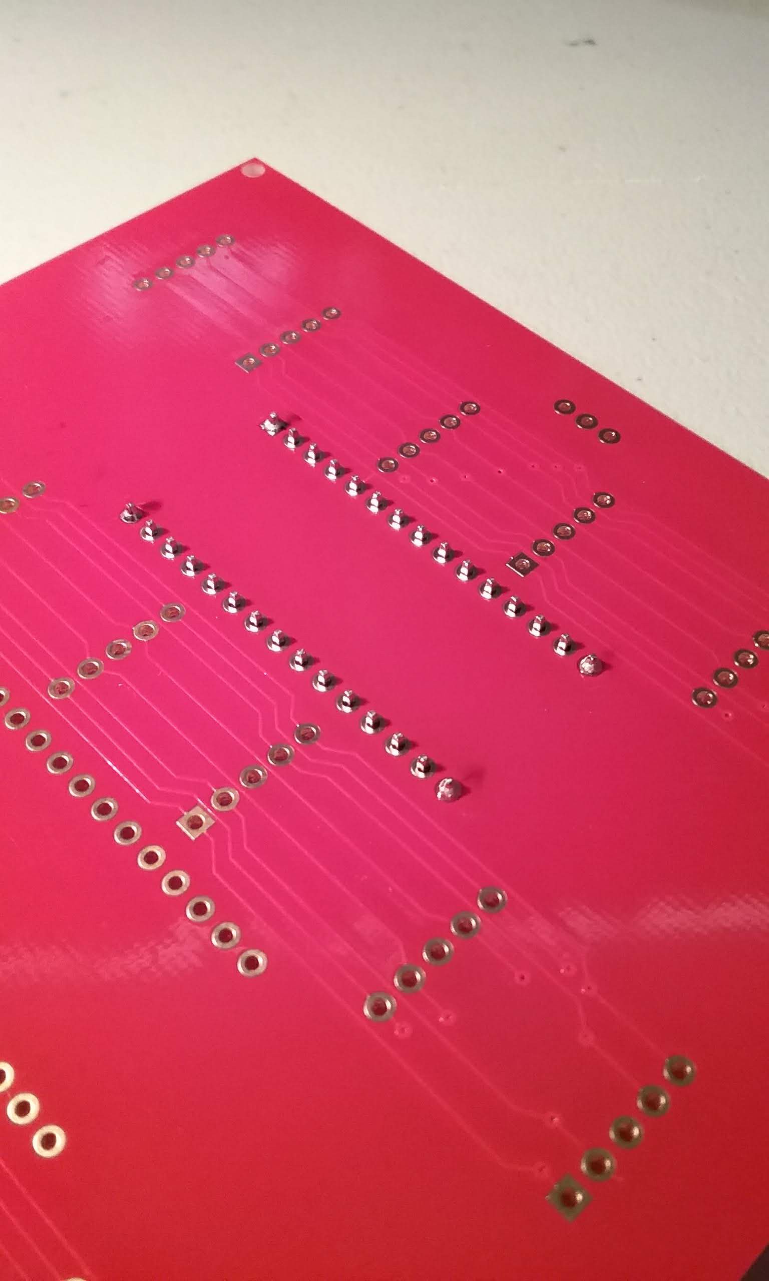
It all starts with ordering this board. Some work went into making sure the front was clean of marks, the only clue that this is oriented the right way is that the vias on the lower part. Those vias will be hidden under the displays when this is assembled.
In order to keep the front of the board clean, it is important to put on the order a note: "do not add order number to board" PCBWay has been good about doing this.
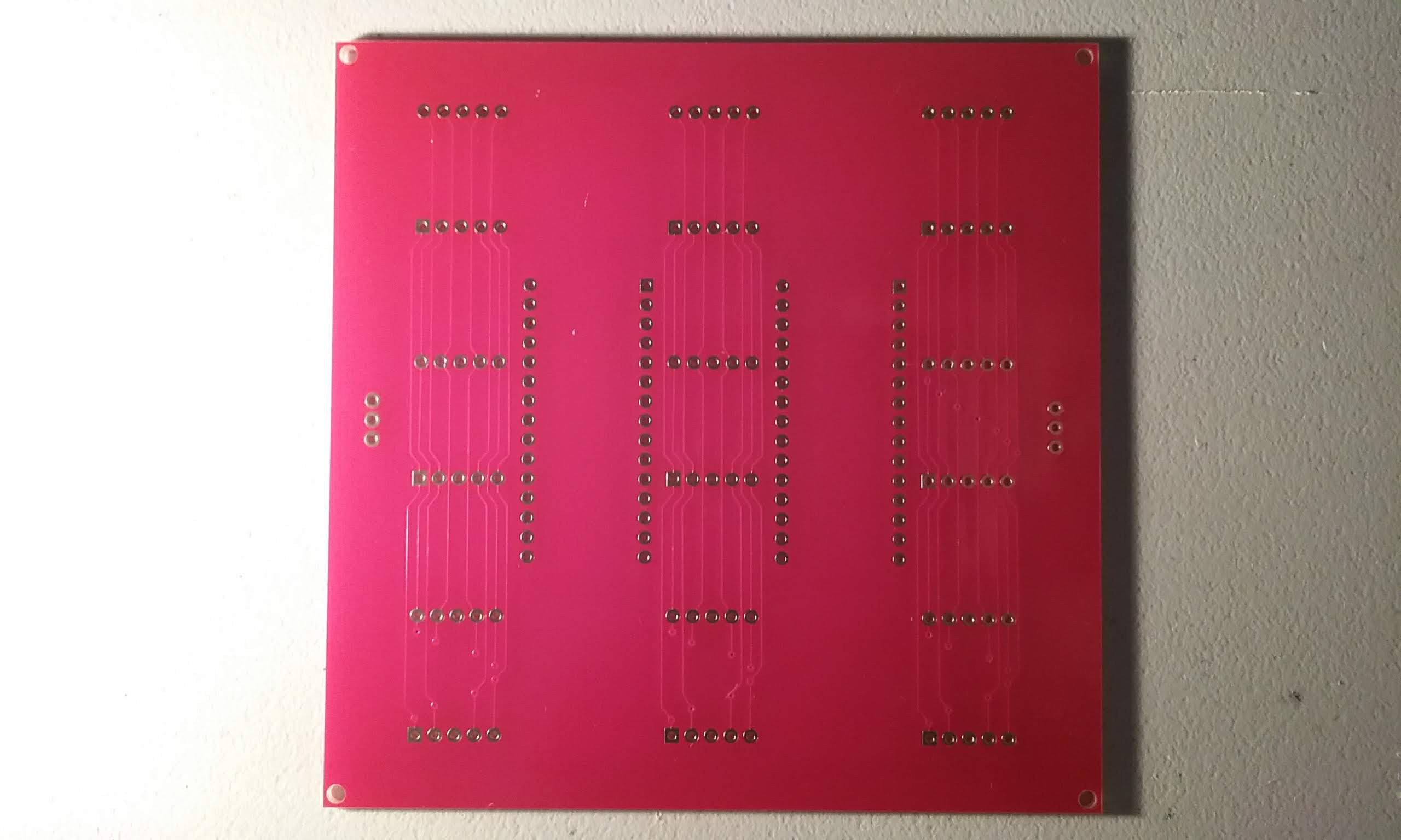
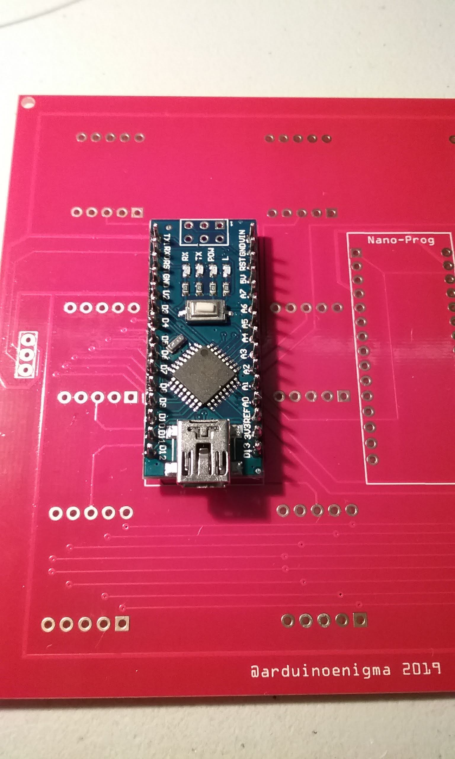
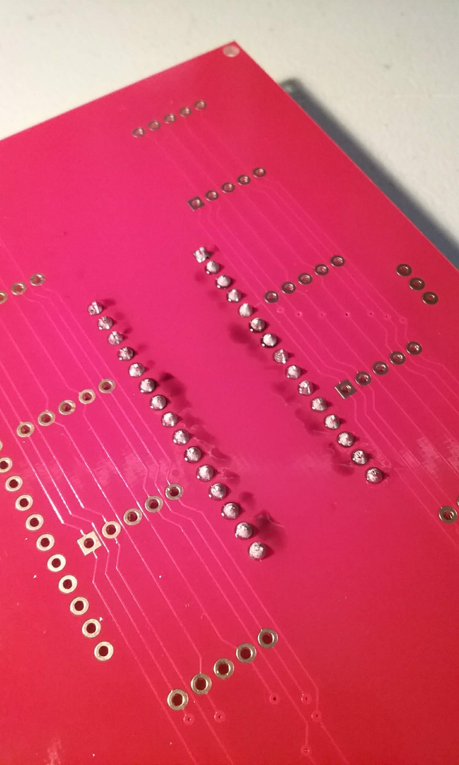
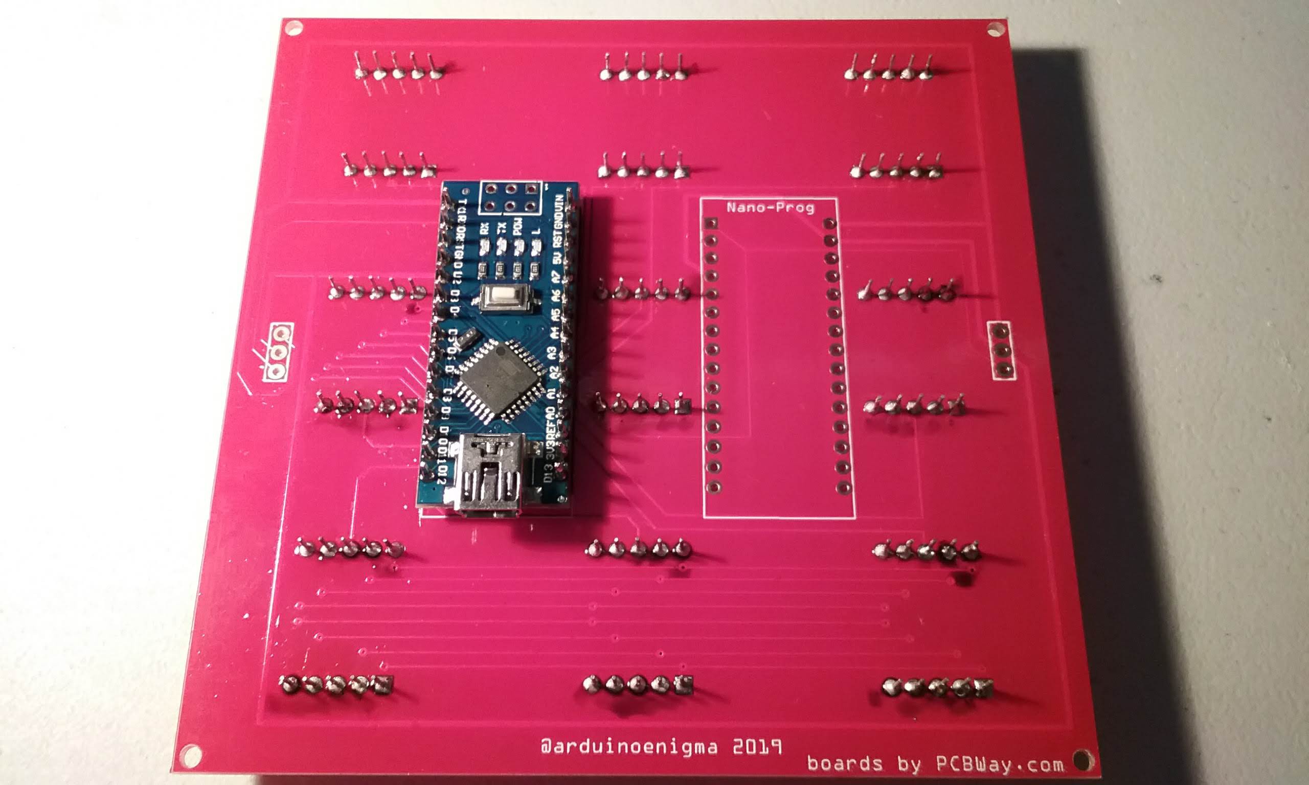
Here is a shot of the back. It has a few silkscreen markings, but those will almost disappear once assembled.
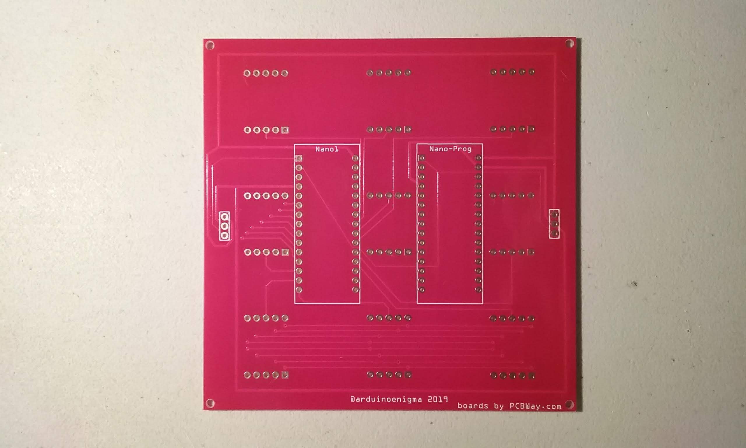
Trying to show the traces in the front. The red soldermask is really, really shiny and hides the tracks...
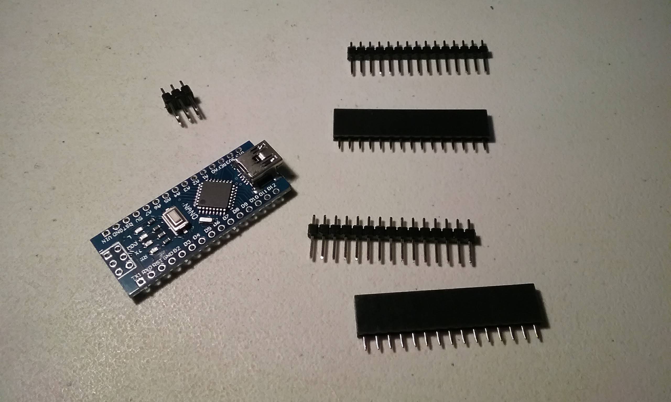
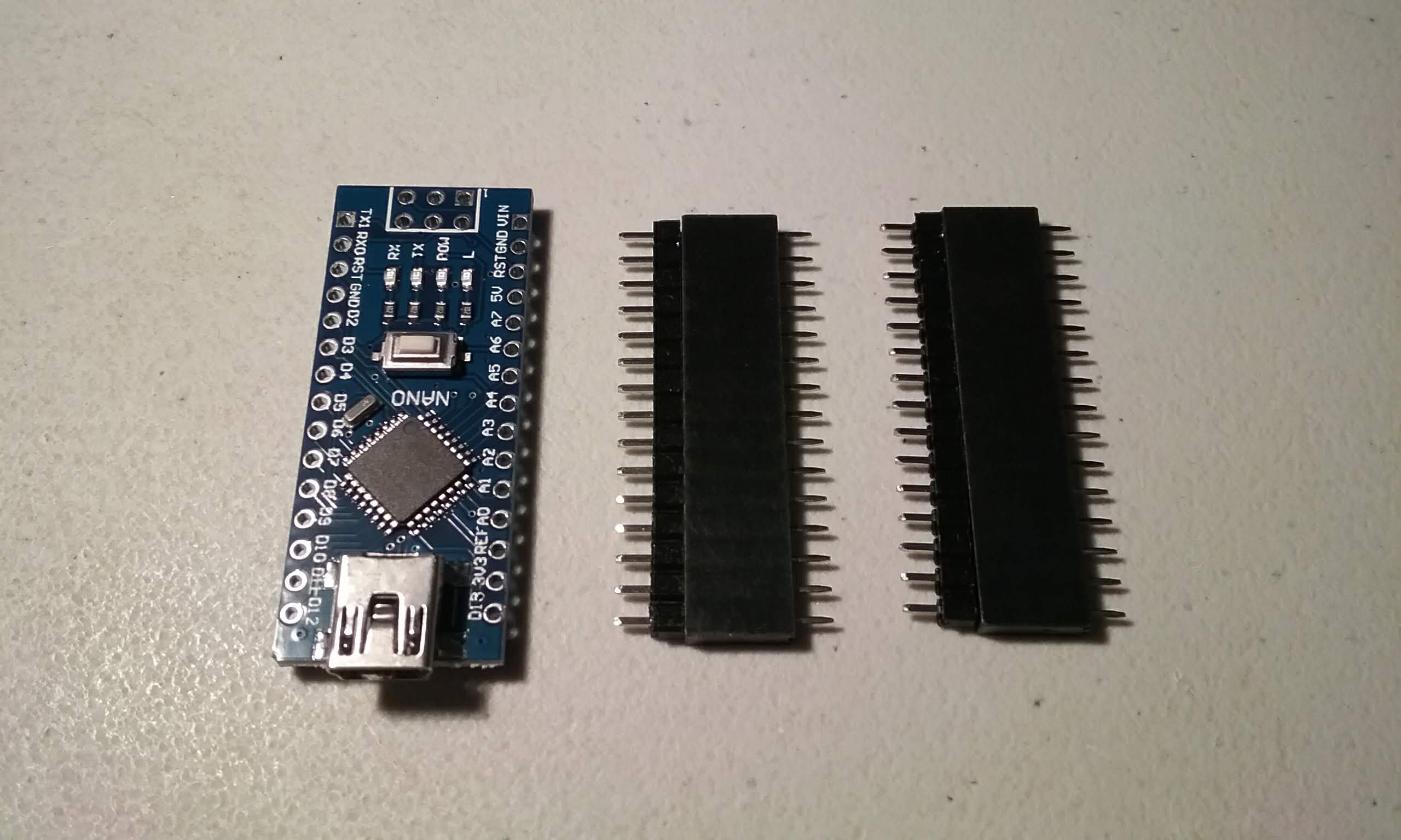
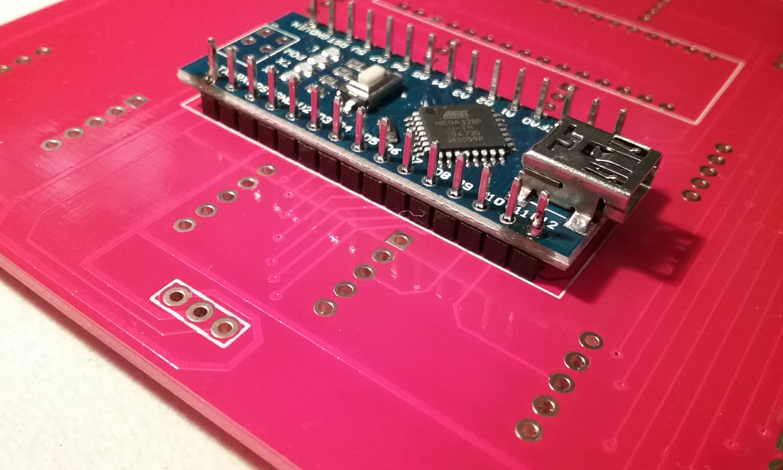
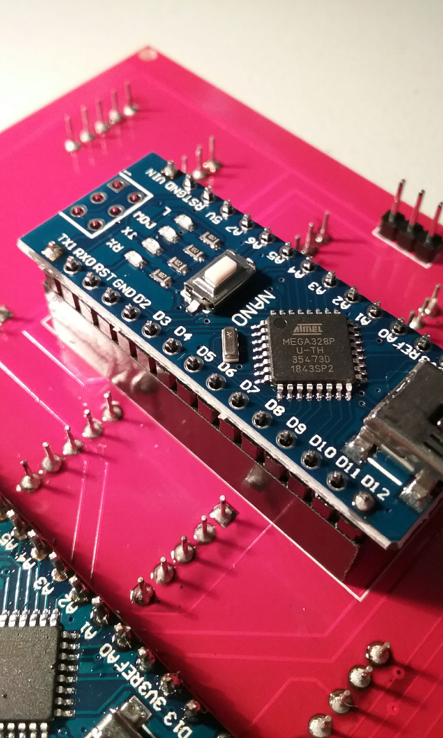
Unpack an Arduino Nano, two if building a master tile. The 6 pin connector can be ignored.
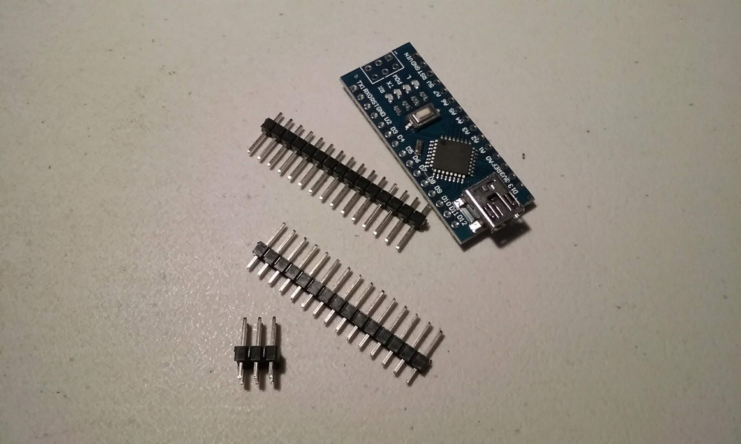
Flip the board and insert the headers short pins first. We don't want pins sticking out of the front.
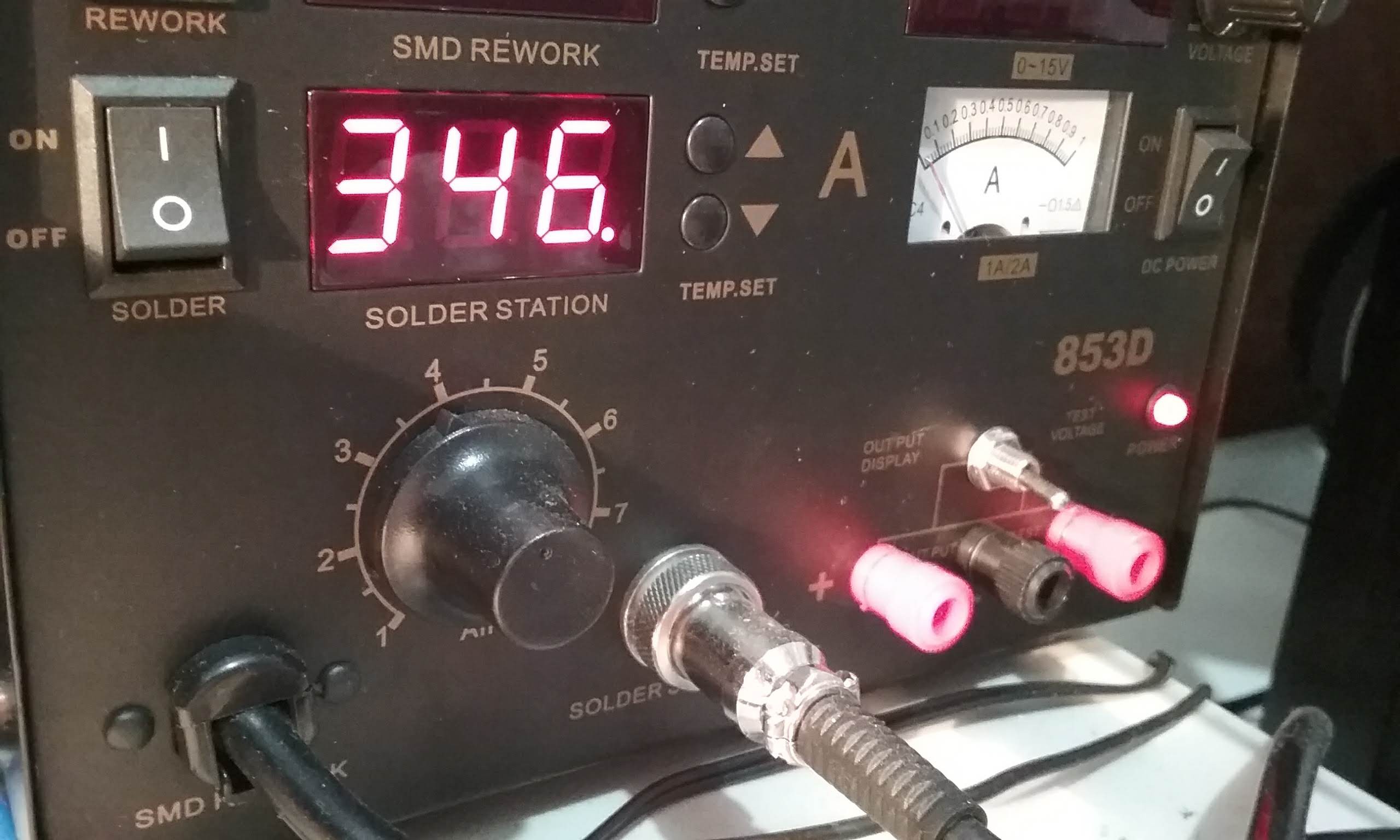
And now is a good time to start heating the soldering iron.
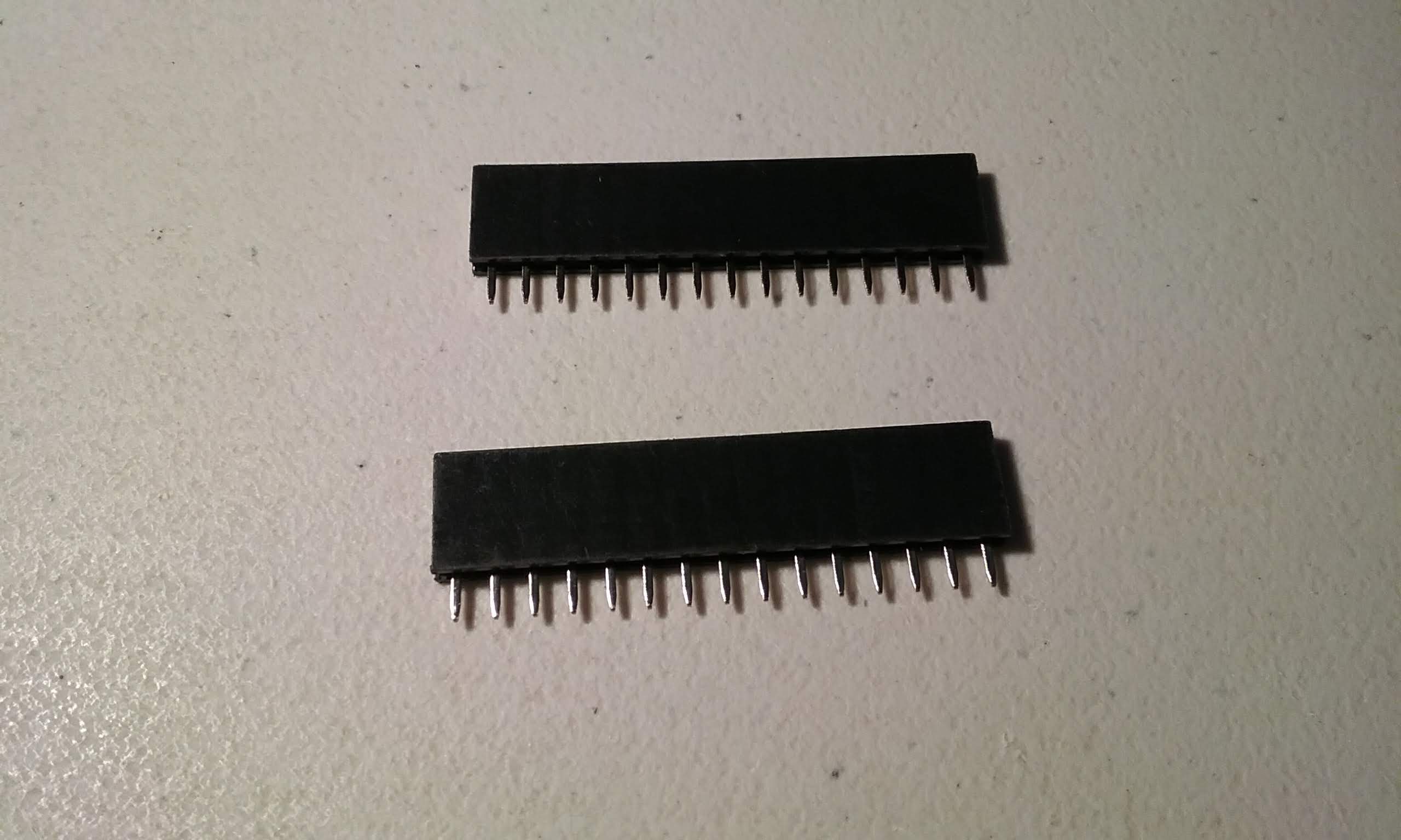
If building a master tile, prepare two 15 pin female headers.
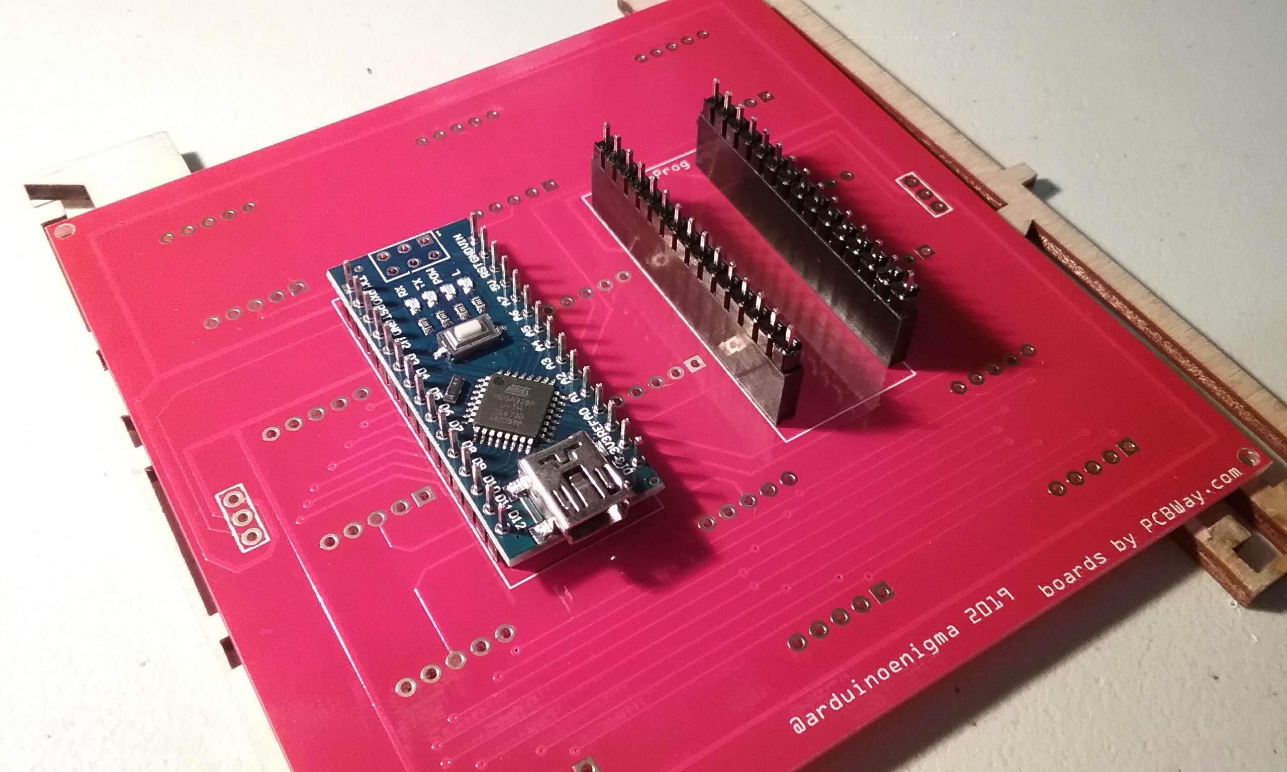
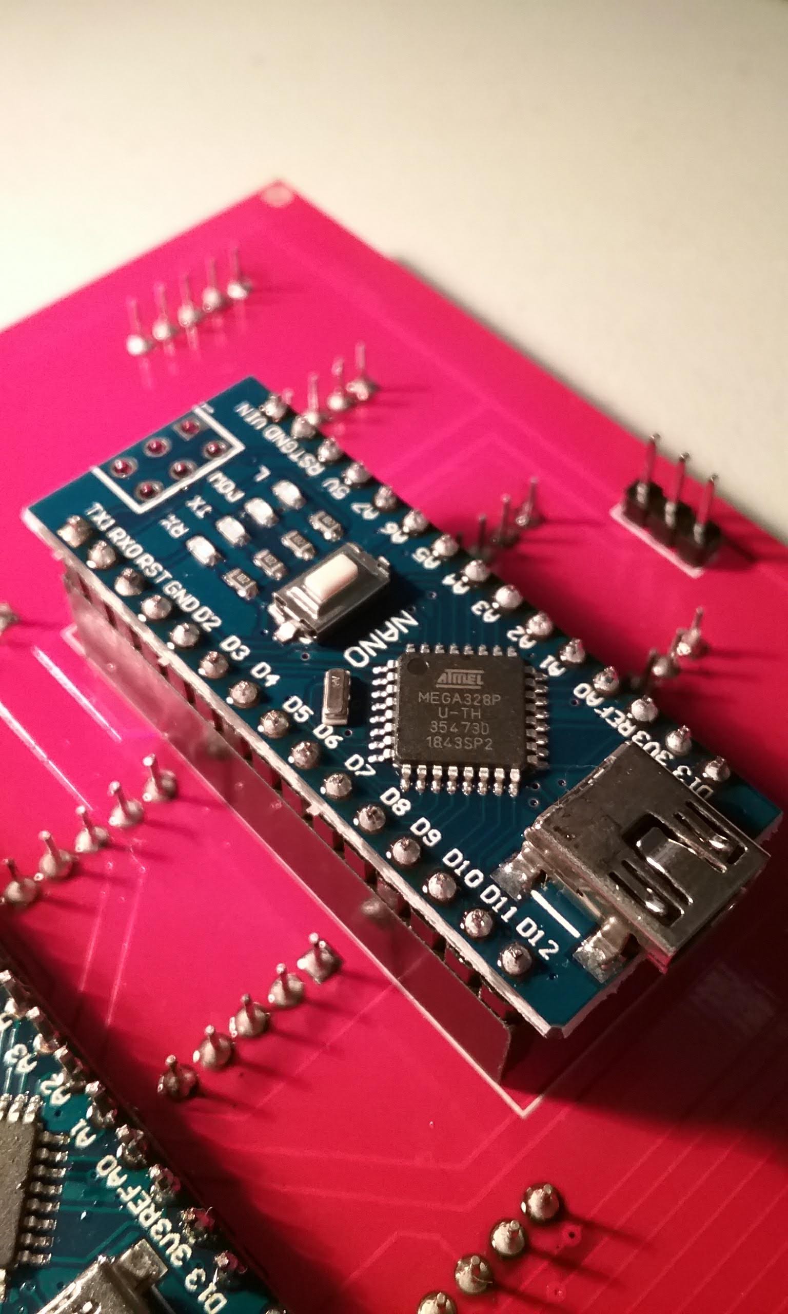
This Arduino Nano will become the master.
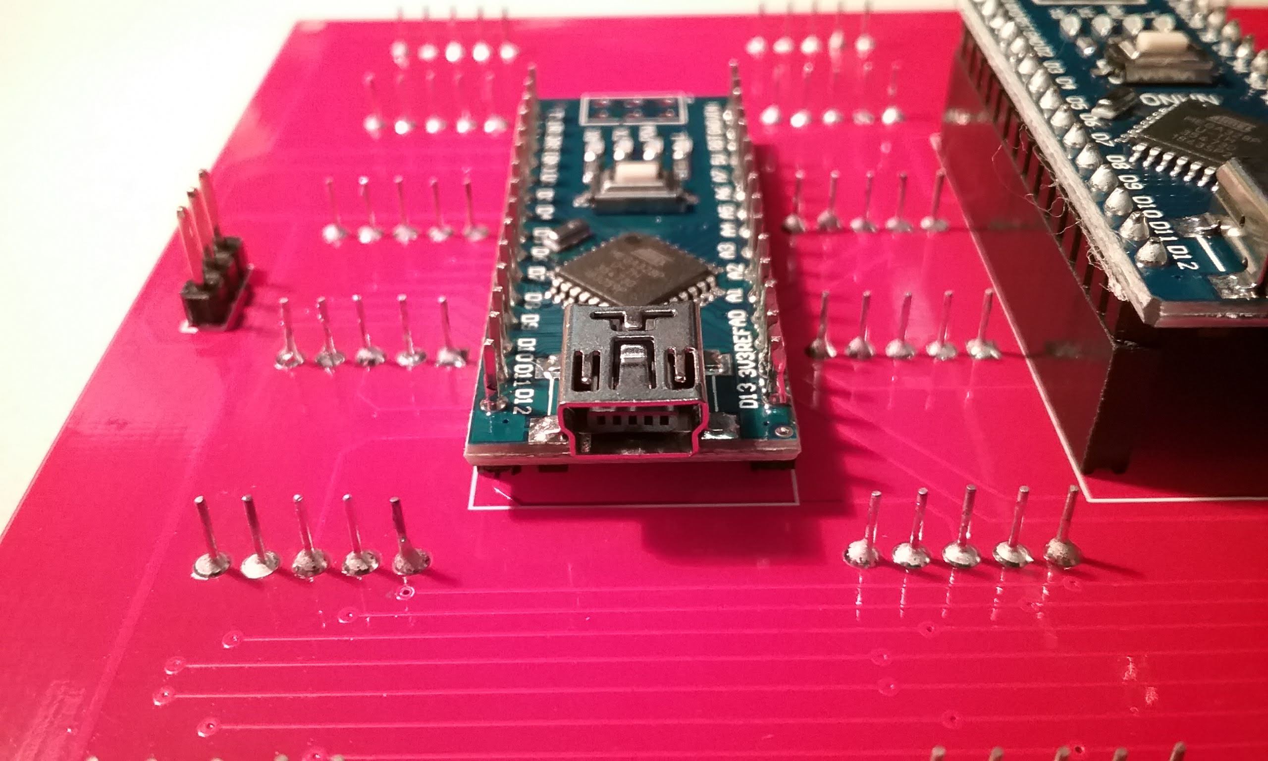
Insert the Arduino headers long end first into the female headers.
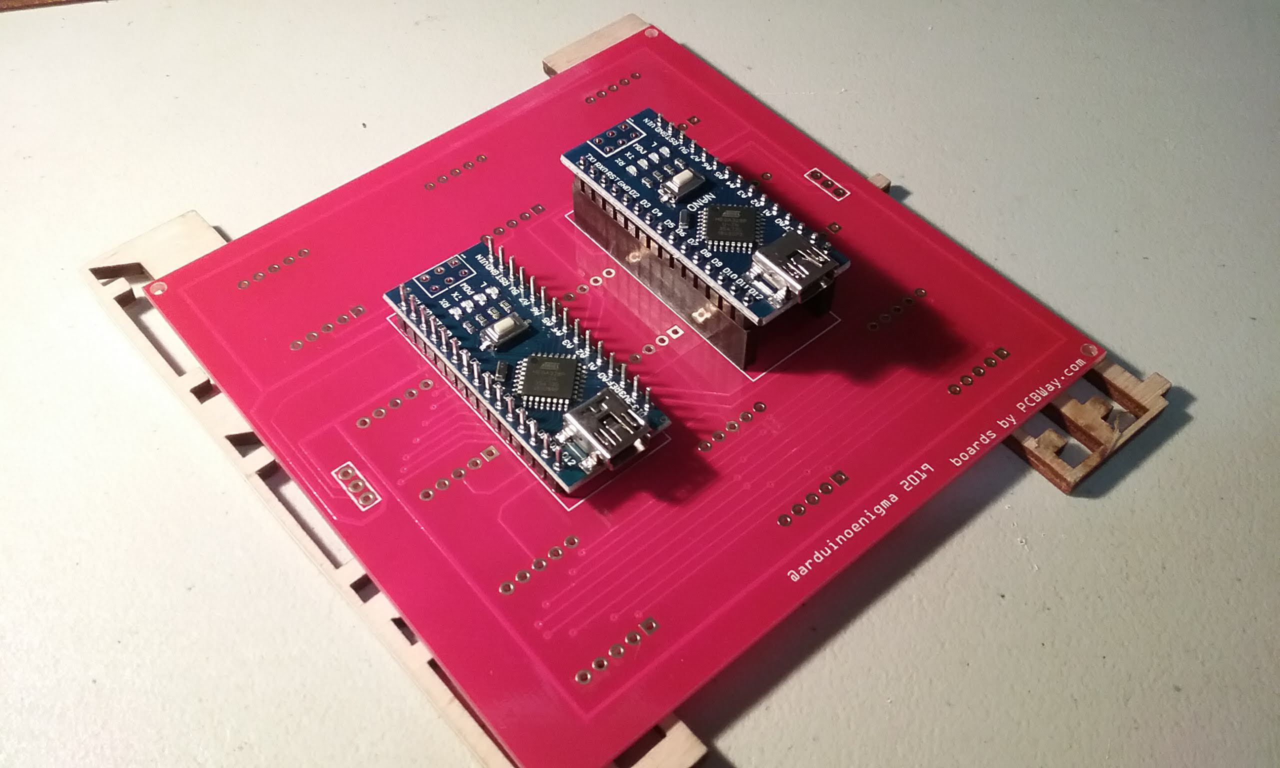
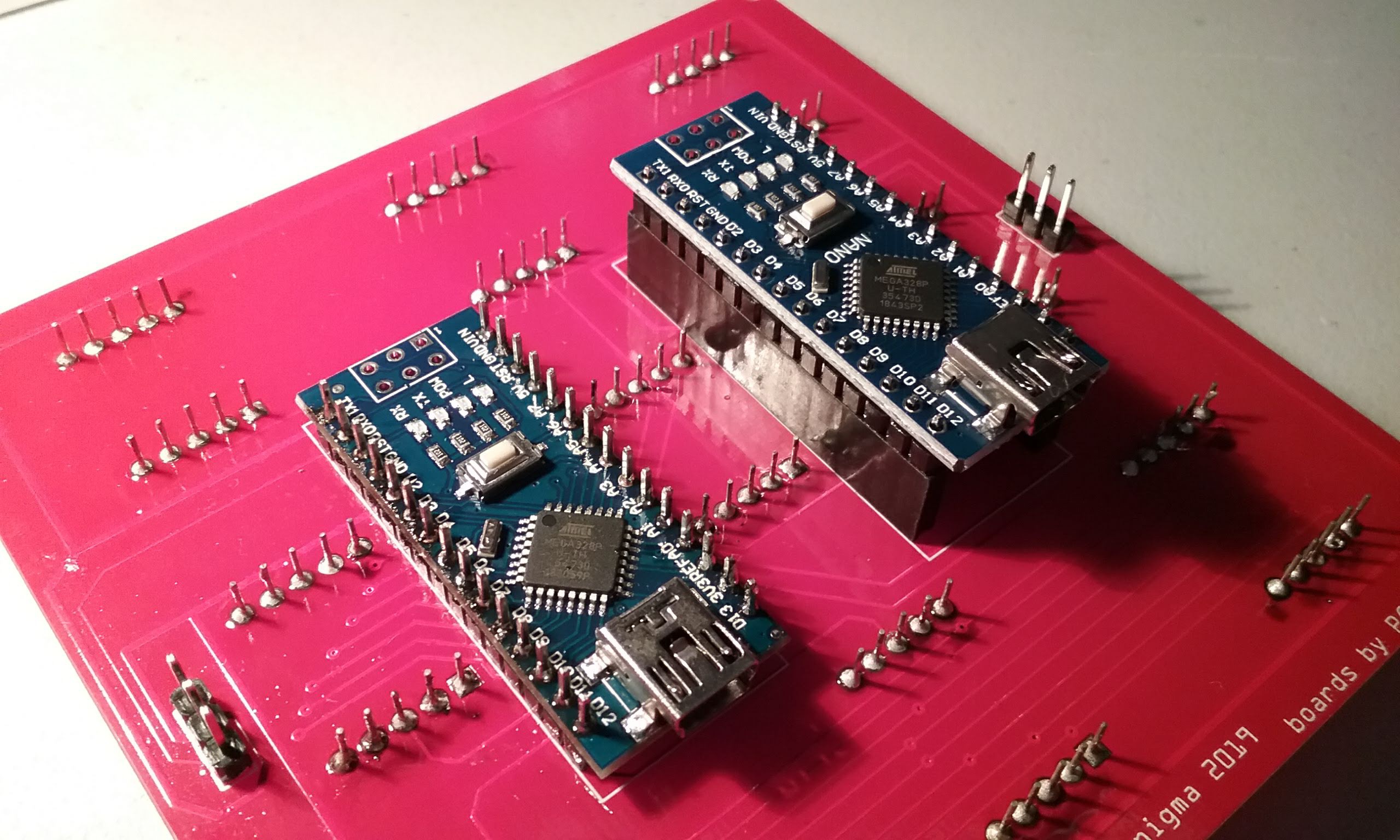
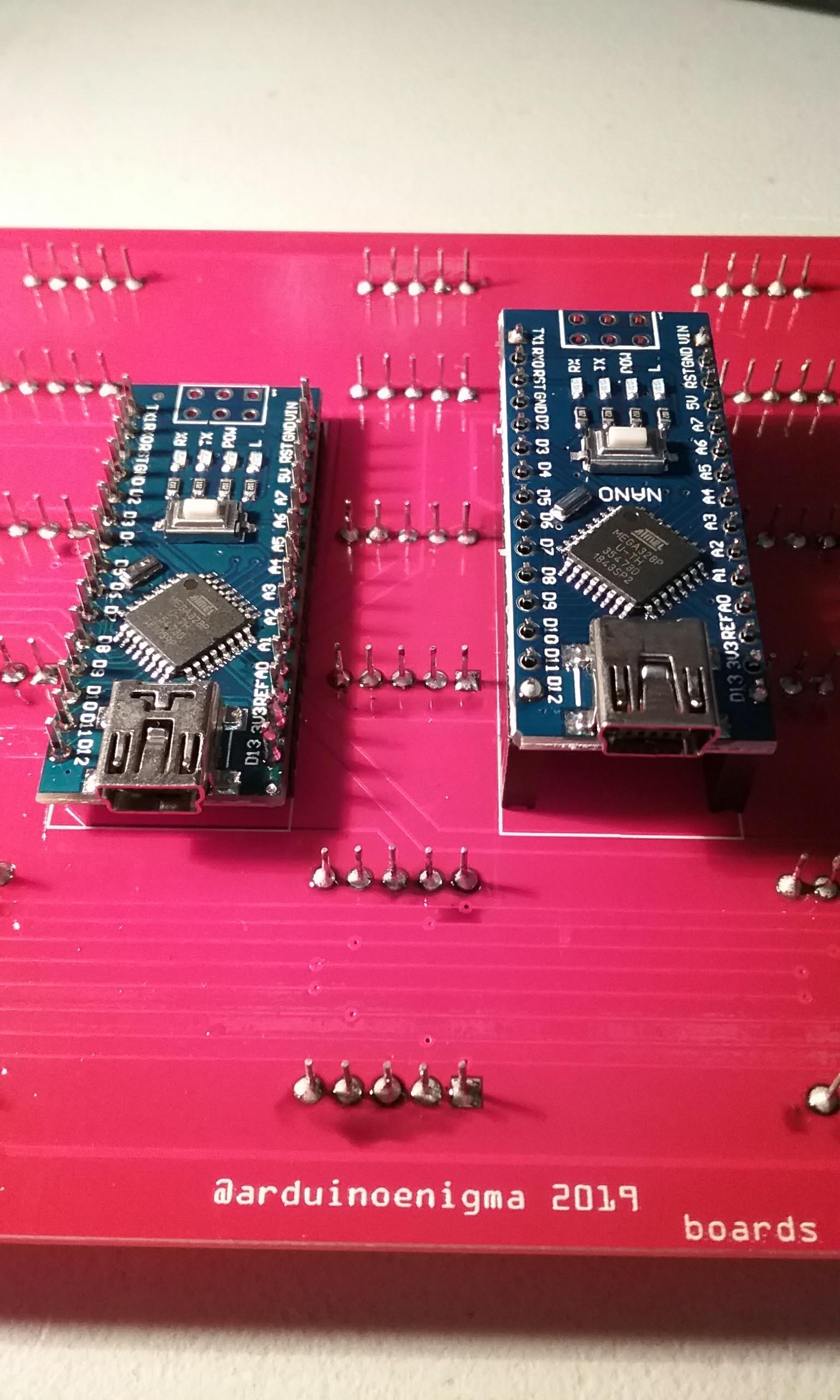
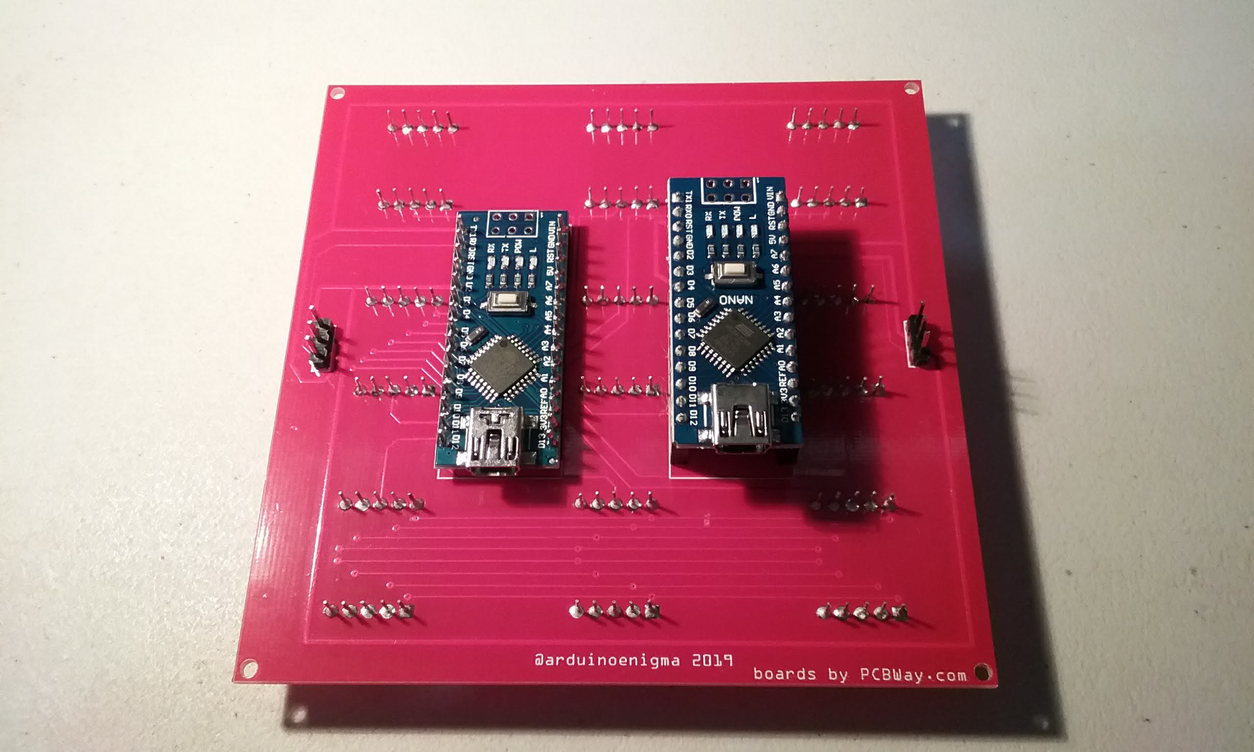
And here we are mocking how the Arduinos go on the tile. The display Arduino has the short side of the pins inserted on the board and the master Arduino goes into headers.
Mocking how the Arduinos will look.
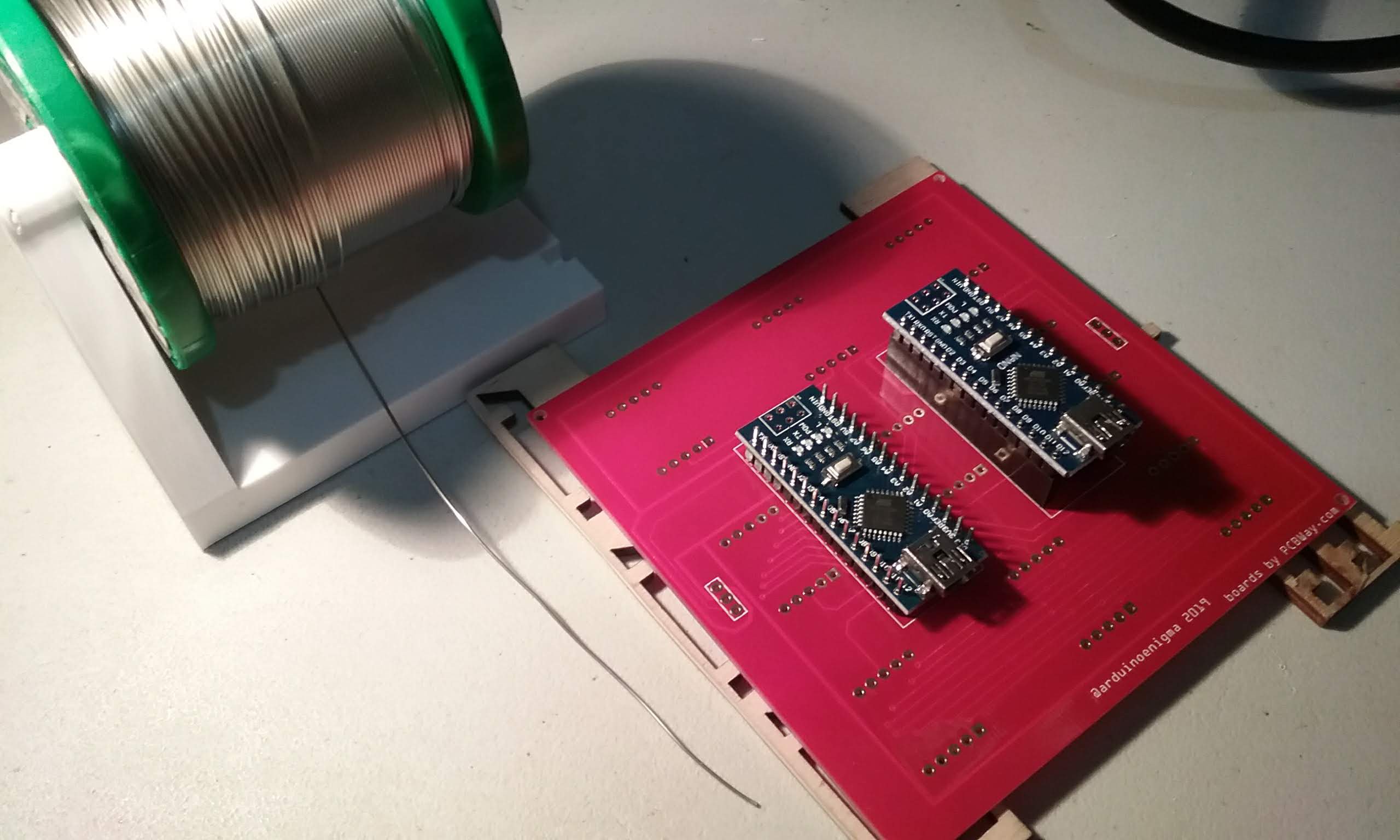
Get the solder ready. I like this Alpha Pure Core Water Soluble Flux Solder, makes the boards easier to clean at the end of assembly.
Start by soldering the four corners of the headers, make sure everything is fully inserted.
Next, continue soldering the rest of the pins.
Flip the board.
And solder the four corners.
Continue by soldering the rest of the pins.
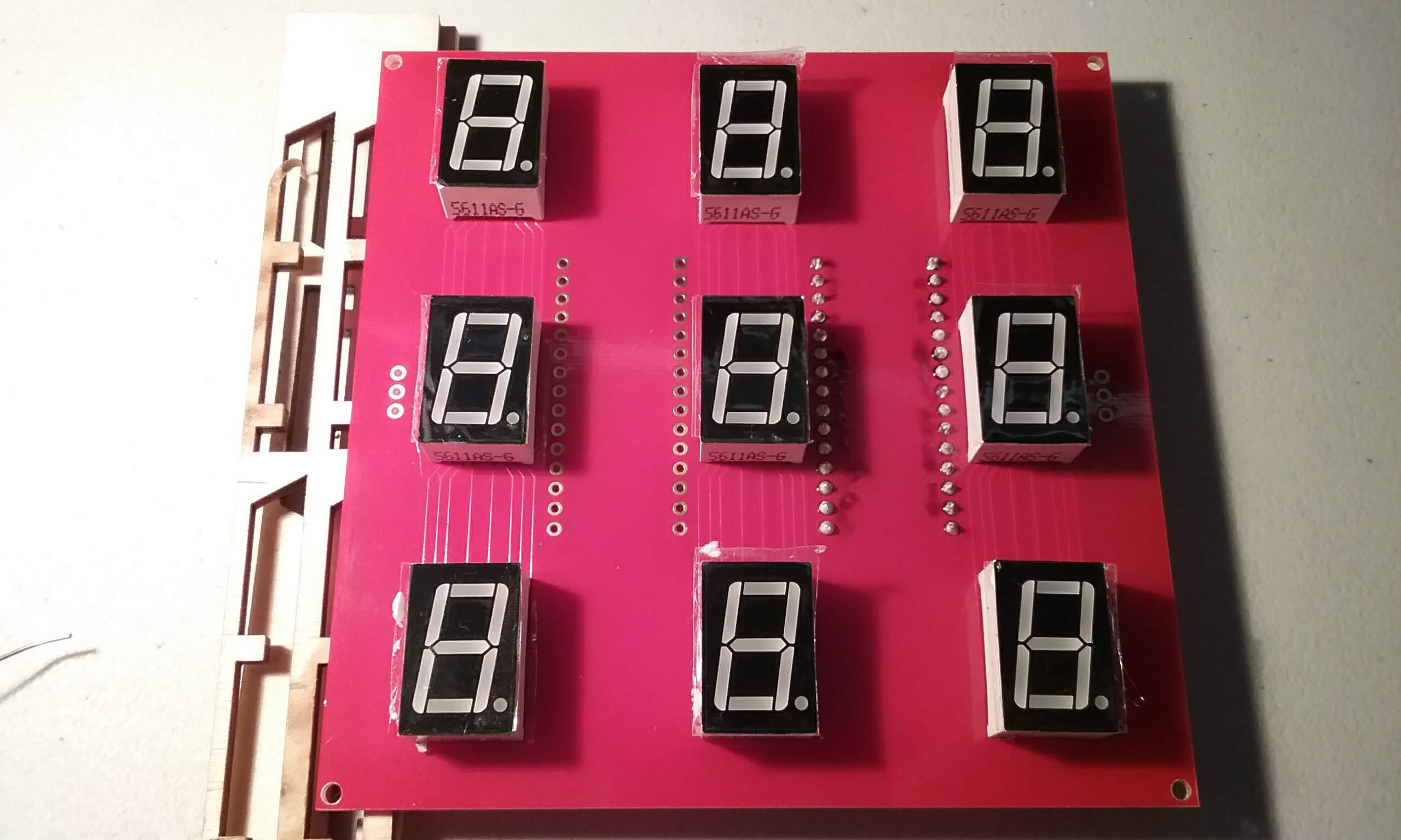
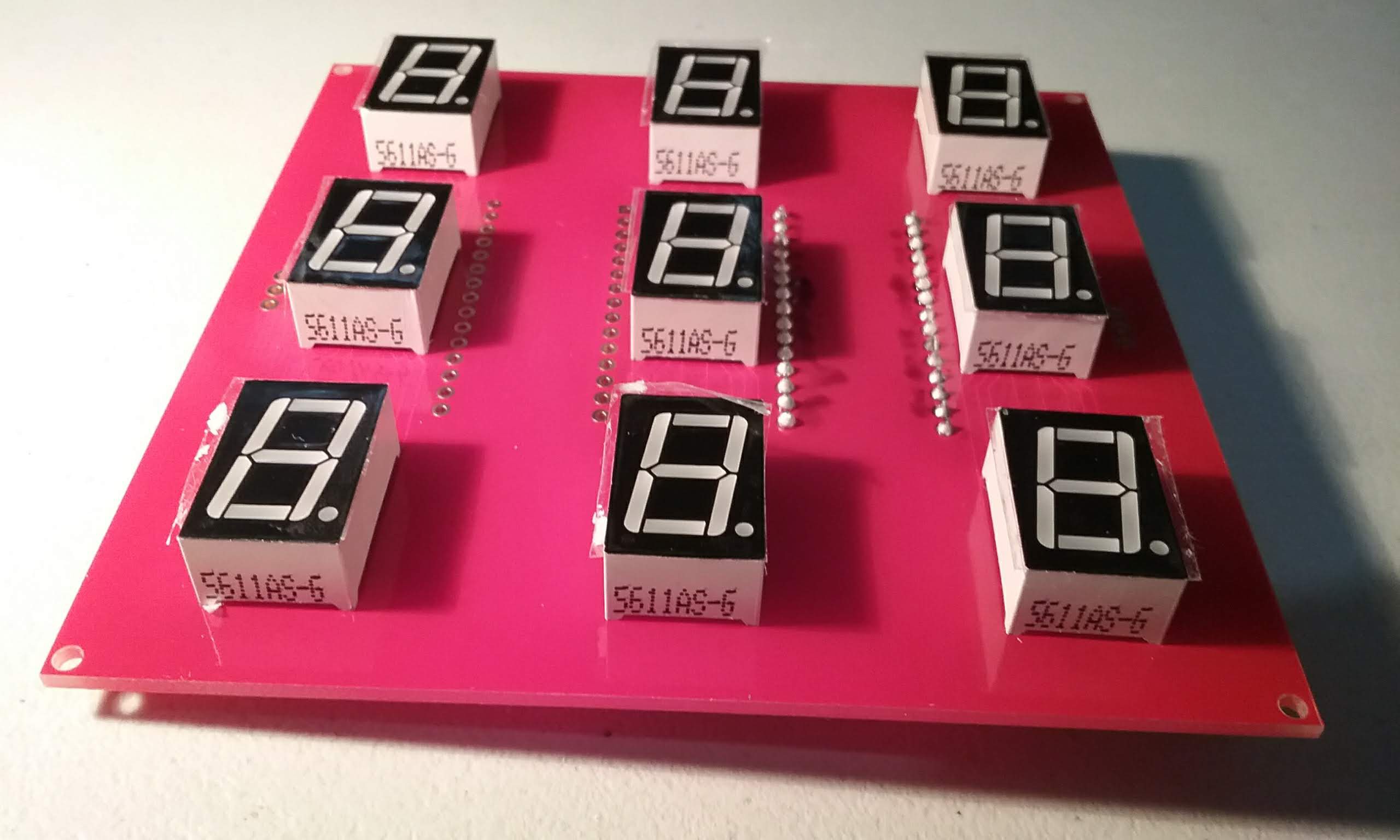
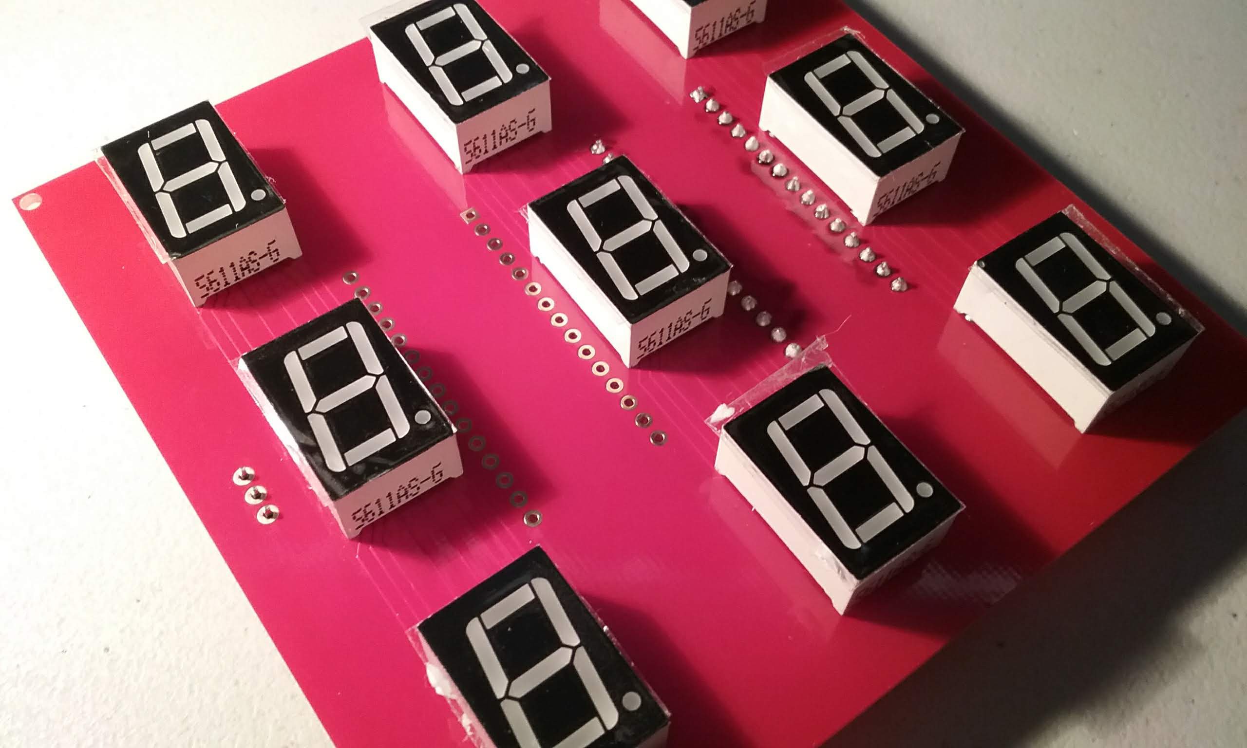
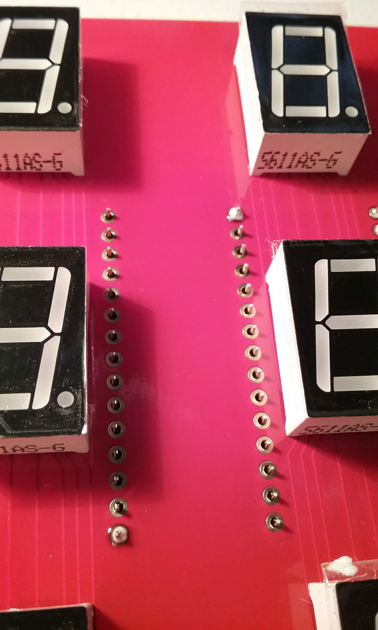
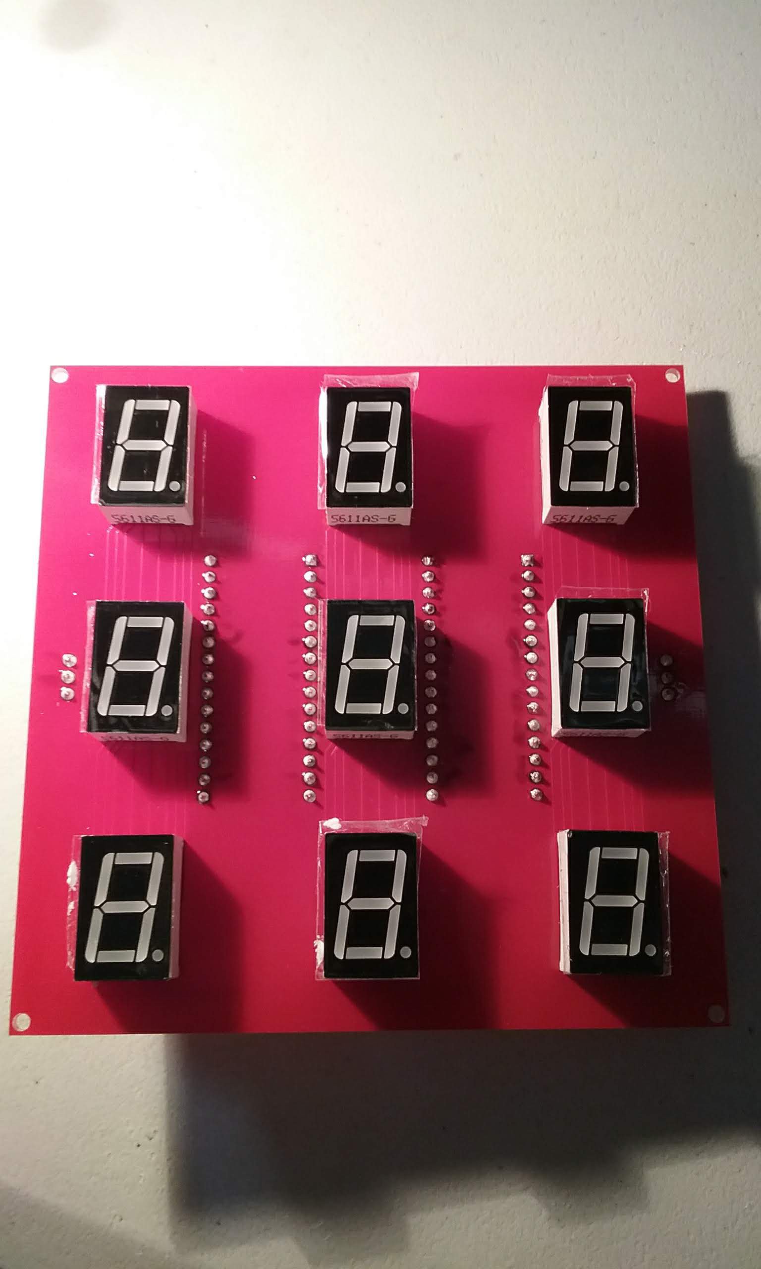
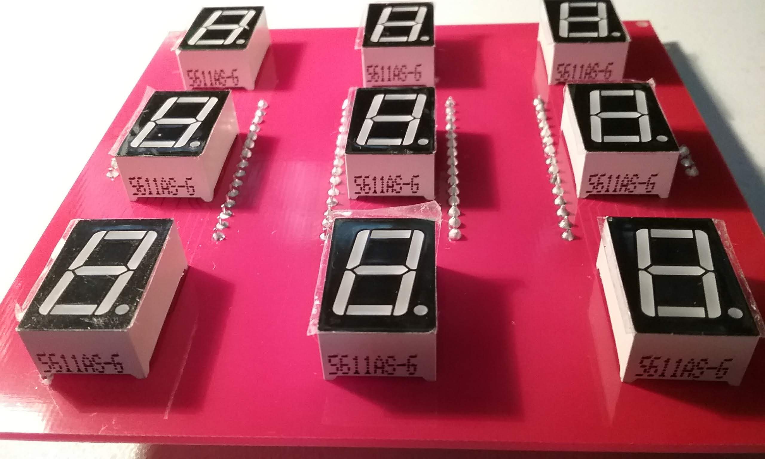
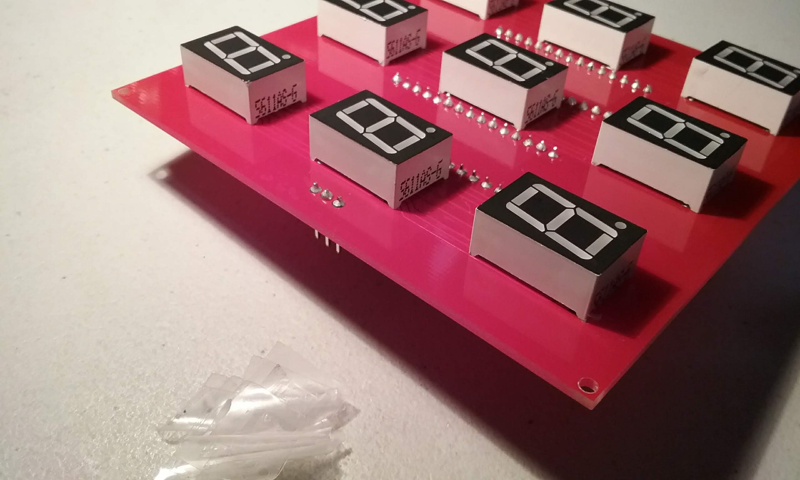
Next, insert the displays on the board. These have been pre-tested in a bread board to make sure all the segments work. Make sure the decimal point is facing down. Note that the display arduino is on the right half of the board.
Carefully (the displays fall out easily), flip the board.
While pressing down on the board, solder one pin on each display.
Flip the board and make sure the displays are sitting flat.
Then finish soldering the rest of the pins.
Make sure all the pins are soldered and no solder bridges exist.
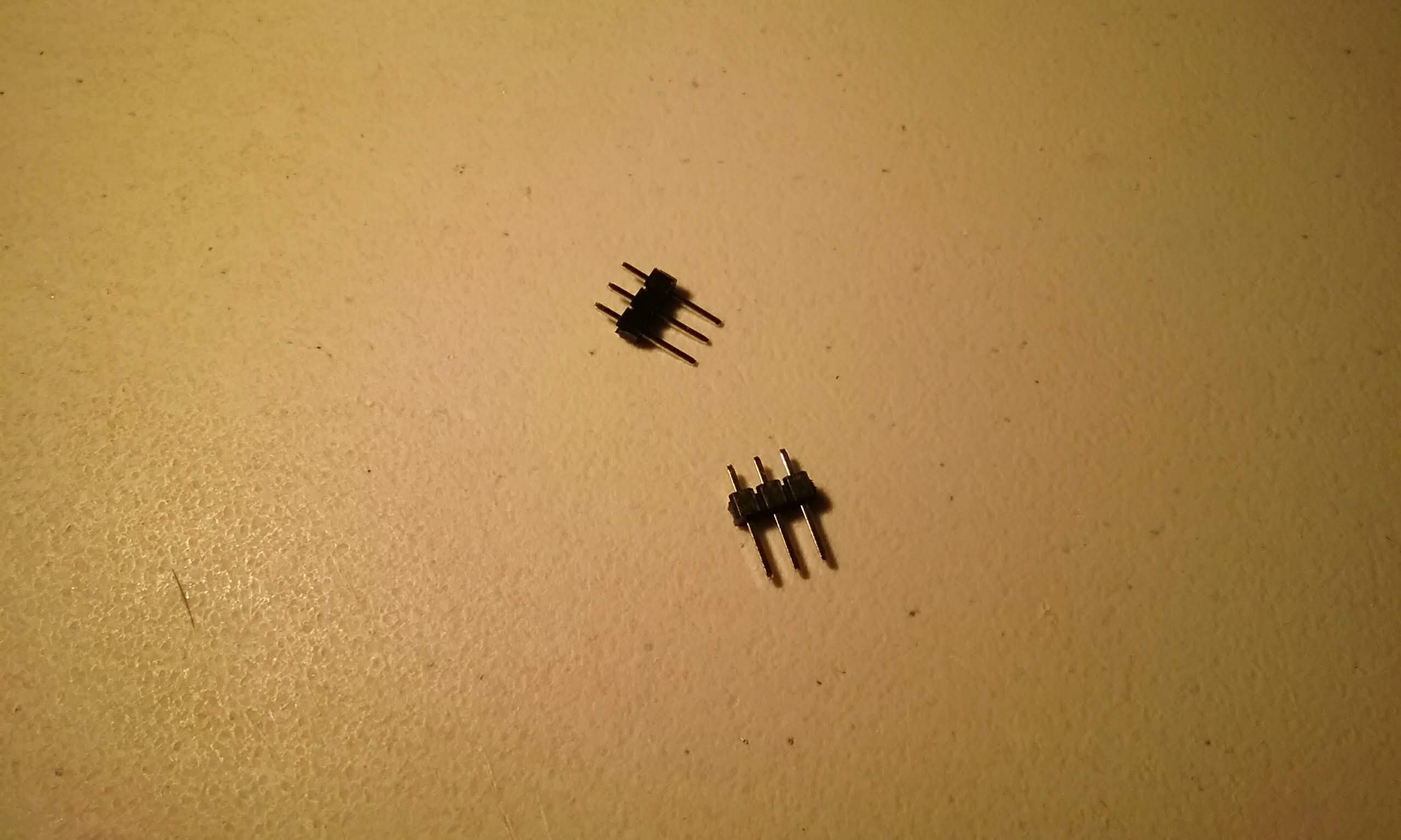
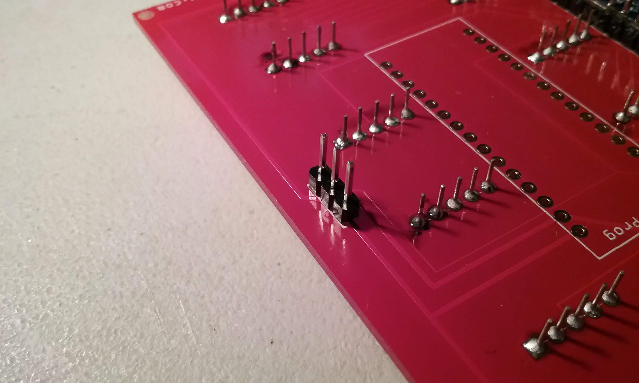
Next, prepare a pin header, we need 2 three pin headers.
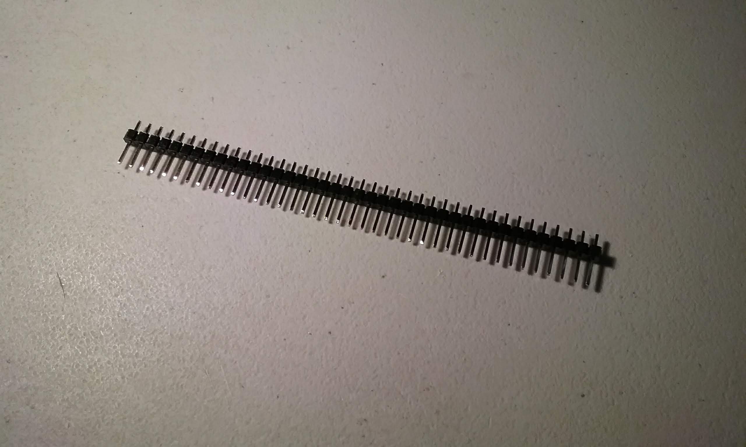
Break off two three pin headers.
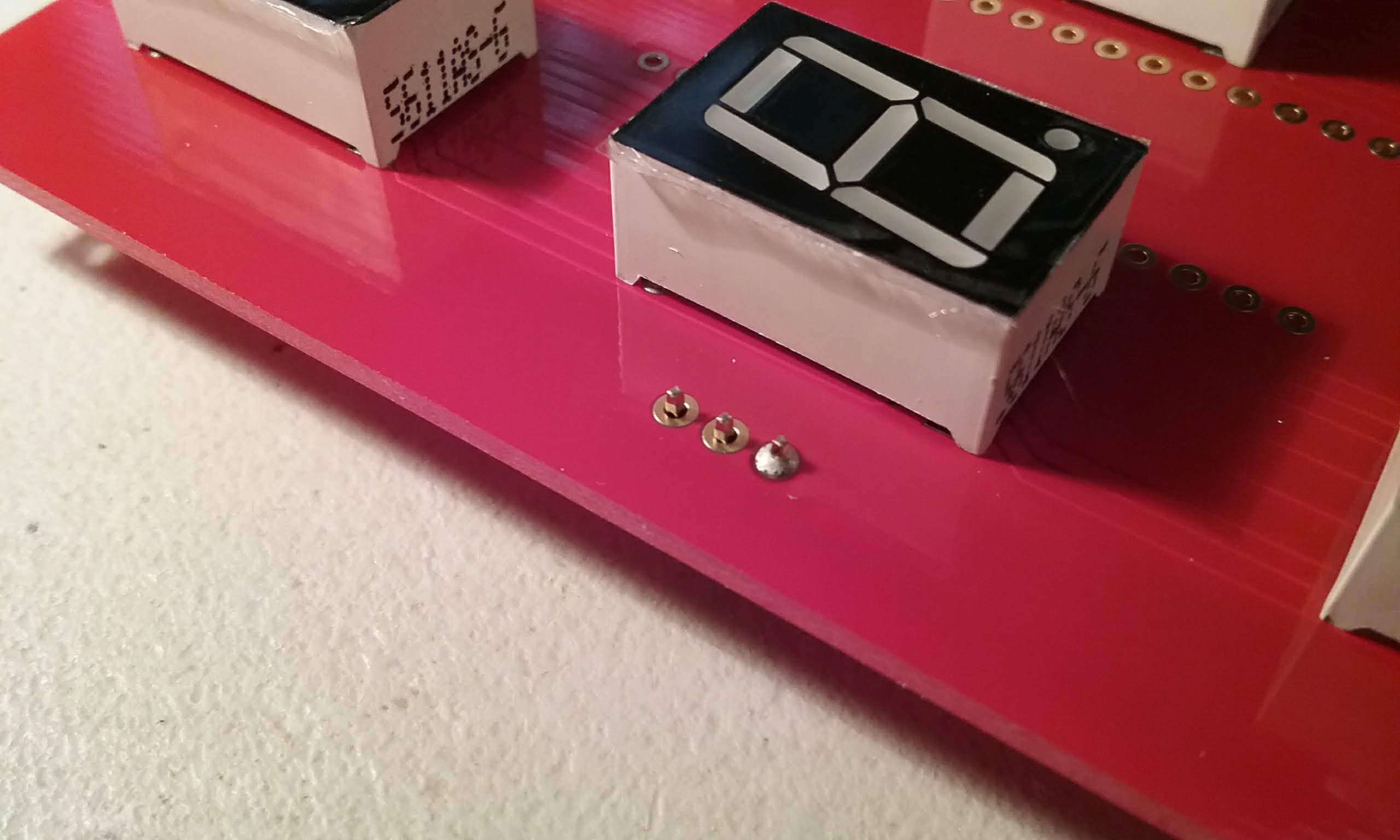
Place the short end on the bottom side of the board.
Carefully flip the board, ensure the pins are sitting straight.
Solder one pin.
Make sure everything is sitting straight.
And solder the rest of the pins.
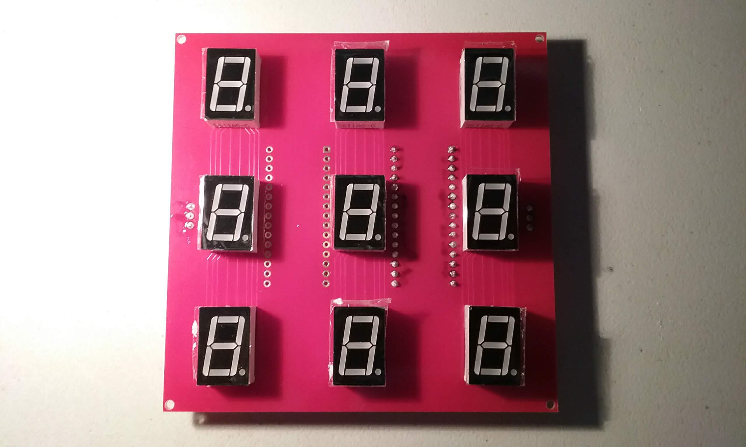
And here is a fully soldered tile board. The steps after this one are to make a master tile.
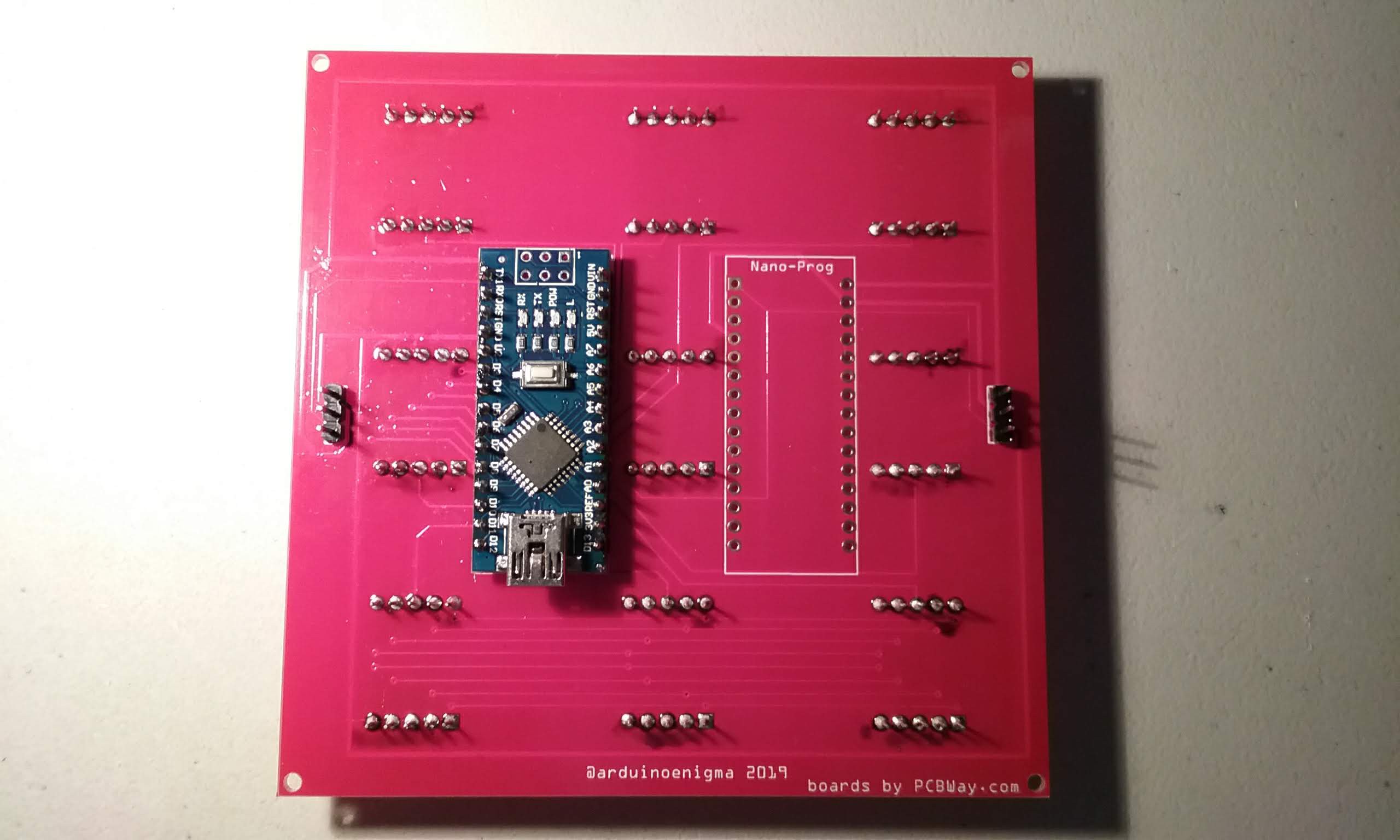
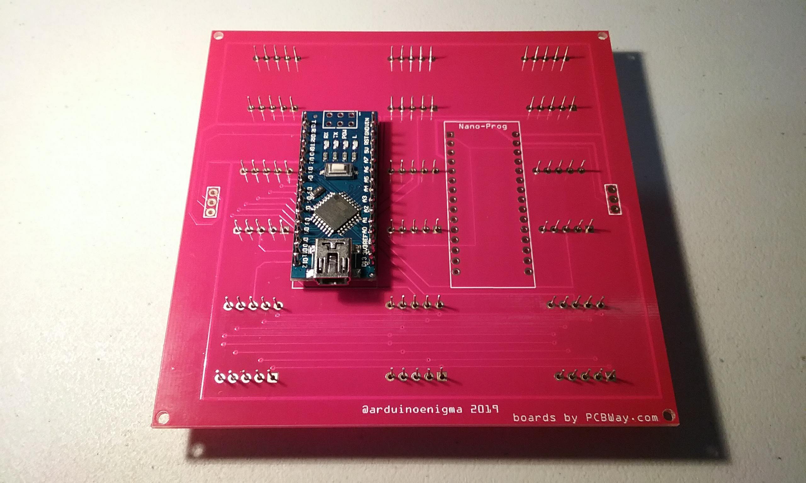
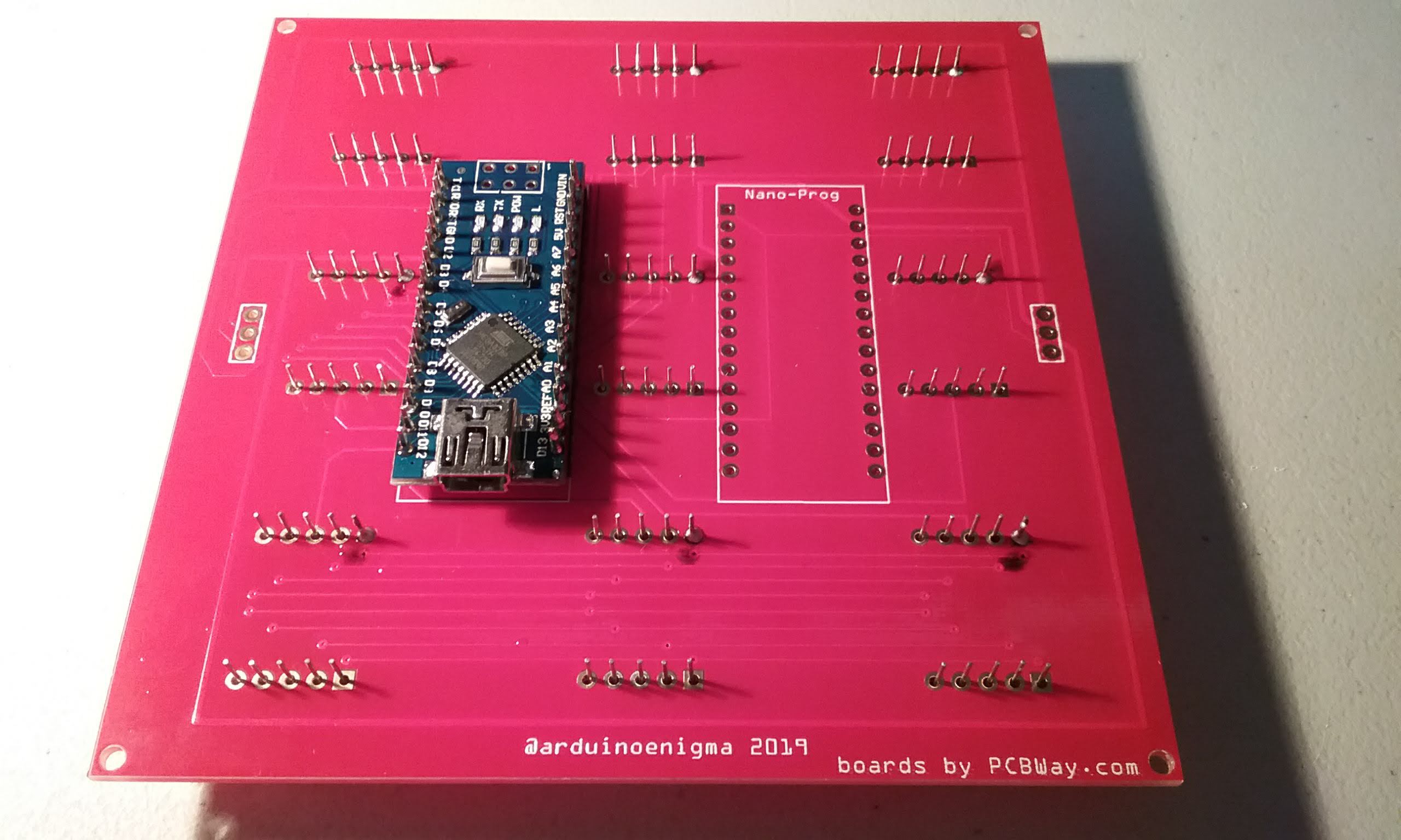
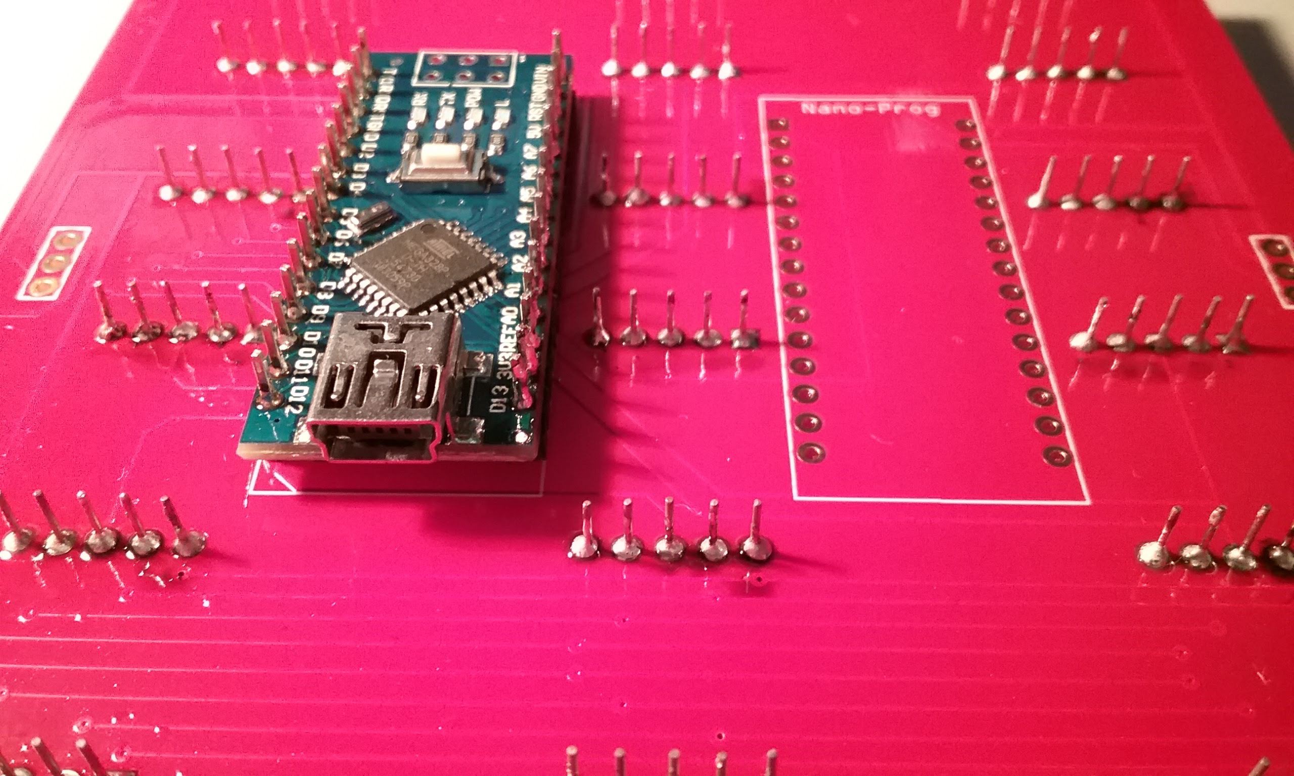
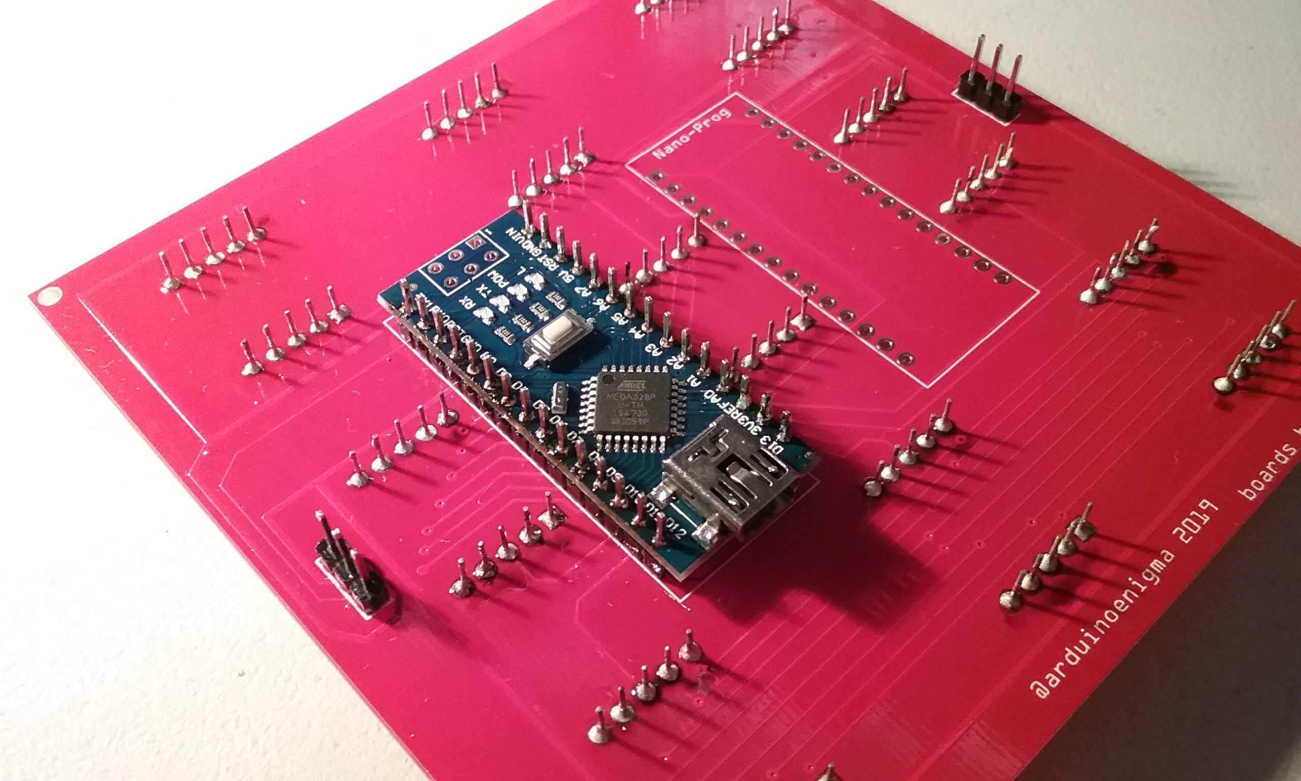
To make a master tile, start by placing the female headers on the bottom side of the board on the footprint labeled Nano-Prog.

Insert the Arduino Nano on the headers.
Press everything down to ensure the pins are fully seated and solder the four corners.
Flip the board and solder the corners on the headers. Be careful that the soldering iron does not touch the displays.
Flip the board over.
And solder the rest of the pins.
Flip the board and solder the rest of the header pins.
Next, using a toothbrush and water, clean the flux from the board. Looking good!
This is what the board will look like once cleaned.
The front looks symmetric.
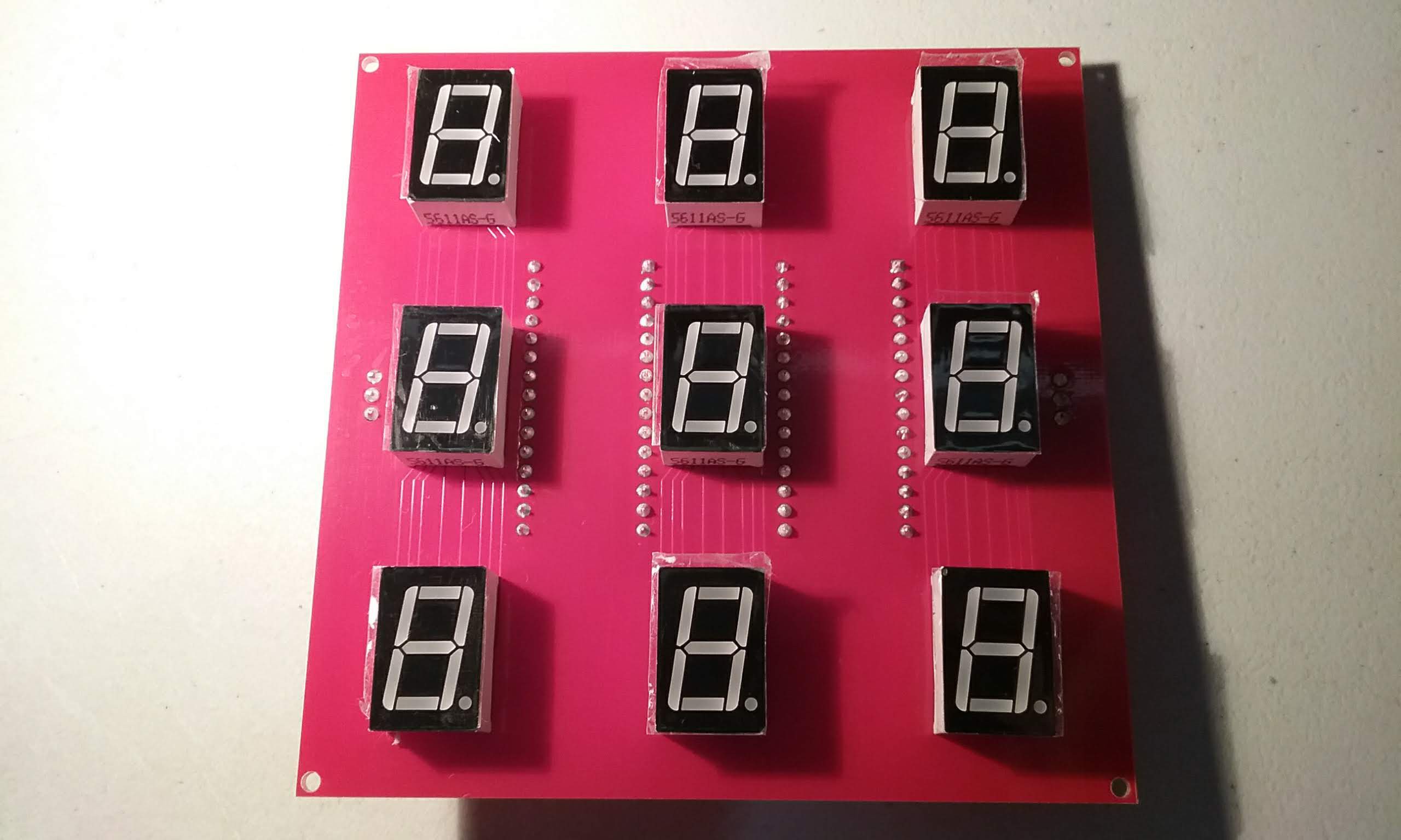
Looking good.
The last step is to peel the stickers from the displays.
The next step is to program the board.
Load this sketch into the tile.
https://gitlab.com/arduinoenigma/seven-segment-art-installation/tree/master/Board100x9x13
Hold down the reset button on the Nano-Prog Arduino while programming to prevent it from loading down the Rx line. If the tile software has to be reloaded, hold down the reset button on the tile before the one being programmed to make its TX pin go to high impedance and not interfere with the programming.
Load this sketch into the Nano-Prog Arduino, since it is the first on the string and there is nothing connected to its Rx line, it can be programmed normally.
https://gitlab.com/arduinoenigma/seven-segment-art-installation/tree/master/Board100x9x13-Master
Next is to put standoffs on the board, mount them to a base and wire them.
Discussions
Become a Hackaday.io Member
Create an account to leave a comment. Already have an account? Log In.