It's been nearly 2 years since my last log, and things are quite different from where I left it. I've been poking around at this project in between other projects and university, so most of these details are not recent. I found out that there has since been some work-in-progress commits on the coreboot Gerrit (link) for another GM45 + DDR2 laptop. Some of the patches related to that included DDR2 ram initialization code, so I no longer have to worry about that task. I tried building and flashing coreboot with some of those patches, and to my surprise, the system actually booted!
However, my joy was short lived. About 30 seconds after powering on, the fan ramped up to full power, after which the system shut down. After some investigation and experimenting, I determined that the issue was likely not the code or my coreboot configuration. I suspected that the embedded controller (EC) was to blame, so I asked about it on the coreboot IRC server. Someone did seem to agree, suggesting that the EC was waiting for some sort of "system OK" signal.
So now I have to figure out if that is truly the case, and if so, how to fix it. The easiest way to do that is probably reverse engineering the original BIOS, but due to Dell's EULA and the laws that apply to me, I am fairly certain I would not be allowed to do that. Exploring other options, I figured the only thing I could safely do would be to sniff the Low Pin Count (LPC) bus that connects the EC to the rest of the system. I have a some ideas for doing that, but I'll probably save those details for a future log once I have an actual implementation of said ideas.
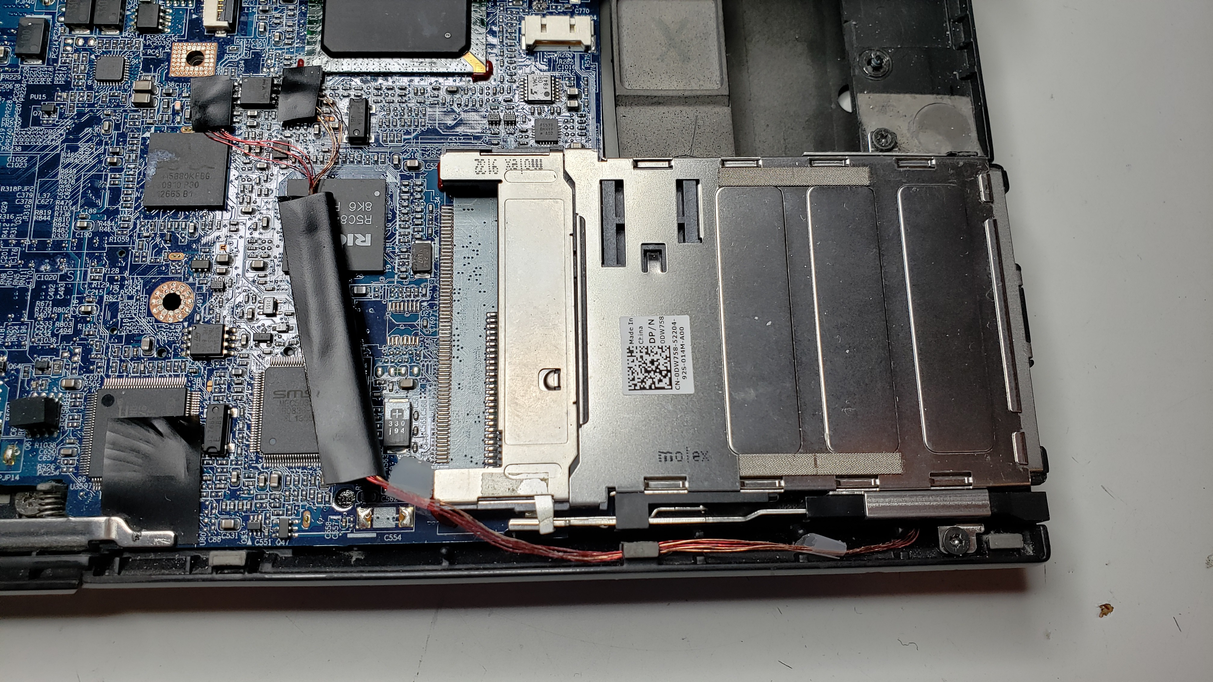
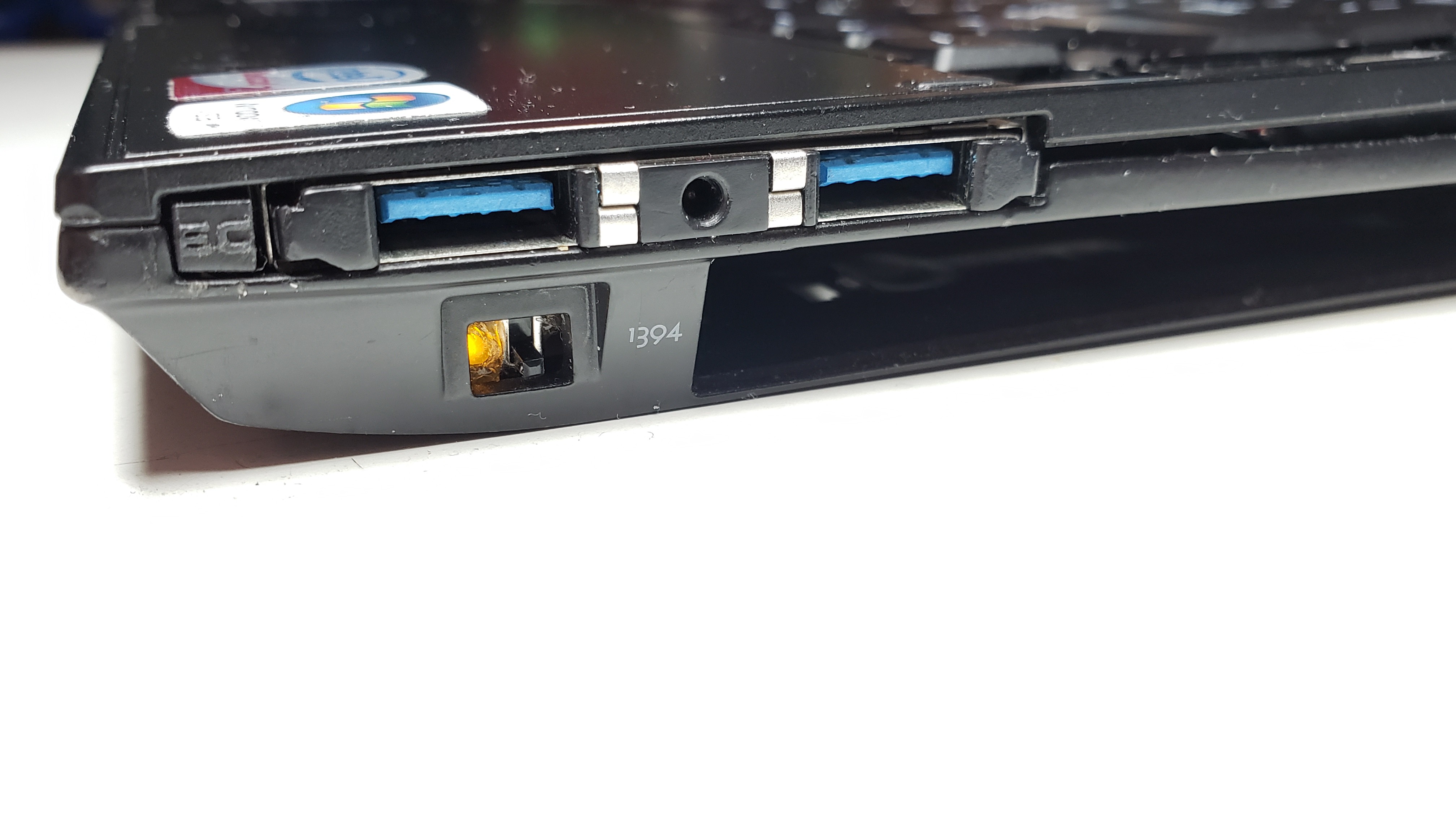
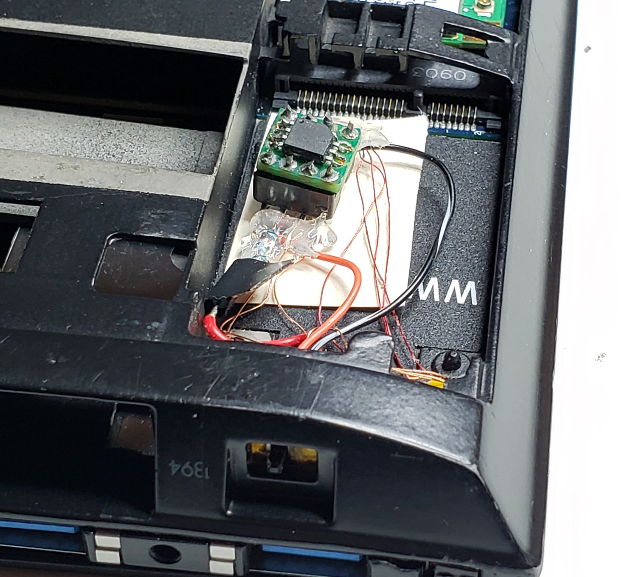
I've also made it much easier for me to flash the BIOS. I soldered some enamelled wires from the SPI flash chip on the top side of the motherboard to a DIP-8 socket in the unused wireless modem bay. I also removed the Firewire port and cable and replaced it with a switch that allows me to select either the internal SPI chip or the socketed SPI chip too boot from. An LED provides visual feedback on which chip is selected. Instead of disassembling the entire system, I can now just pop off the bottom panel, which only takes a single screw, and easily remove the DIP flash chip for external programming.


 Nicholas Chin
Discussions
Become a Hackaday.io Member
Create an account to leave a comment. Already have an account? Log In.
Well done, it's amazing that you get so far yet! Have you worked again on this project, since 2021? I didn't find your repo on Github, could you provide the link?
Happy hacking (a X230T-librebooted user, interested in flashing a friend's E6400)
Are you sure? yes | no