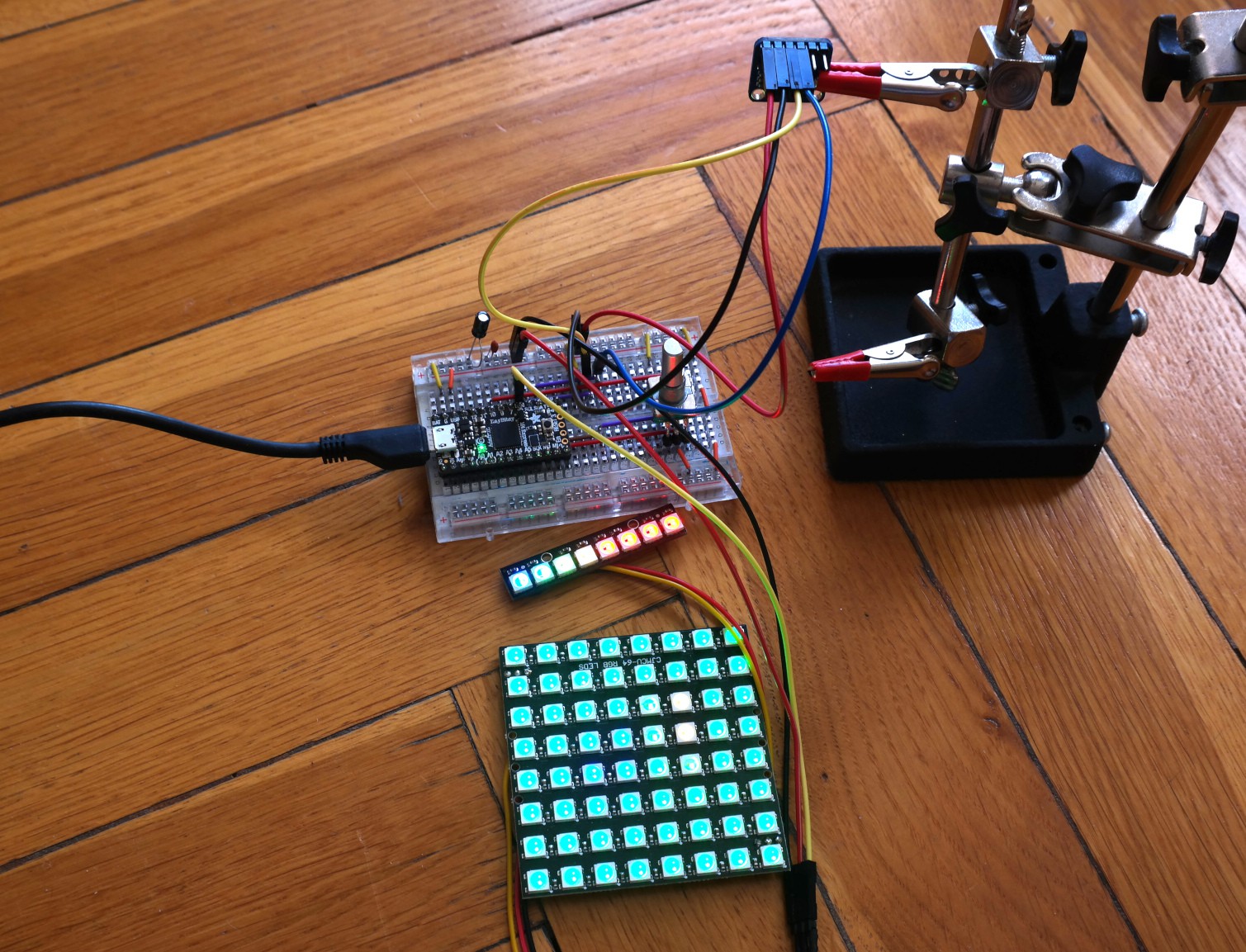
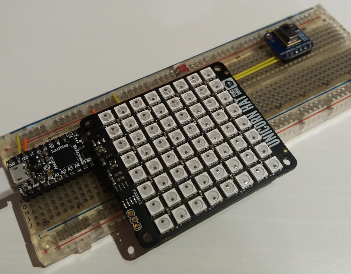
Close
0%
0%

No point IR camera

There are point and click cameras, but there is no point in existence of this one

Similar projects worth following
Virtually useless IR camera consisting of CircuitPython compatible microcontroller, AMG8833 IR temperature sensor and 8x8 NeoPixel matrix. Build for fun, to learn CircuitPython and justify buying even more electronic components.

I was looking for a project to get used to using CircuitPython for my tinkering. I decided to build an IR camera with AMG8833 sensor, which I recently bought for testing. For a display I went with 8x8 NeoPixel grid, which is an obvious choice when you take into account that sensor measures temperatures in 8x8 grid as well. As for the brain I chose Adafruit ItsyBitsy M4 Express, but I will also want to check if a board with M0 microcontroller will be sufficient for this task.

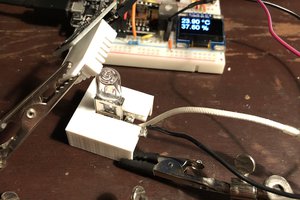
I don't have any real use for this device, although I can imagine it can be used for example to look for thermal leaks. To wet the appetite I hacked together test circuit on a breadboard and wrote some code, which does not behave as I expected. But for a start it's more than enough. Main project photo presents my selfie: three red(-ish) pixels in the middle are my face and remaining few at the bottom are my hands (with phone in right one).

Project goals:

1. Build a battery powered IR camera with LED matrix display using microcontroller supported by CircuitPython.

2. Write software to map temperatures to RGB colour values.

3. Test how capable are SAMD51 and SAMD21 microcontrollers in running CircuitPython programs with quite a lot of calculations.

4. Design and 3D print enclosure.

  • Problems & solutions

    Szaja04/13/2019 at 05:26 0 comments

    It's really confusing when your project just stops working overnight by laying on a table. In my case it turned out that there was a short somewhere inside a breadboard resulting in LEDs flickering. It took me over a week to debug this.

    There is an issue with the library which I use for IR sensor. Datasheet defines that measured temperatures range is from 0 deg. C to 80 deg. C. It's not really true, as you can also get negative values, which result in variable overflow. As I have only 8 LEDs for temperature scale I decided to stick with default range from 0 to 80 deg. C. and cut any values above or below. But I will try to investigate if it will be possible to improve how library works.

    Lastly, I changed button used to change temperature scale for a rotary encoder. There is a ready to use Adafruit library for this component as well, so it was really easy to do. Now the temperature scale is changed by rotating encoder left or right, which is much better than using a button for iterating over 8 values. Moreover, as encoder also has a button, I implemented a feature to send map of temperatures over serial port. So it will be possible to capture images when device will be connected to a PC. Cool! It may be a little bit less useless after all!

    I planned to make a comparison between ItsyBitsy M0 and M4. Right now I'm using only M4 version, because there is a problem with not enough memory in M0. The fact is that the code is really sketchy, as I'm rather a poor programmer and focus on making thing work more than being effective or elegant. But I will try to make some optimizations, i.e. do not use floating point values for calculations everywhere.

    As for right know all planned features are implemented, so I can move to power supply system and case designing. Here is the setup ready for test:

    I moved the camera from the breadboard to set the stage easier. For a test I took a slightly warm tea and a piece of frozen meat.

    Images are a bit dark to show colours of the LEDs. Here is the output:

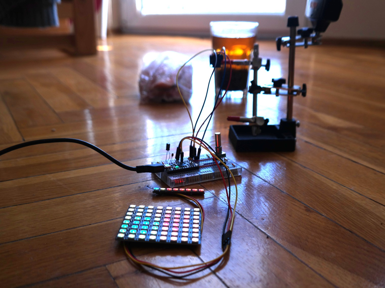
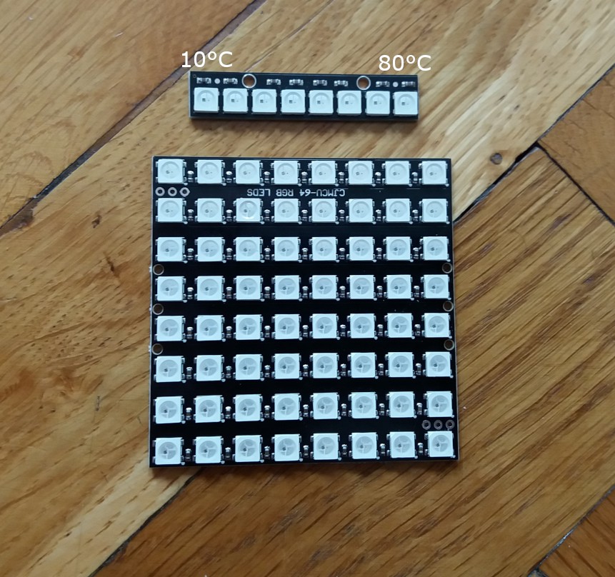
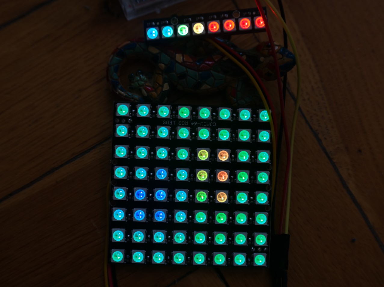
    You set the temperature map by rotating the encoder. Basically it moves the temperature which is shown as a full red (RGB 255, 0, 0). In this case it's 50 deg C, as 5th LED (counting from the left) at the line at the top is full red. Full blue (RGB 0, 0, 255) is always 0 deg. C and it's not shown, 1st LED is for 10 deg. C. So you can estimate, that the meat is really frozen (0 deg. C or below, as they are flattened), and the tea is somewhere between 40 and 50 deg. C. It works!
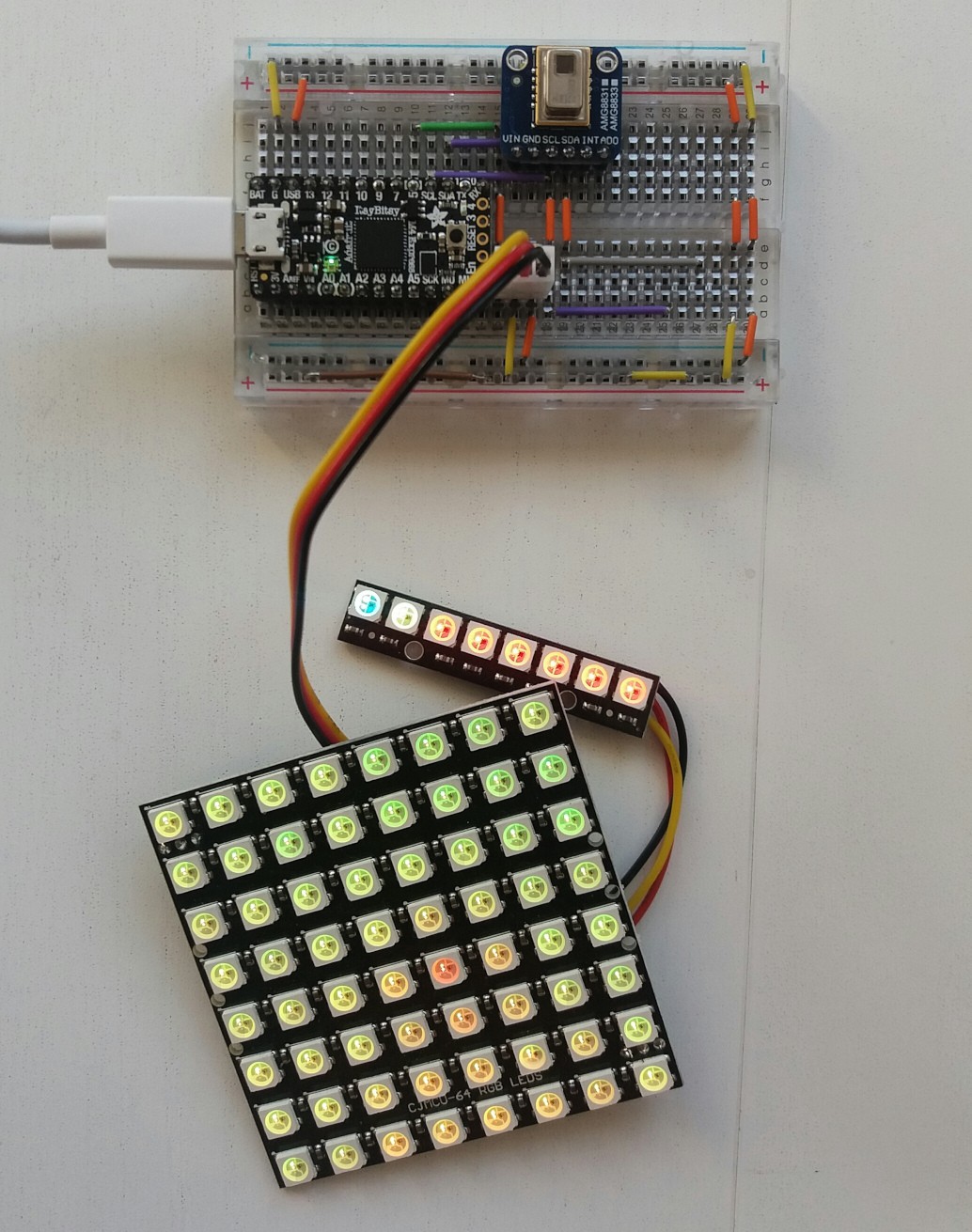
  • Map temperature to colour - part 2

    Szaja02/10/2019 at 22:10 0 comments

    I made some nice progress in last few days. First of all I rebuild the circuit on smaller breadboard using new LED matrix with additional 8 pixel strip. Connections are rather straightforward: IR sensor is connected to SDA and SCL ItsyBitsy M4 pins and LEDs are connected to pin 5. Afterwards I went back to code. I wrote a rather simply procedure to map temperatures to colours. First of all maximum represented temperature is defined, which will be displayed as red colour (RGB value 255, 0, 0). If sensor will measure higher temperatures than this defined value they will be also shown as red colour. Temperature 0 °C is represented as blue (0, 0, 255), and green is in the middle. Temperatures laying between these three values are linearly interpolated as mixes of two nearest colours.

    In the last step I added a button which allows to change maximum represented temperature value in range from 10 °C to 80 °C (which is a maximum for used sensor). Button is connected to pin 10 with internal pull up enabled. Colour to temperature legend is displayed on the previously mentioned additional strip of 8 LEDs: leftmost pixel presents colour for temperature of 10 °C and rightmost for 80 °C with the remaining values in between them. This allows user to estimate temperatures of visible objects by cycling through eight settings in search for optimal one for current conditions. Code is on GitHub.

    I should now move on to next steps in the project, but I got an interesting idea. I was trying to think out a way to make this device a tiny bit less useless. I realized that it might be quite fun to be able to save an image when device is connected to PC. To do this I plan to replace the button with a rotary encoder, in which rotation will cycle through temperatures to colour map modes and click will trigger data export by serial port. Then Python script can be used to export an image (in 8x8 resolution or higher with interpolation).

    I also learned something the hard way. It's really hard to take a photo or record a movie of light up LEDs. Still no solution to that, but I will do my best to solve this issue.

  • Map temperature to colour - part 1

    Szaja02/03/2019 at 10:47 0 comments

    I'm trying to solve the problem of mapping temperatures to colour scale. Initially I came up with two ideas, but both where far from perfect:

    • create a map where temperature 0°C will be blue, 40°C green and 80°C red with mixing between them
    • find minimal and maximal temperatures from current set and display them as blue and red, accordingly, with green in the middle and mixing between them

    In the first case the problem is that when there are small differences in temperatures colours of pixel are nearly the same. In the second case the problem is that temperature scale is changing in real time and user doesn't know what is the temperature of visible objects.

    To solve this I came up with an idea to mix these two solutions: add even more LEDs (this is always a good solution to every problem) and a single button to create a user interface. Eight additional LEDs will allow to present current mapping of colours to temperatures, while button will allow to set which temperature will be presented as hottest (red).

    Moreover, I ordered a matrix of LEDs which will be easier to interface with microcontroller than Unicorn HAT.

  • Breadboard-based selfie camera

    Szaja01/26/2019 at 13:39 0 comments

    There is no better start than fast one with quick success. Luckily I had all the components for the first prototype of the camera readily available: besides AMG8833 IR sensor I took Adafruit ItsyBitsy M4 Express and Pimoroni Unicorn HAT (which of course is not breadboard compatible, but using some goldpin headers I was able to stick it in without shorting any signals).

    For ease of development power is supplied from USB 3.0 fast charging port from my laptop and up to now there was no problem with that. Nevertheless good tip is to look for a brightness setting in NeoPixel driving library to both save current draw and your eyes. These LEDs are really bright, so I set brightness value for no more than 0.1.

    As for the code I utilized readily available libraries for NeoPixel driving and IR sensor communication from Adafruit. Only challenge to get it going was to write some code to convert temperature values to LEDs colours. I had an idea how to do that, but somehow failed to convert it into working code. I mean code does work, but not as I was expecting. Nevertheless one of the strong points of CircuitPython came in for the help. I was able to find by a try and error method value for crucial variable used by my code to give more or less satisfying results on the output. It was really easy to do, because code restarts when you save a file stored on the device. That's handy. I will go back to that later.

View all 4 project logs

Enjoy this project?

Share

Discussions

Similar Projects

Does this project spark your interest?

Become a member to follow this project and never miss any updates