The BippetyBoop is my first entry in the 555contest. (Video at the bottom of this post)
It's a random tone generator sounds a little bit like the sound effects that 60's and 70's move producers liked to have when a large computer with a a lot of flashing lights was computing something. The timbre of the sound is not right since it's just a plain square wave, but the pitch and speed is not too bad :)
The circuit consists of four 555 timers, one 324 quad opamp and one 4016 bilateral analogue switch.
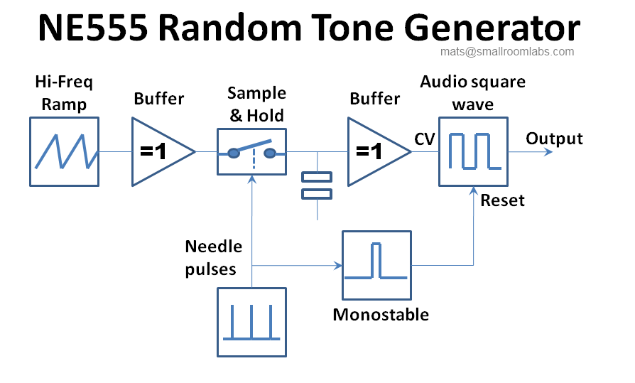
The block diagram below shows the basic function of the circuit.

The first 555 is used to generate triangular/ramp waveform. Instead of using the regular output at pin 3 I take the signal from pin 2 connected to the timing capacitor charging up and down during the cycle.
In order not to affect the charging of the capacitor this voltage need to be buffered by one of the opamps in the 324 set in a regular voltage follower configuration before it can be used by the rest of the circuit.
This voltage is used to control the pitch of the output.
The second 555 is a needle pulse generator I.E. a square wave with a very low duty cycle. The pulses are like a few milliseconds long and repeated at about 2 Hz. These pulses determine the speed of the beeps - so here I got about 2 beeps per seconds.
The output of the needle pulse generator is connected to two things. First it's controlling one of the switches in the 4016 that allows the buffered voltage from the ramp generator to reach the holding capacitor during those few milliseconds when the pulse is high. When the pulse goes back to low the switch is opened and capacitor is isolated from the varying voltage and is keeping the value for a while.
Since the needle pulses are not synchronized with the ramp generator this means that the holding capacitor will have different random voltages changing two times a second.
To actually use this signal without affecting it a second voltage follower from the 324 is connected to the holding capacitor.
The other thing the needle pulse generator is doing is to trigger the third 555 that is configured as monostable timer. For each short pulse from the needle pulse generator the monostable will output a pulse that is about 300 mS long
The fourth 555 is the just a standard square wave oscillator at a frequency about 1KHz. The CV (Control Voltage) input of it is connected to the buffered holding capacitor so the frequency will change according to the voltage at the capacitor. The Reset input is connected to the output of the monostable so it will only produce sound during the 300 mS the monostable is active for each pulse.
All in all this will produce short random beeps at a rate of about two beeps per second.
C1-4: NE555 IC5: HC4016 IC6: LM324 C1,C5,C6: 100nF C2,C3,C4,C7: 1uF
R1,R2: 22k R3: 470k R4: 2.2k R5: 100k, R6,R7: 10k R8: 1k D1: 1N4148
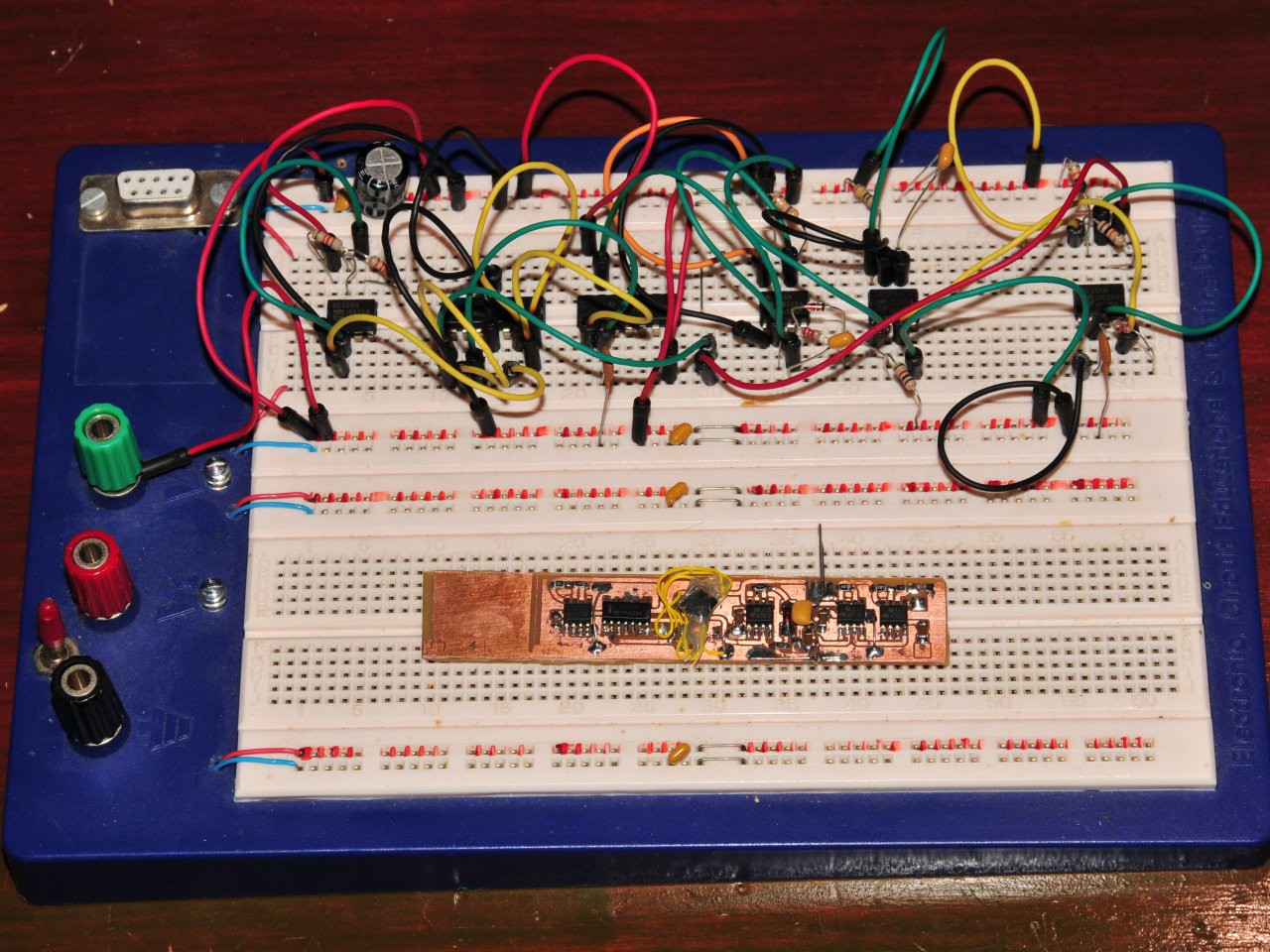
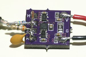
I first prototyped this on a breadboard using standard PTH components, then I etched a pcb for SMD components. Unfortunately I didn't have any SMD diodes at home, but a standard 1N4148 is small enough to be mounted as a SMD part quite easily. What was worse is that I discovered that I only had the 4016 in TSSOP version instead of the SOIC that I made the pcb for. I didn't feel like making another pcb so I just patched it in with a few old wirewrap wires and then put a glob of hotglue on top of it for stability.

And finally after all this jibba jabba - the video!
 matseng


 Ted Yapo
 Zach Armstrong
 Russell Kramer
 Hulk
Hulk
Wow! I remember making a random beeper like this around 1985 or so. It was built around a 555, but I don't remember what I used for the S/H. I do recall that the audio output was sampled as the new random voltage - so there were only two oscillators, the audio one, and one to generate the sample pulses. It sounded pretty random - sampling audio-frequency tones at up to a few times per second gets you a good random voltage. Just don't use very stable capacitors :-)