0%
0%
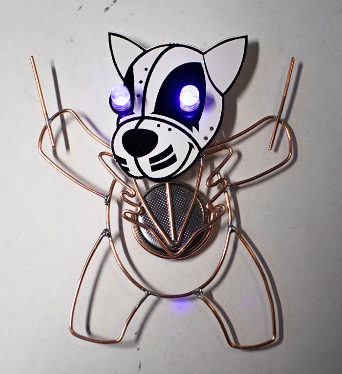
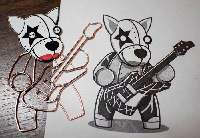
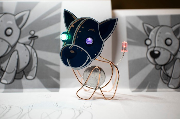
KISS Tindie Circuit Sculpture
A simple circuit sculpture project that gives copper wire frame bodies to KISS Tindies
 Roger
RogerBecome a Hackaday.io member
Already have an account? Log in.
Just one more thing
To make the experience fit your profile, pick a username and tell us what interests you.
Pick an awesome username
hackaday.io/
Your profile's URL: hackaday.io/username. Max 25 alphanumeric characters.
Pick a few interests
Projects that share your interests
People that share your interests


 (Cross-posted to

 (Cross-posted to


 (Cross-posted to

 (Cross-posted to


 Miroslav Zuzelka
 Gertlex
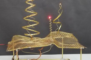
 Michael Aichlmayr
 Daniel Domínguez
+1