 Roger
RogerWith the wire spool ready to go, it’s time to tackle a simple starter learning project. For the subject I turned to the simple Tindie blinky badge. The badge itself is a soldering exercise, and now it will also serve as a freeform circuit exercise: I will give the Tindie puppy a copper wire body!
There will be two loops of wire, one will be electrically connected to battery positive, other loop will be connected to battery negative. There are two existing positions for LEDs on the badge, and I will be adding a third LED to give Tindie puppy a flashy tail. Each LED will bridge the two loops of wire for power.
The Tindie logo was printed up, scaled so printed head matches circuit board size. Then I start tracing out curves as nominees for positive and negative loops.

Once I had a plan, three segments of wire formed the positive loop, which has Tindie’s two left legs and most of the body.

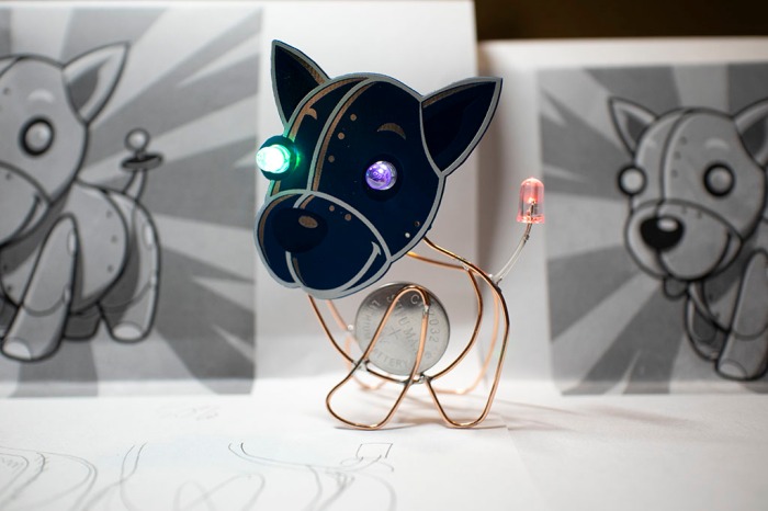
The negative loop has Tindie’s two right legs and some duplication of body curvature. I had to make sure it reached back far enough for the tail LED to get power. The two loops also formed a battery holder between them. It was important for the battery to be in the body if I wanted Tindie to sit on paws, because if I used the default battery holder in the head our puppy would topple over from being too top-heavy. And the natural place to put a battery in the body is in the chest, as heart of the machine.

Some soldering work later, Tindie is standing on paws of a shiny copper wire body, complete with blinky tail. Since the two loops of wire are only held together by leads of the three blinking LEDs, it is rather fragile. For future projects I need to find additional ways to brace positive and negative loops without short circuiting them. Either more electronic components or non-conductive structure.
(Cross-posted to NewScrewdriver.com)
Discussions
Become a Hackaday.io Member
Create an account to leave a comment. Already have an account? Log In.