New project page
Landbeest has evolved into Tardygrade. Follow the link to see recent updates on this project.
Motivation
I've previously tried building a couple of two-wheeled robots with the intent of having them drive around my apartment unattended. However that hasn't usually worked out as well as I'd hoped. What tend to happen is that the robot gets stuck on something after a minute or two, and I'll have to go rescue it. Usually the stumbling blocks are obstacles that aren't easily detected by sensors: carpet edges, door thresholds or wires.
Goal
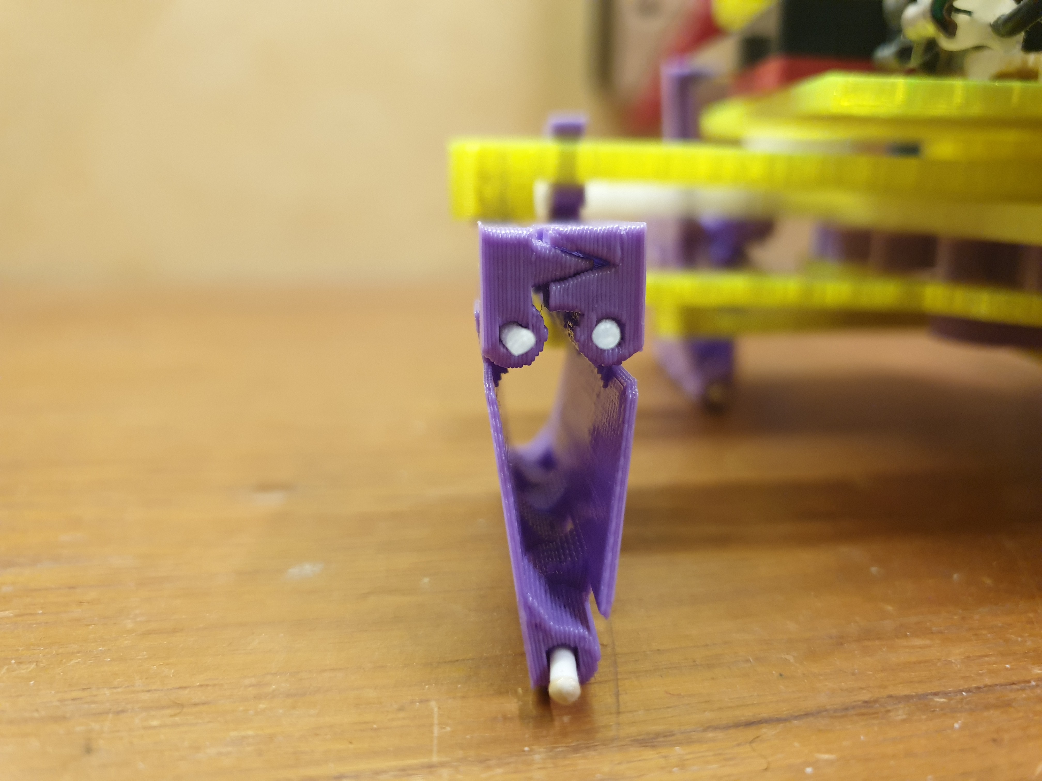
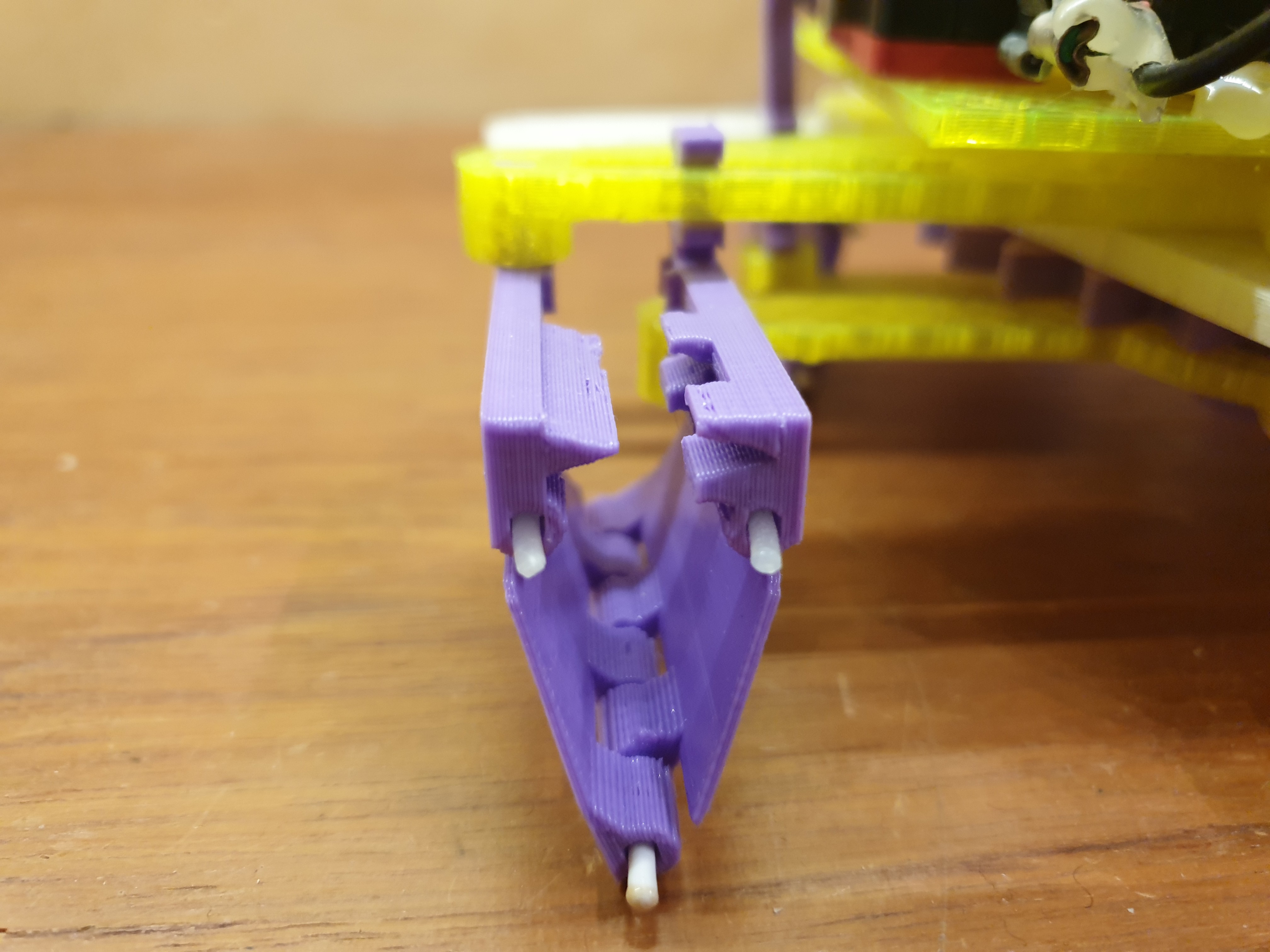
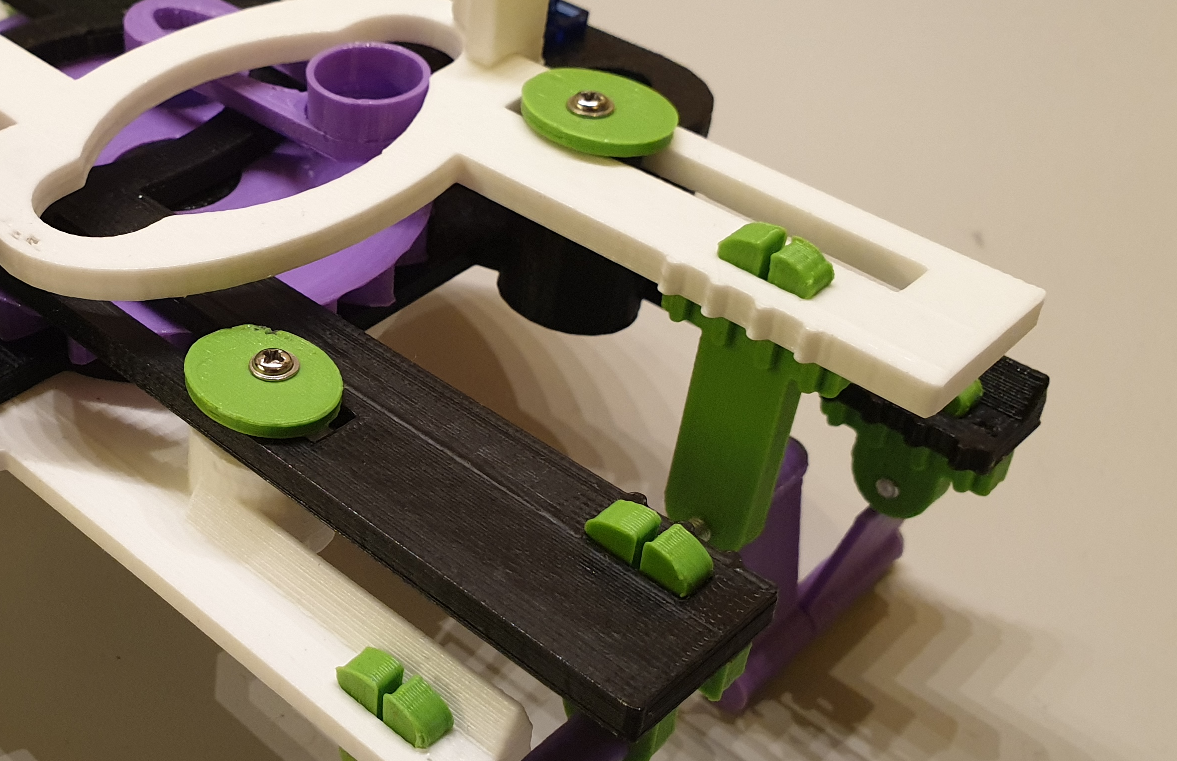
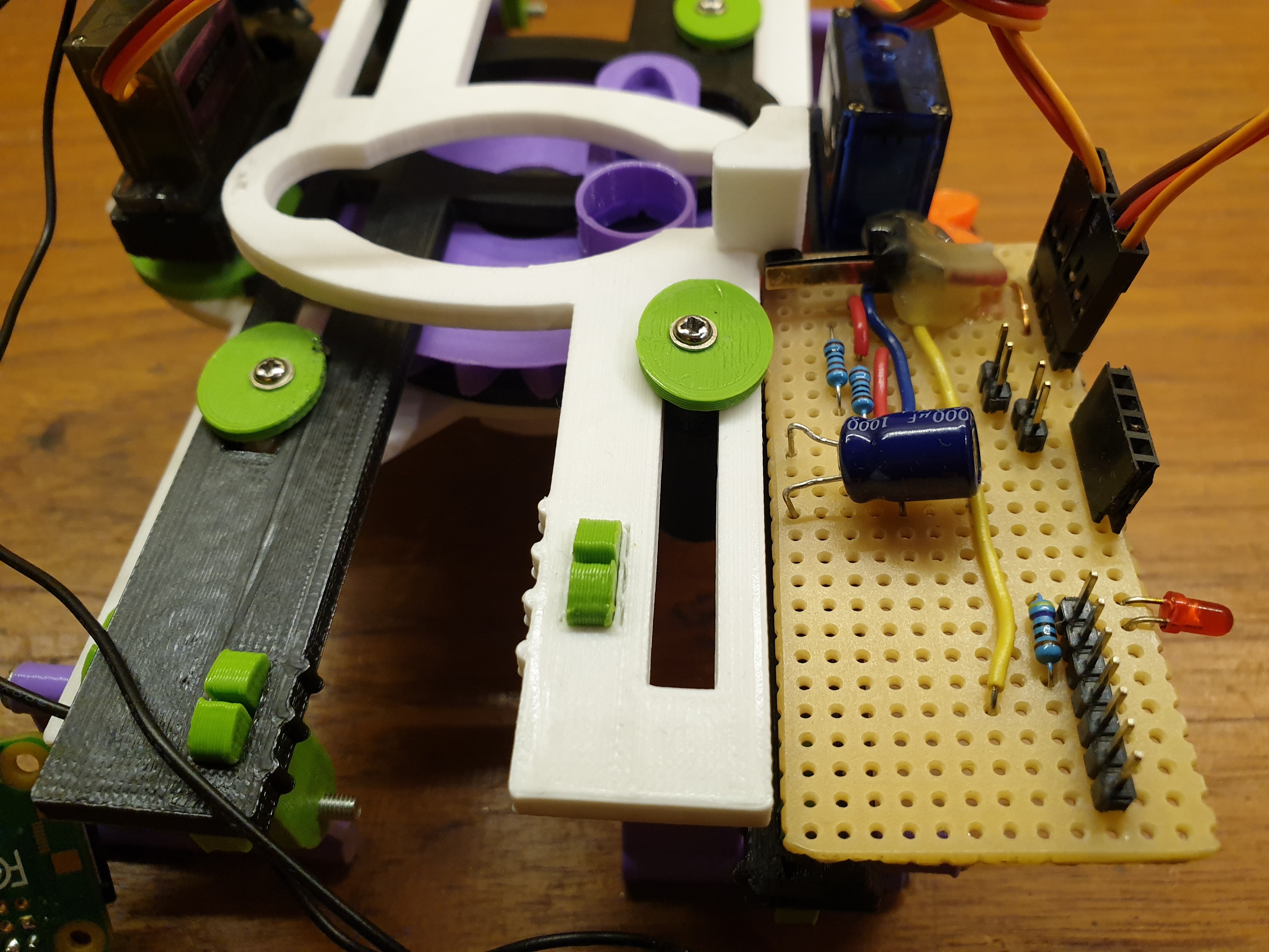
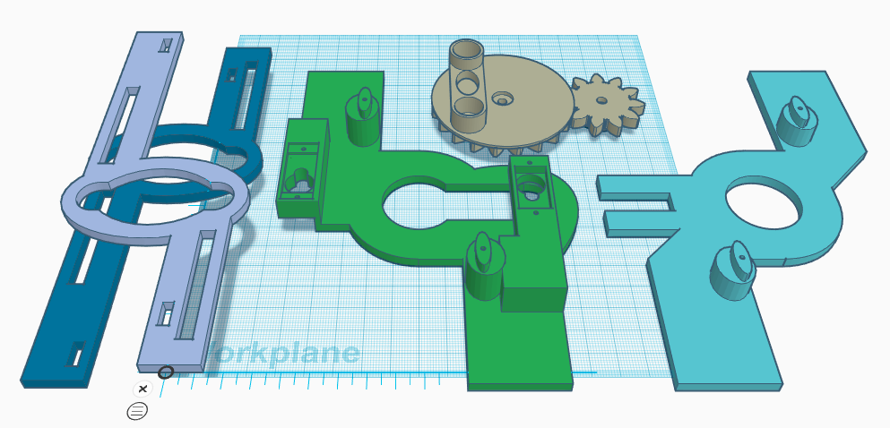
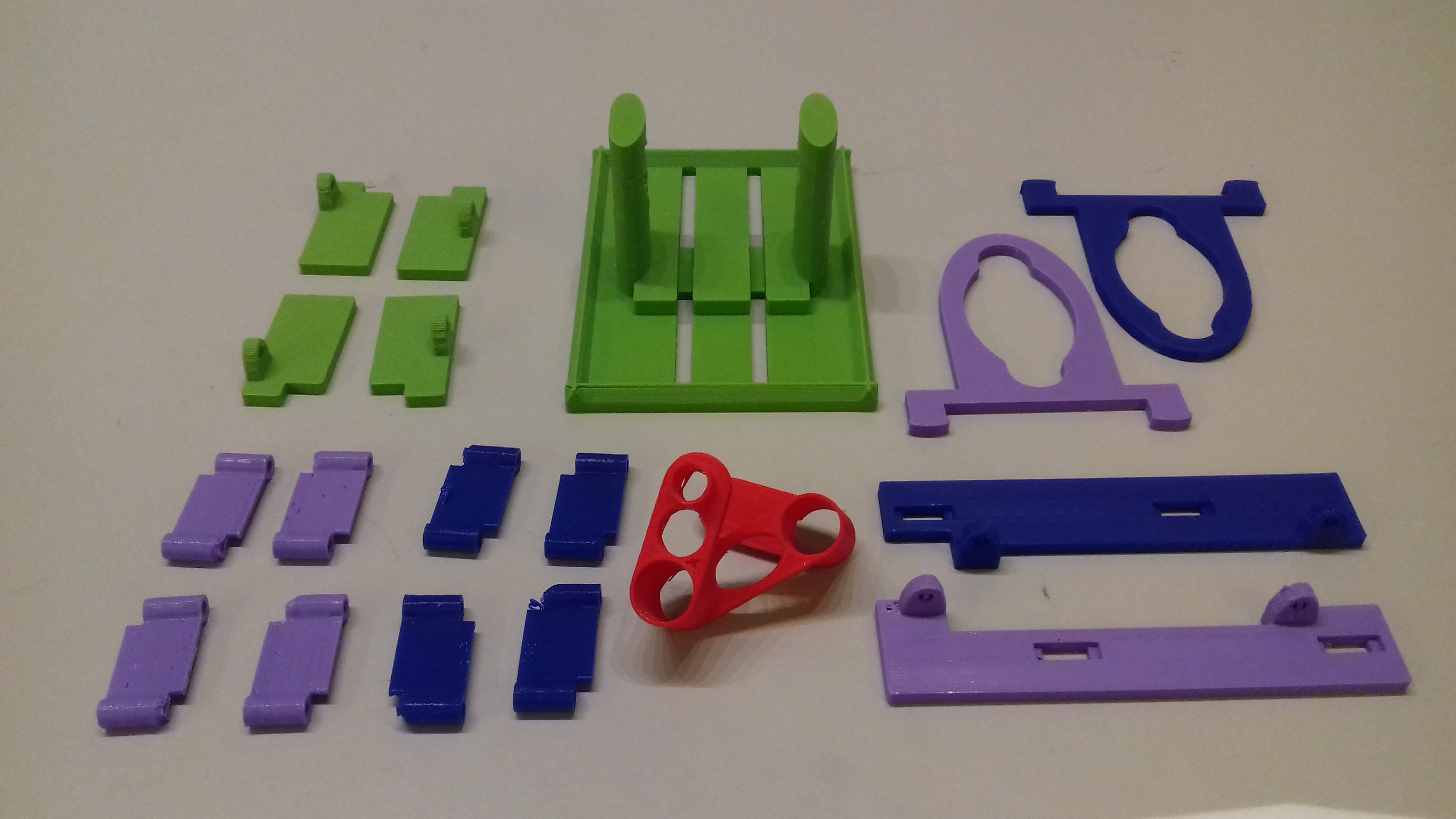
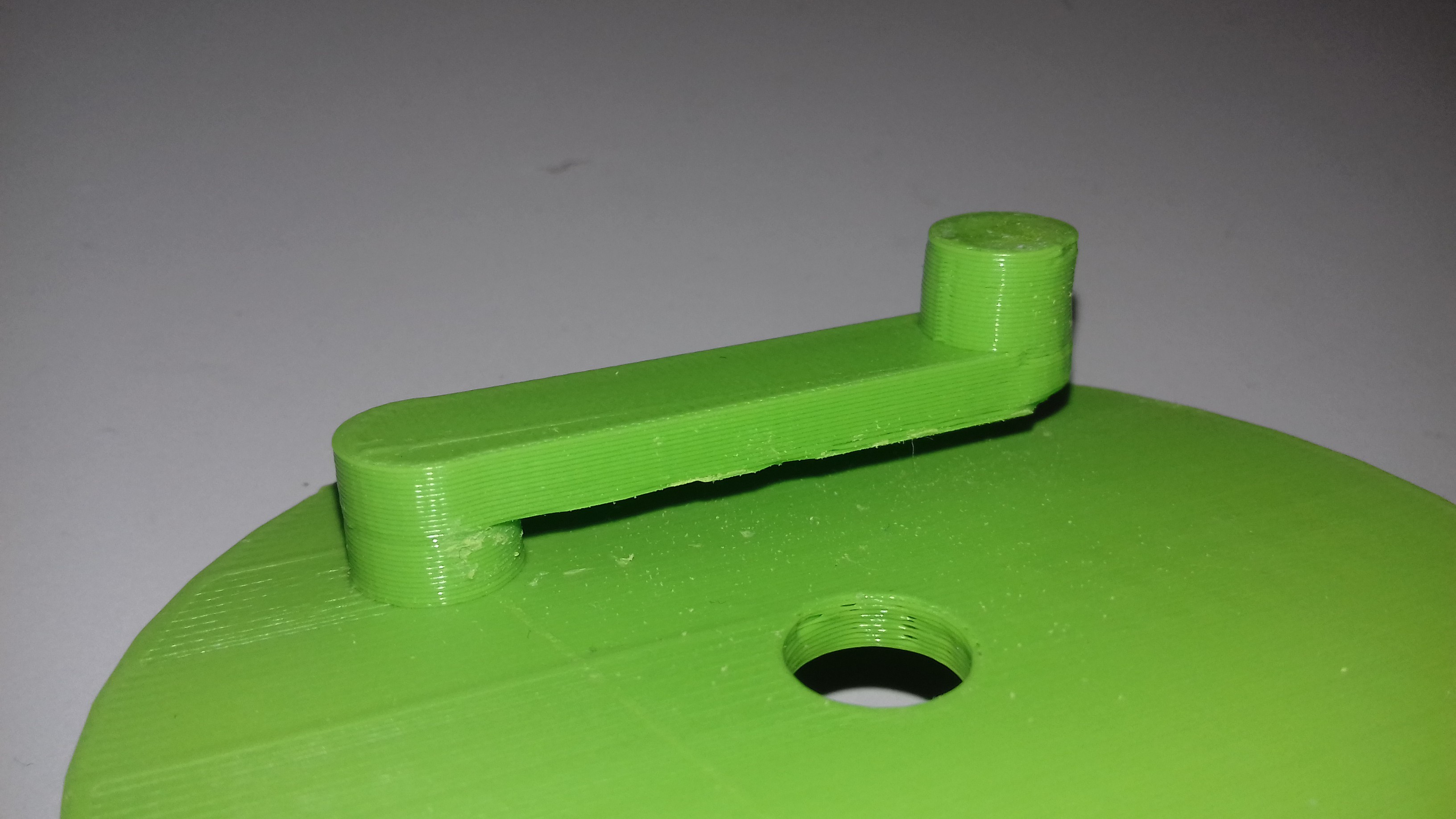
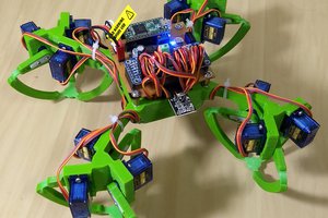
I want to design a quad walker robot platform that is really simple to build and is suitable for negotiating living room floor terrain.
Once I've arrived at a design I'm satisfied with I will publish stl files for 3D printing, buid instructions and code examples.
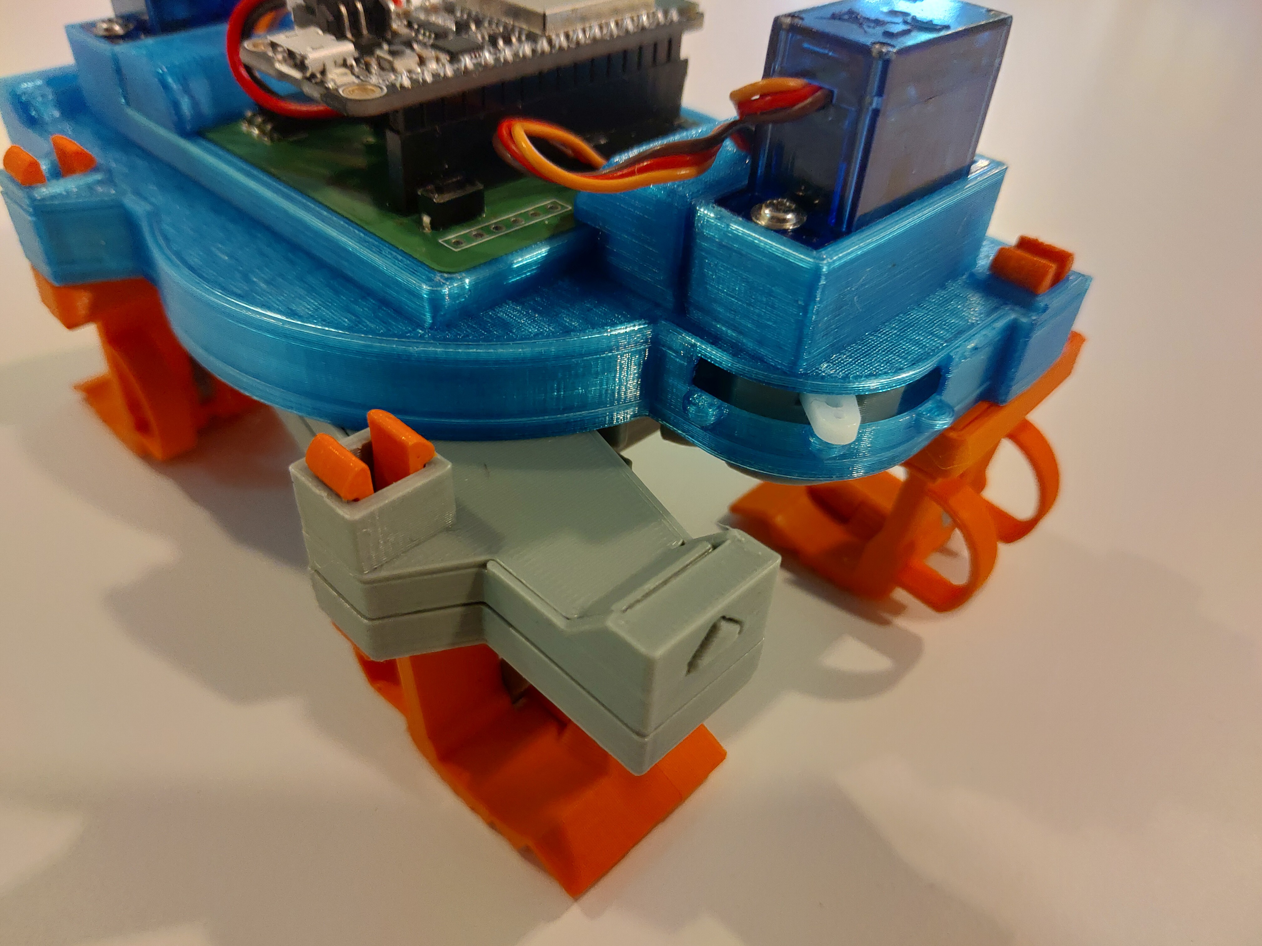
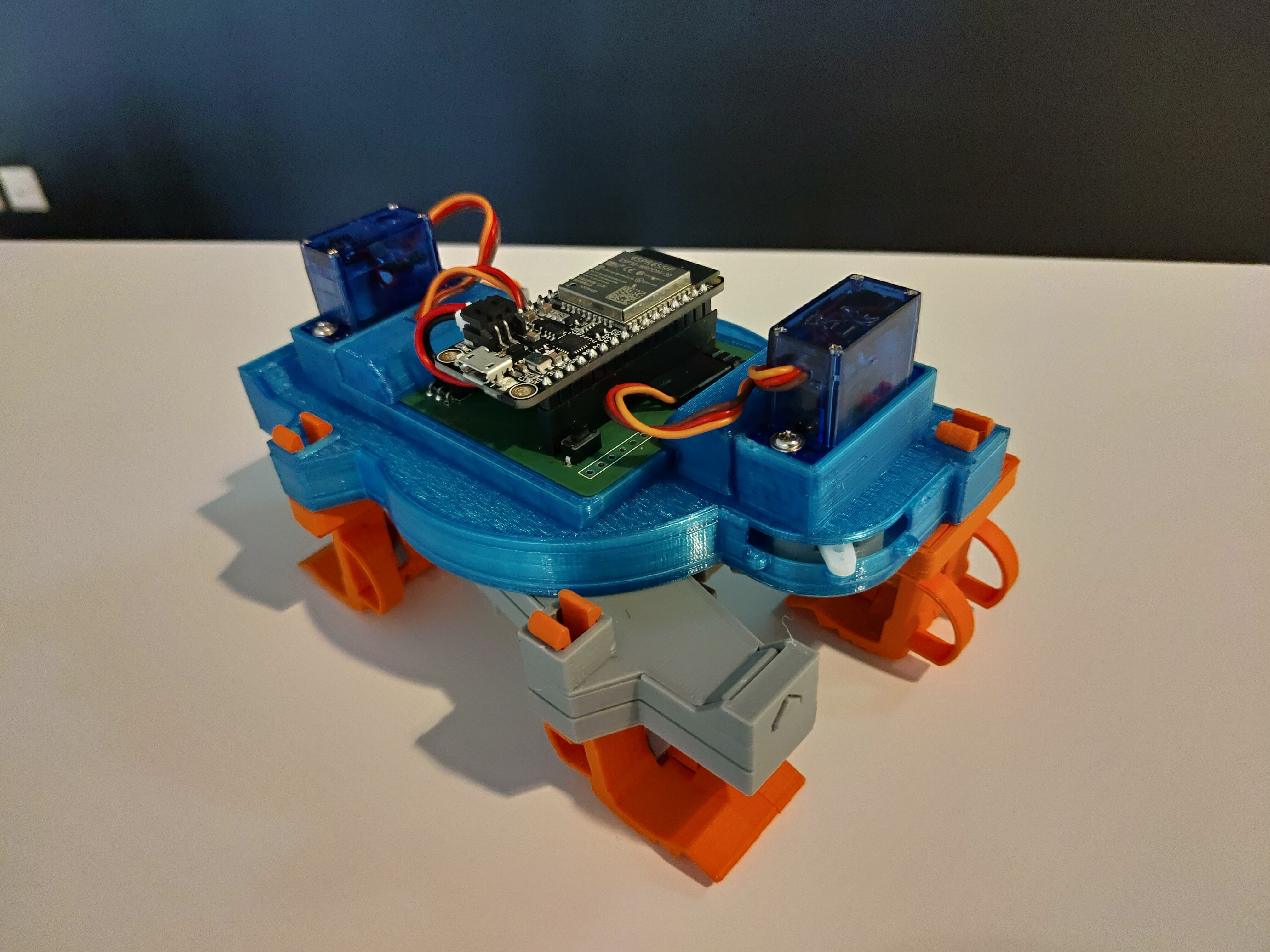
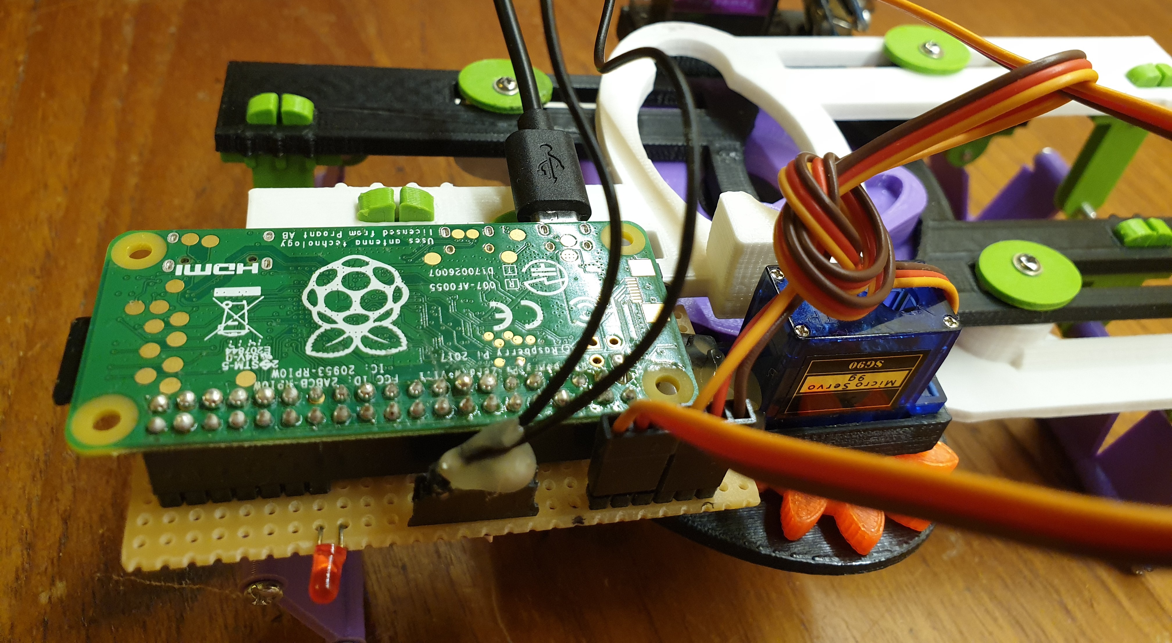
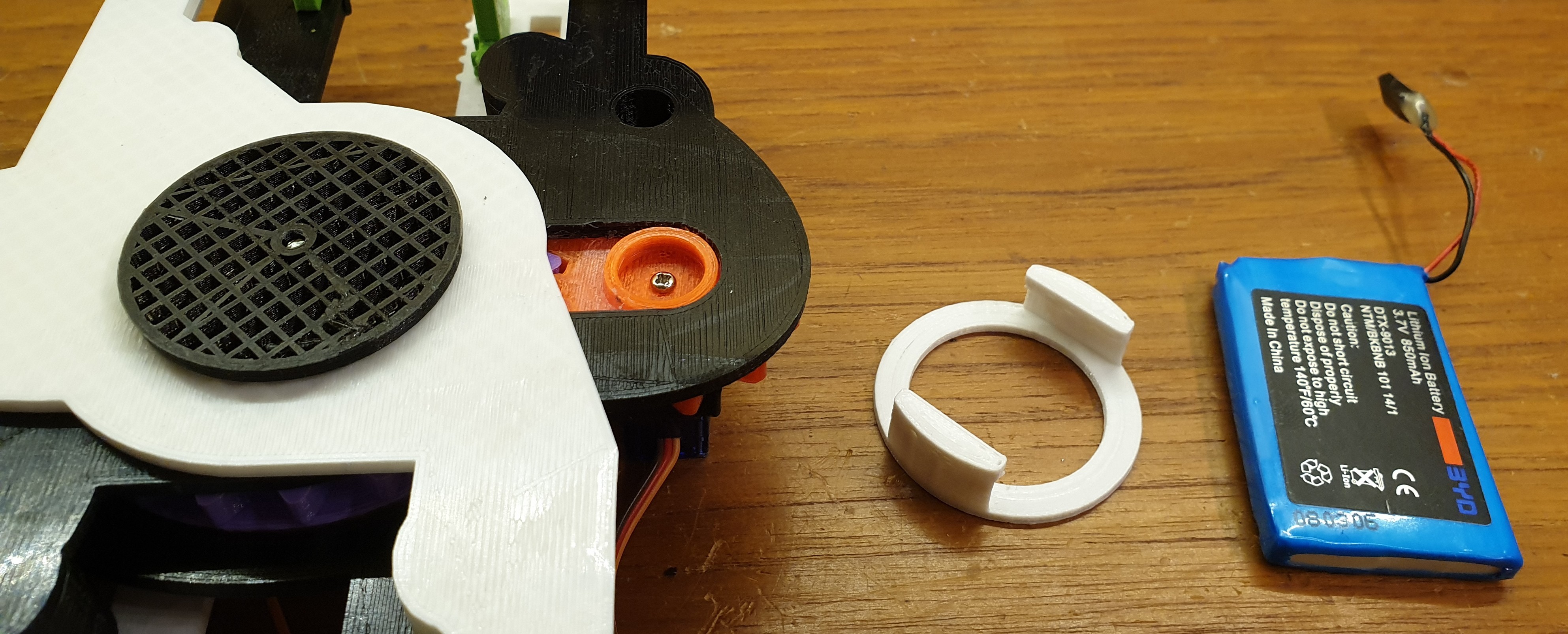
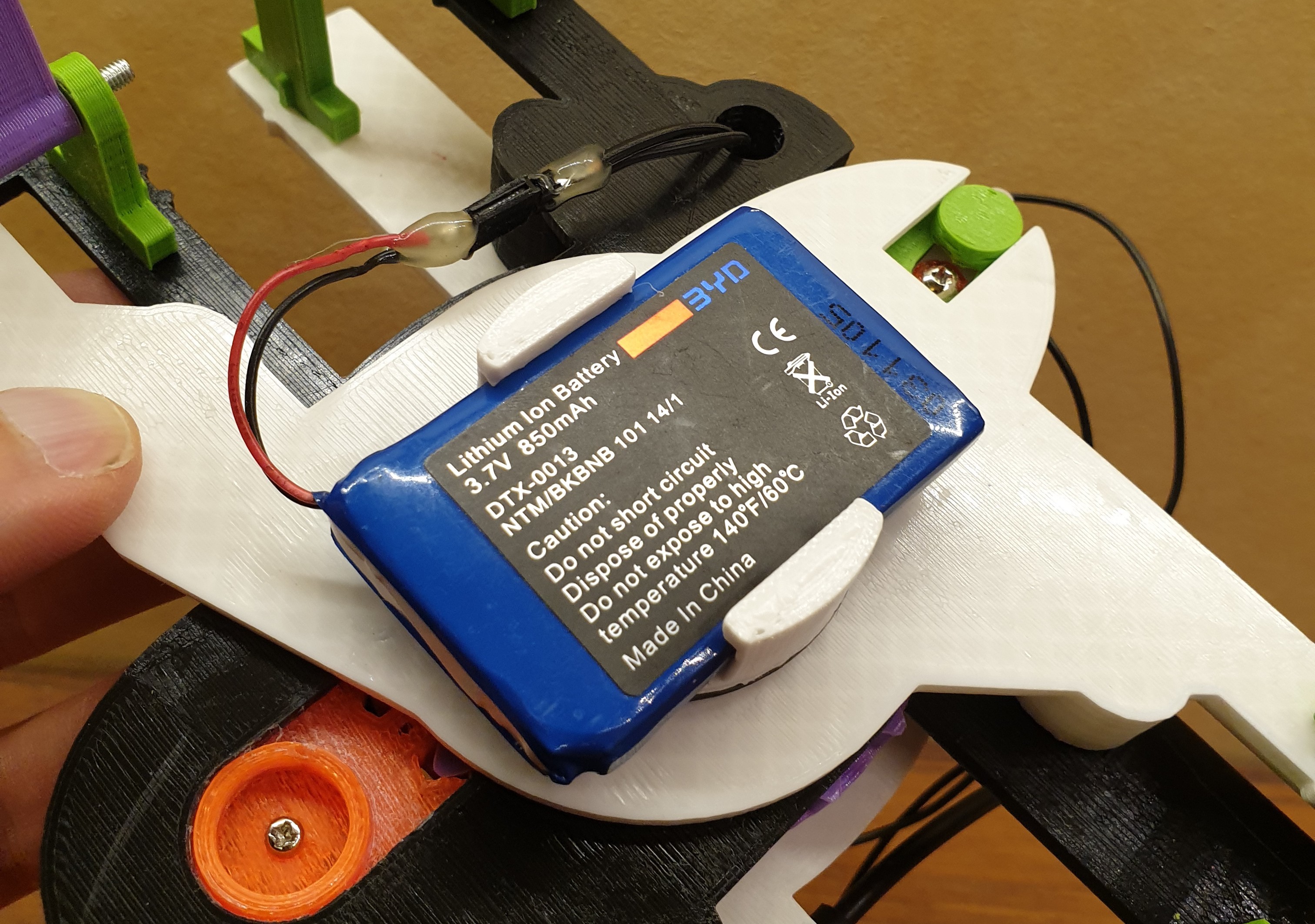
Latest prototype
LB-322: Project close to completion.
Previous prototypes
- LB-312: Iterative improvements. YouTube demo.
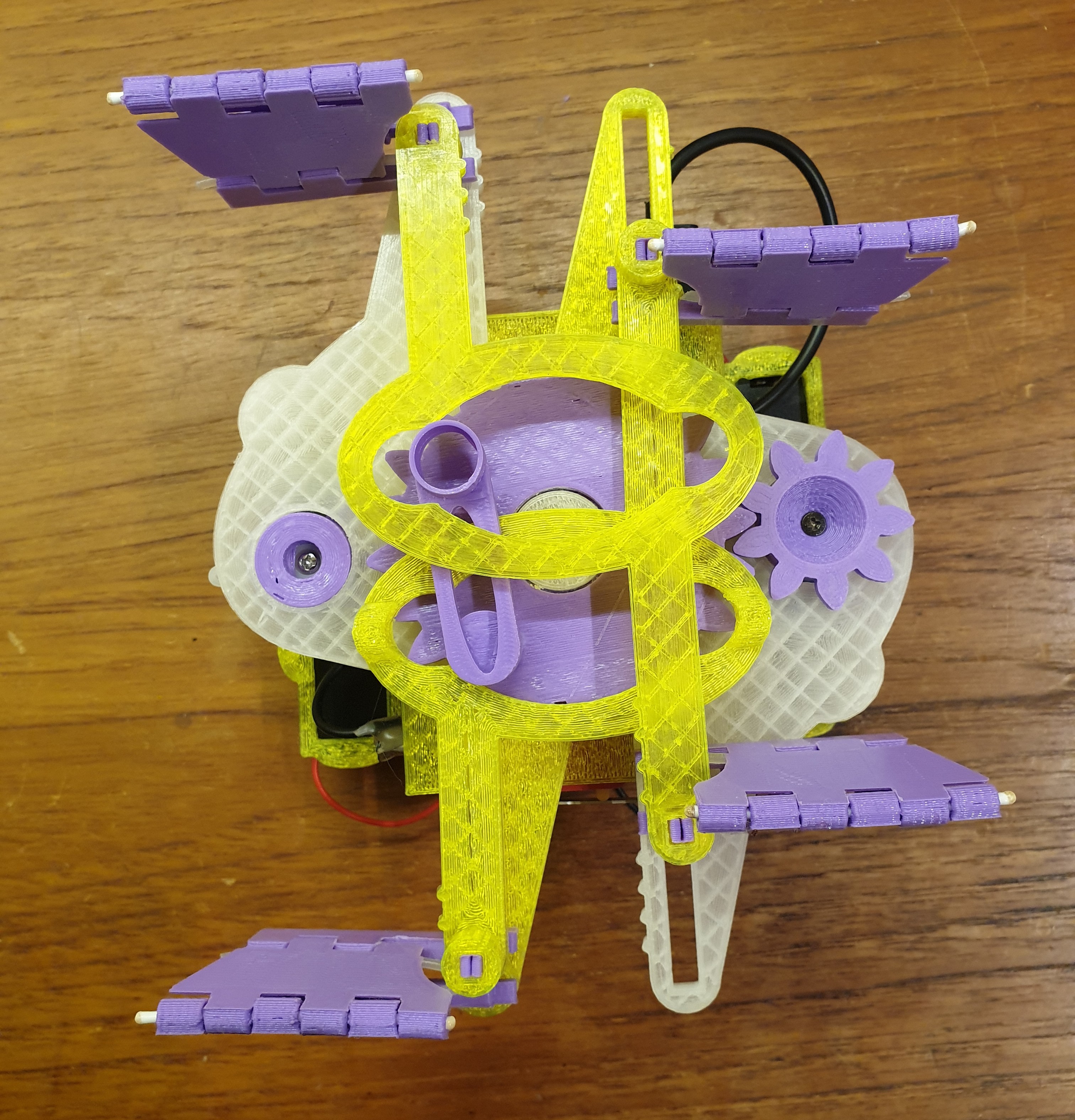
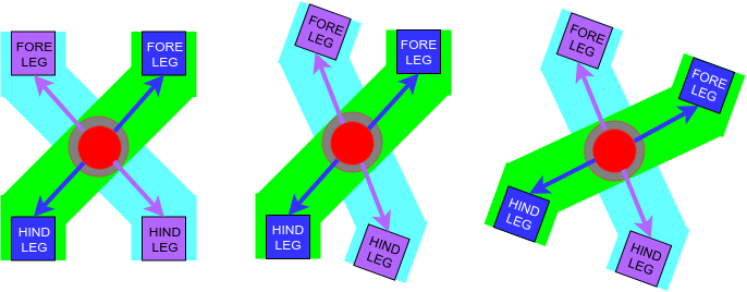
- LB-302: Fully steerable. Uses scissor steering method. YouTube demo.
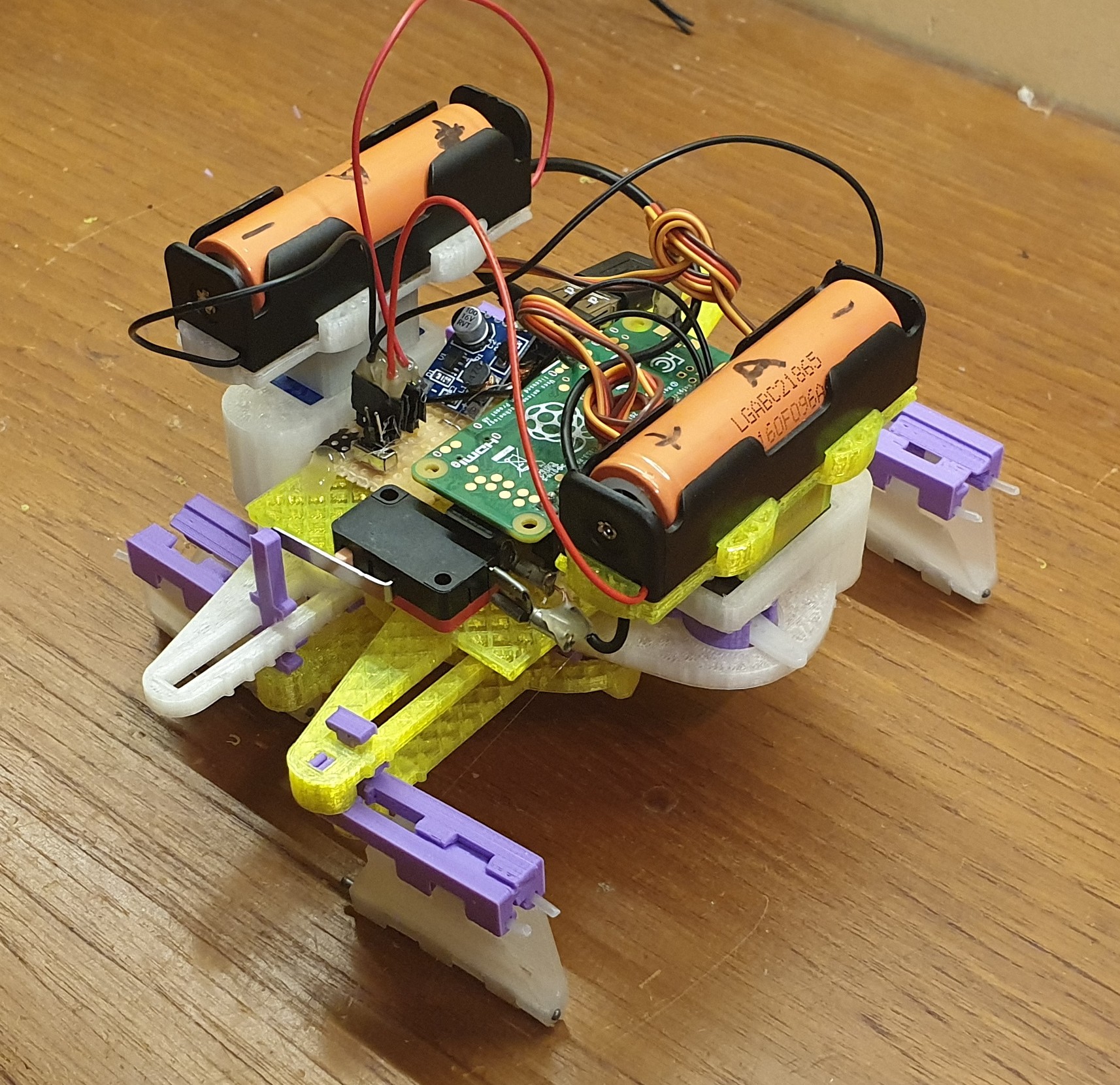
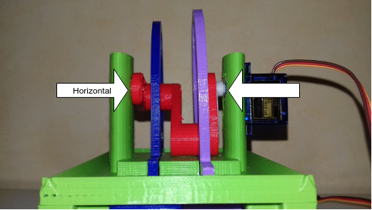
- LB-201: Through the use of a cam and yoke mechanism, only one servo is now required for locomotion. Steering is not implemented on this prototype. YouTube demo.
- LB-101: A modified version of the initial Zero prototype, used for testing articulated steering method. YouTube demo.
- Landbeest Zero: A bare-bones proof of concept for leg movement scheme. YouTube demo.
Naming convention
To distinguish between different prototypes I'm using the naming convention "LB-XYZ", where X, Y, Z are digits 0-9.
- X++ if the drive train has been improved since the last prototype.
- Z++ if steering has been improved.
- Y++ if improvements not related to X and Z have been made.


 Dan DWRobotics
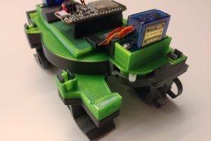
 Martin Vincent Bloedorn
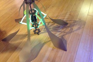
 Sarah Petkus
Wow! Haven't seen anything like this kind of locomotion yet!