I was very encouraged by how well the Landbeest Zero prototype performed. Of course, the glaring weakness of that design is that it can only walk along a straight line.
I'm now about to start cobbling together Landbeest 101 which is supposed to have turning capability. I'm not going to aim for a polished or even fully functional design at this point. With this upcoming prototype I'm only looking to prove to myself that the chosen steering method can get the job done at all.
Articulated steering
The method I've decided on is what I previously called "pivot steering". But after consulting the web I've realized that's something different from what thought it was. I believe the term I'm looking for is articulated steering—the same method used by front loaders.
Zero to 101
With LB-101 I want to keep as much of the old design as I can get away with, in order to get the next prototype up and running as soon as possible. Here's what I'm starting out with:
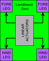
It's a rigid chassis with two linear actuators, which are each coupled with a pair of legs.
To achieve articulated steering I want to split the chassis in a front and a rear carriage, connected by a hinge. The front carriage then houses the forelegs while the rear carriage houses the "engine" and the hindlegs. Ultimately the hinge is supposed to be controlled by a dedicated servo. But with LB-101 I want to keep it simple—I'll just turn it manually for now.
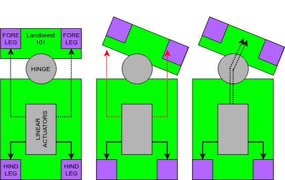
With no motor in the front carriage, there still needs to be some way to transfer motion from the actuators to the forelegs. Since the front carriage needs to turn along the hinge, I obviously can't use a completely rigid structures for that purpose. In the illustration above the dashed arrows indicates that whatever is used to transfer motion to the front carriage needs to be able to flex along with the hinge. Also, the structures transferring motion must not run along the sides of the chassis, since the distance between the actuators and the forelegs changes as the front carriage turns (center figure). Instead they must be aligned with the hinge axis (right figure).
My immediate though was to use bicycle brake cables to transfer linear motion across the hinge. However, since I'd like the Landbeest to remain fully 3d printable (well, save a few M3 screws) I'd prefer not to use it. For the same reason I won't consider using some type of pulley system.
Maybe since my mind was already on bicycles I then thought of a bike chain. Surely there must be a bike chain model somewhere on Thingiverse. A chain is a clunkier solution for sure, but as long as it's path is guided along a channel it should do the job.
Ultimately I ended up with this cable chain instead. It's print-in-place, and since its parametric I can shrink it to a size more suitable for this application.
Quick test of cable chain acting as linear actuator below:
So far so good...
It will probably be a few days until I get the time to chop apart the Landbeest chassis in Tinkercad. I figure it's a 50-50 chance I can actually get this to work, but at least it's worth a shot.
Discussions
Become a Hackaday.io Member
Create an account to leave a comment. Already have an account? Log In.