I've now built and tested the LB-201 prototype, which uses the 1-servo drive mechanism I worked on last week. There's no steering on this one. I'll deal with that issue that later.
Here's LB-201 trying to climb over a few different obstacles:
Too fast
The servo, when at full speed, is really giving the robot a full body workout. That doesn't necessarily translate to better performance though, since the legs tends to loose grip at that speed. I'll probably want to add a reduction gear to future prototypes.
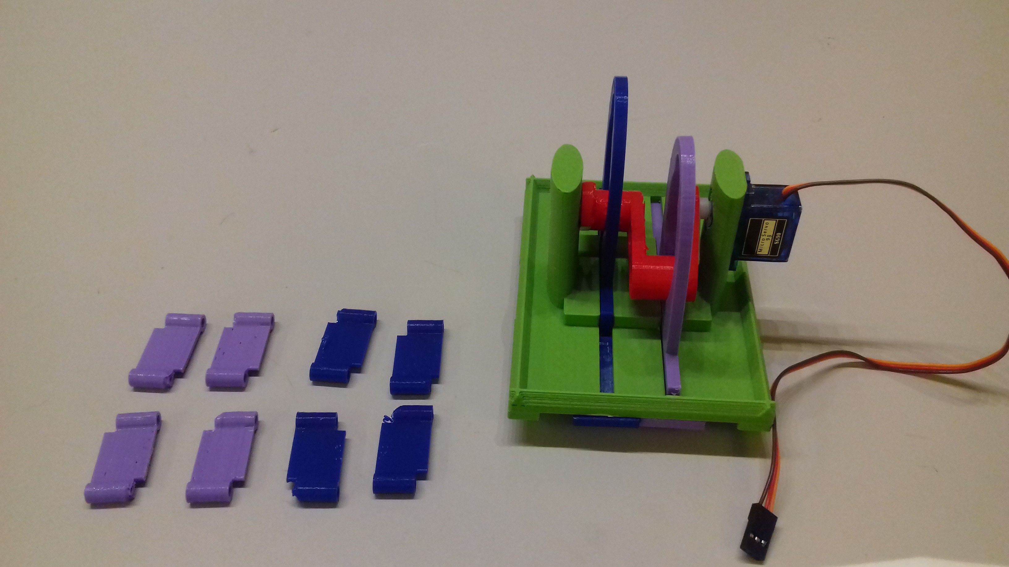
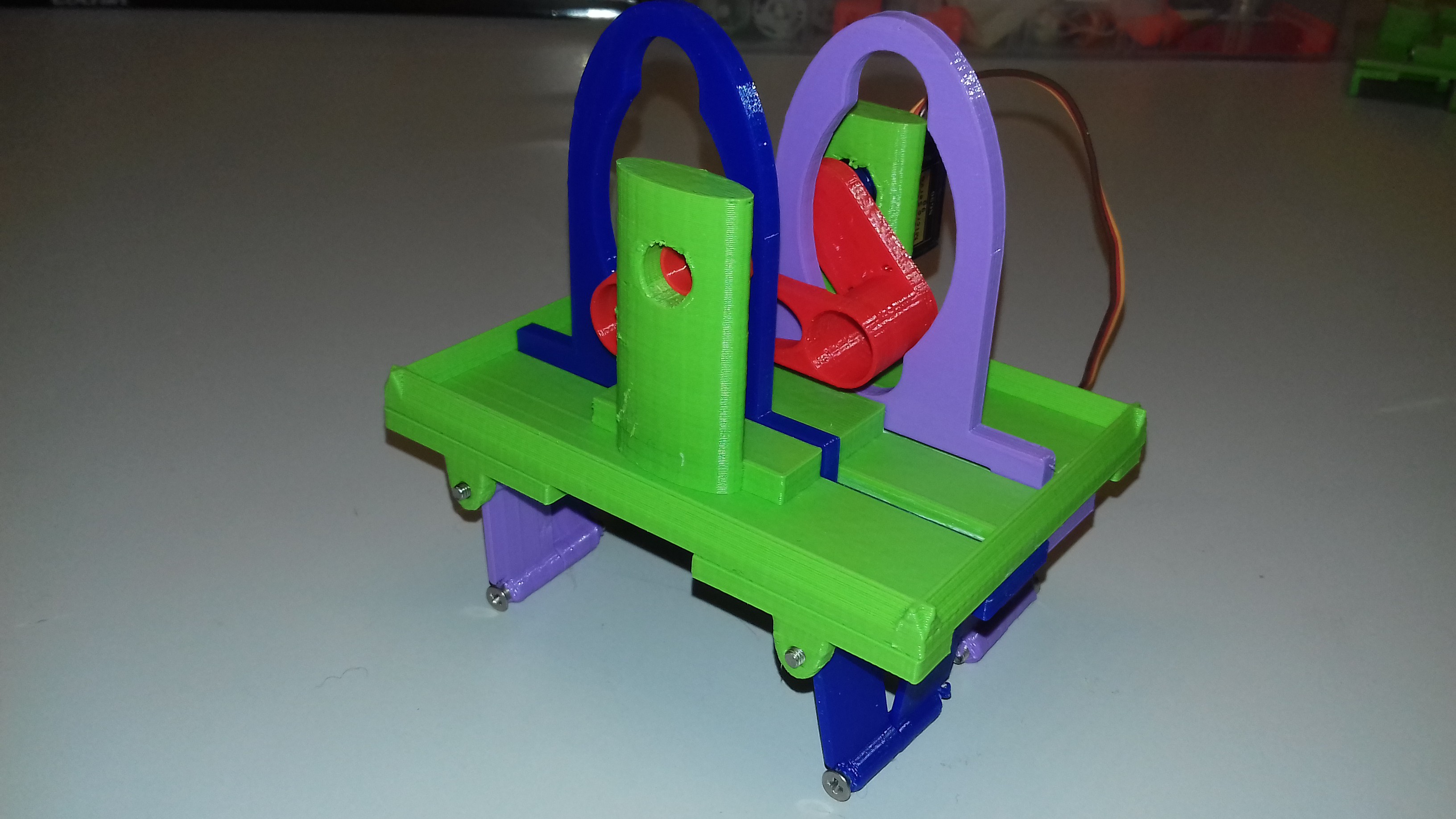
Cam axle orientation
The cam axle is mounted horizontally, which definitely gives this robot something of a steampunk aesthetic. That wasn't something I was striving for though. It just happens to be the simplest arrangement I could think of for coupling the yoke movement to the legs. The obvious flaw with this design is that since the load is off-center it's hard to avoid mechanical friction as the cams moves through the upper range of the yokes.
The perhaps more sensible design choice would be to have the whole assembly turned by 90° so that the side of the yokes are on the same plane as the chassis. In addition to lower risk of friction this would also make the robot less top heavy.
I didn't want to dismiss the horizontal cam axle arrangement without giving it a shot first, since it has the advantage of requiring less intricate 3D printing. But unsurprisingly it proved to have problems with friction which I'm not sure can be remedied merely by refining the design.
Other thoughts
The terrain-going capabilities of LB-201 have been somewhat improved compared to previous prototypes. The linear actuators previously had a travel of 2 cm, which allowed the legs to lift about 1 cm above ground. The cams on LB-201 turns along a 3 cm radius, which also gives the actuators a travel of 3 cm. This means LB-201 can clear obstacles of about 1.5 cm. It's a start, but 2 cm or more would be even better. That's a challenge for another day though.
I'm still using Tinkercad exclusively for this design. But now that the number of moving parts has increased I'm definitely getting to the point where it's a real chore to get all the measurements right. I should probably start thinking about migrating the project to OpenSCAD at some point.
What's next?
I originally planned to have another go at articulated steering as my next project endeavor. But I've recently figured out another method of steering which I think it might have more potential. If I don't find any holes in it I'll lay it all out in my next log post.
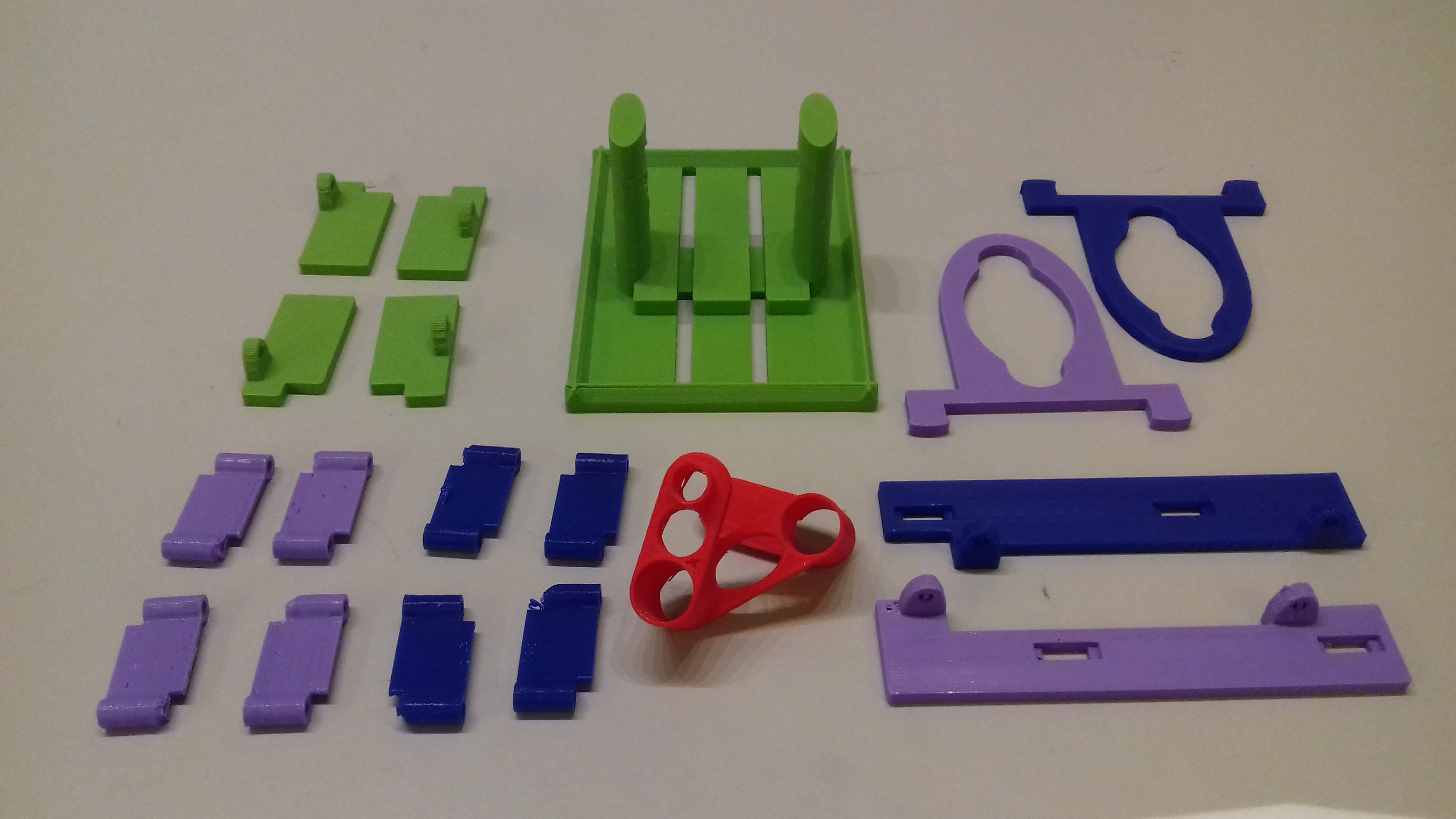
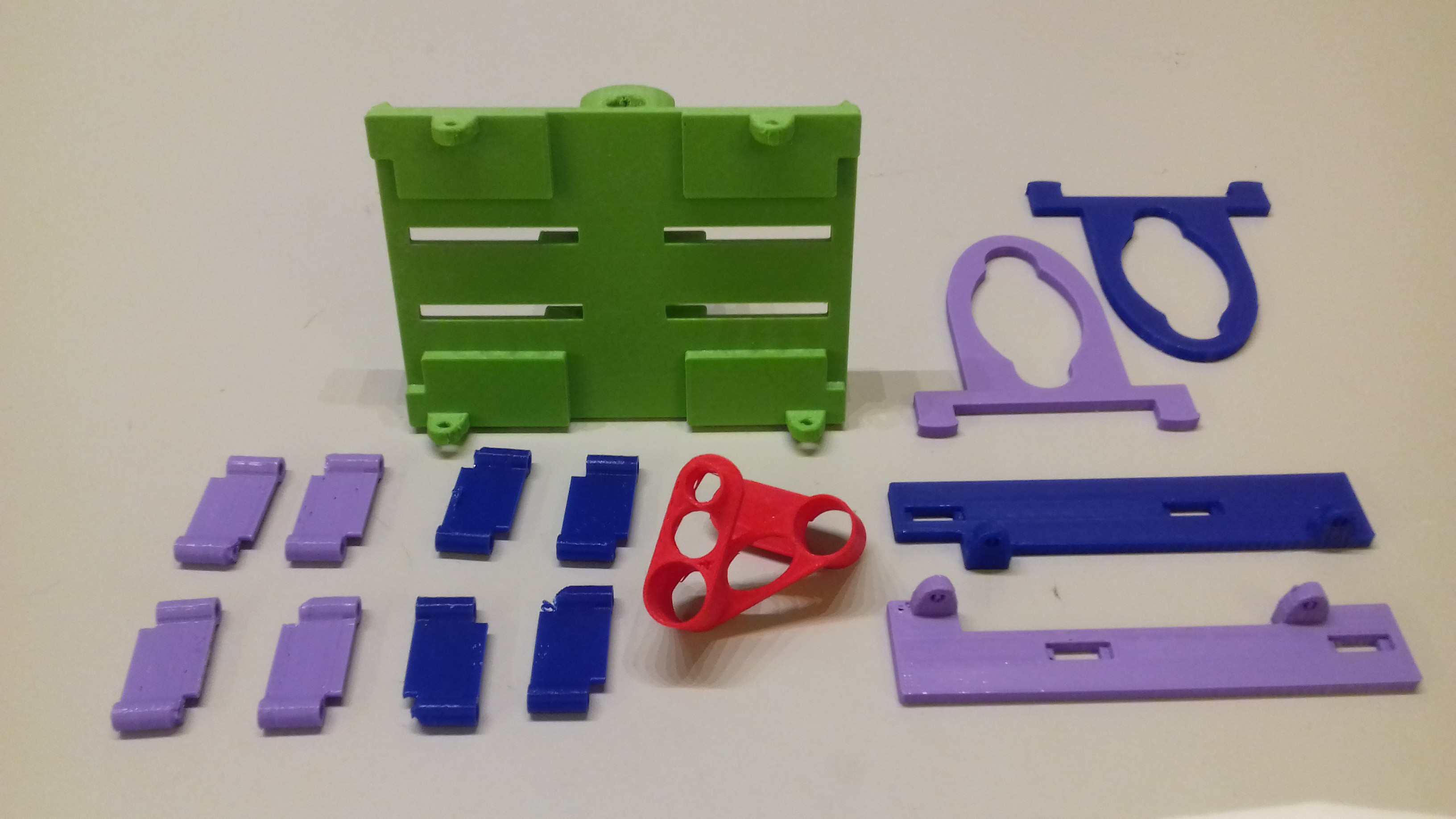
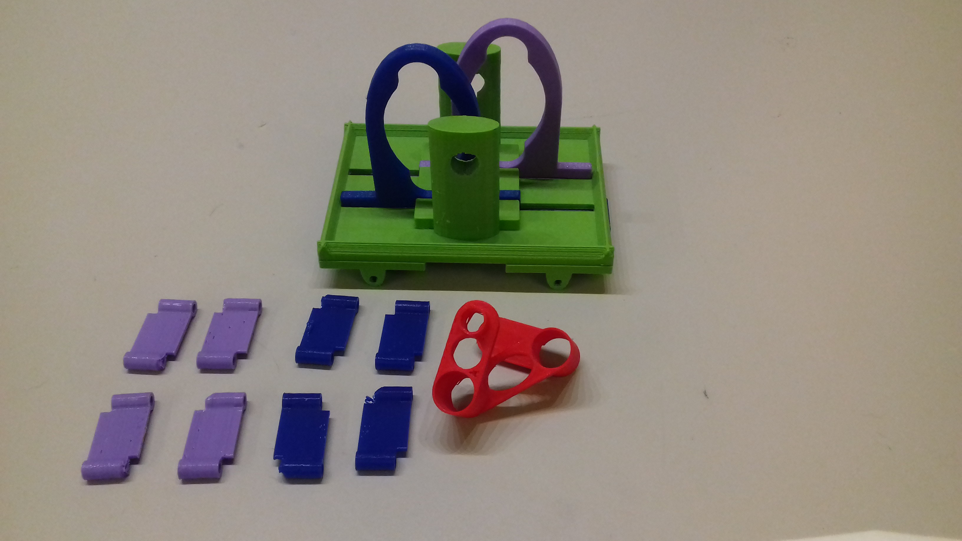
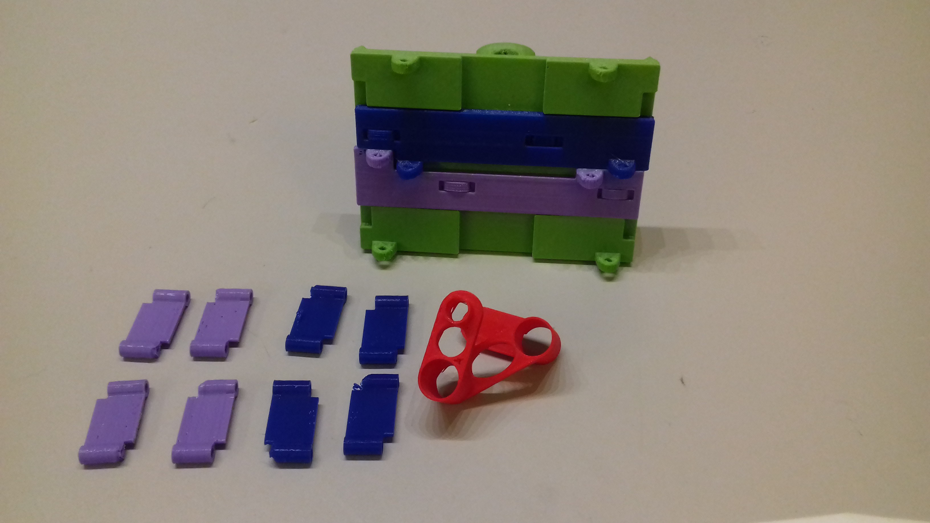
Build
Finally, here are some pictures of the printed parts and how they were assembled:
Discussions
Become a Hackaday.io Member
Create an account to leave a comment. Already have an account? Log In.