-
First steering test deemed tentative sucess
02/05/2019 at 22:33 • 0 commentsI've now built and tested the LB-101 prototype. I spent very little time on this one, and took a lot of design shortcuts.
Mainly I wanted a practical test of turning by means of articulated steering. I also wanted to find out if this steering method is feasible using only 3D printed parts.
I figured that if this very rough draft could manage to turn left and right without immediately breaking down, then there might be some merit to this this type of solution. I'd hate to have spent weeks on a solution that ends up being a dead-end when finally put to the test.
My hopes started waning during assembly and I sort of suspected whole thing would tear itself apart immediately. So I was somewhat surprised it actually worked as well as it did.
Results
Here's LB-101 executing left turns at 15 and then 30 degrees:
The 15° turn performed fairly well, but the robot gets quite unbalanced at 30°. You can also tell the servos are really struggling at 30°. Much steeper than that and they'd stall completely. I took power from an laptop USB output, which I believe maxes out at 500 mA. So given a bit more juice they'd probably have managed to soldier on at a steeper angle. But still there's clearly a lot of friction in the moving parts.
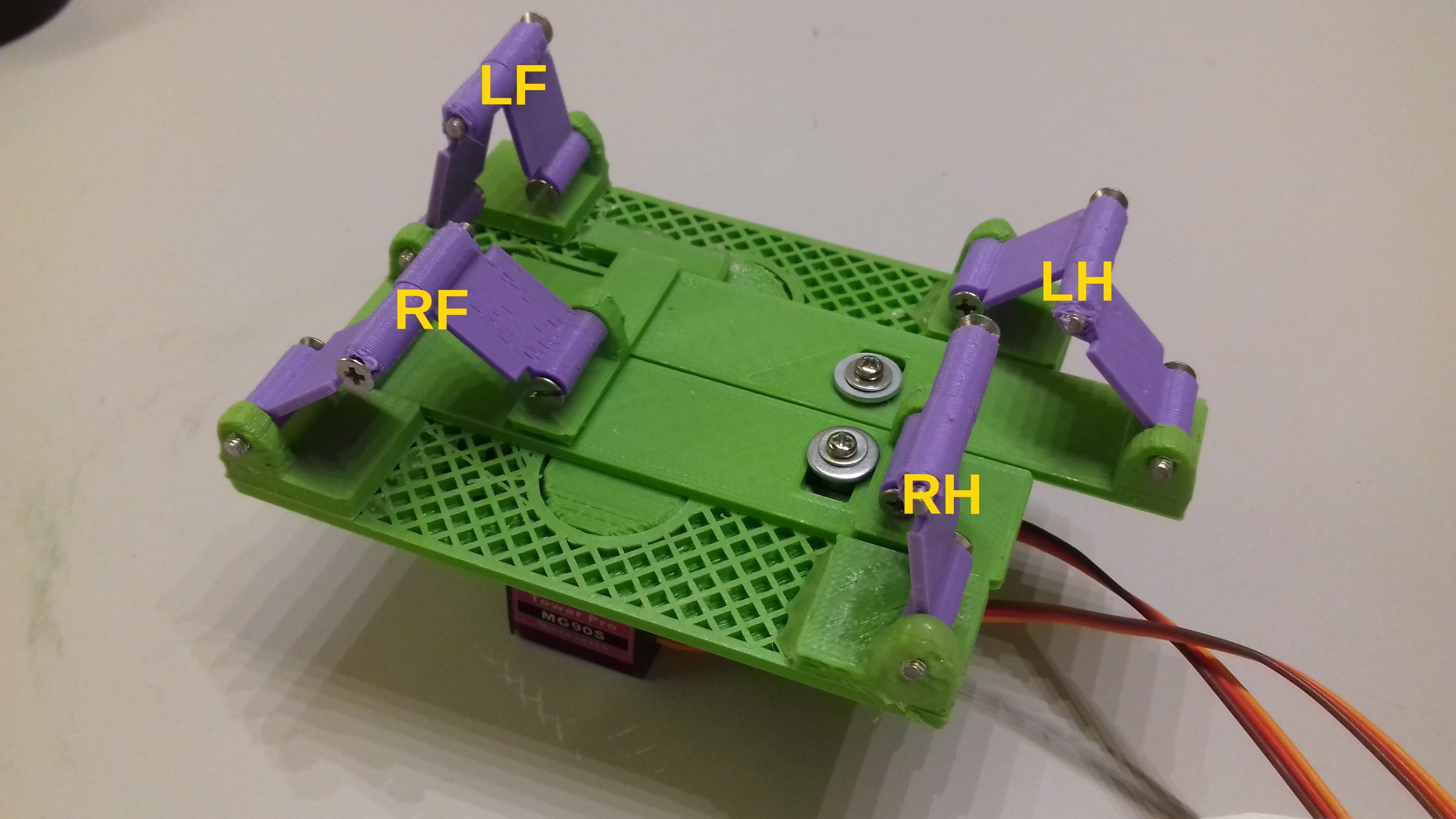
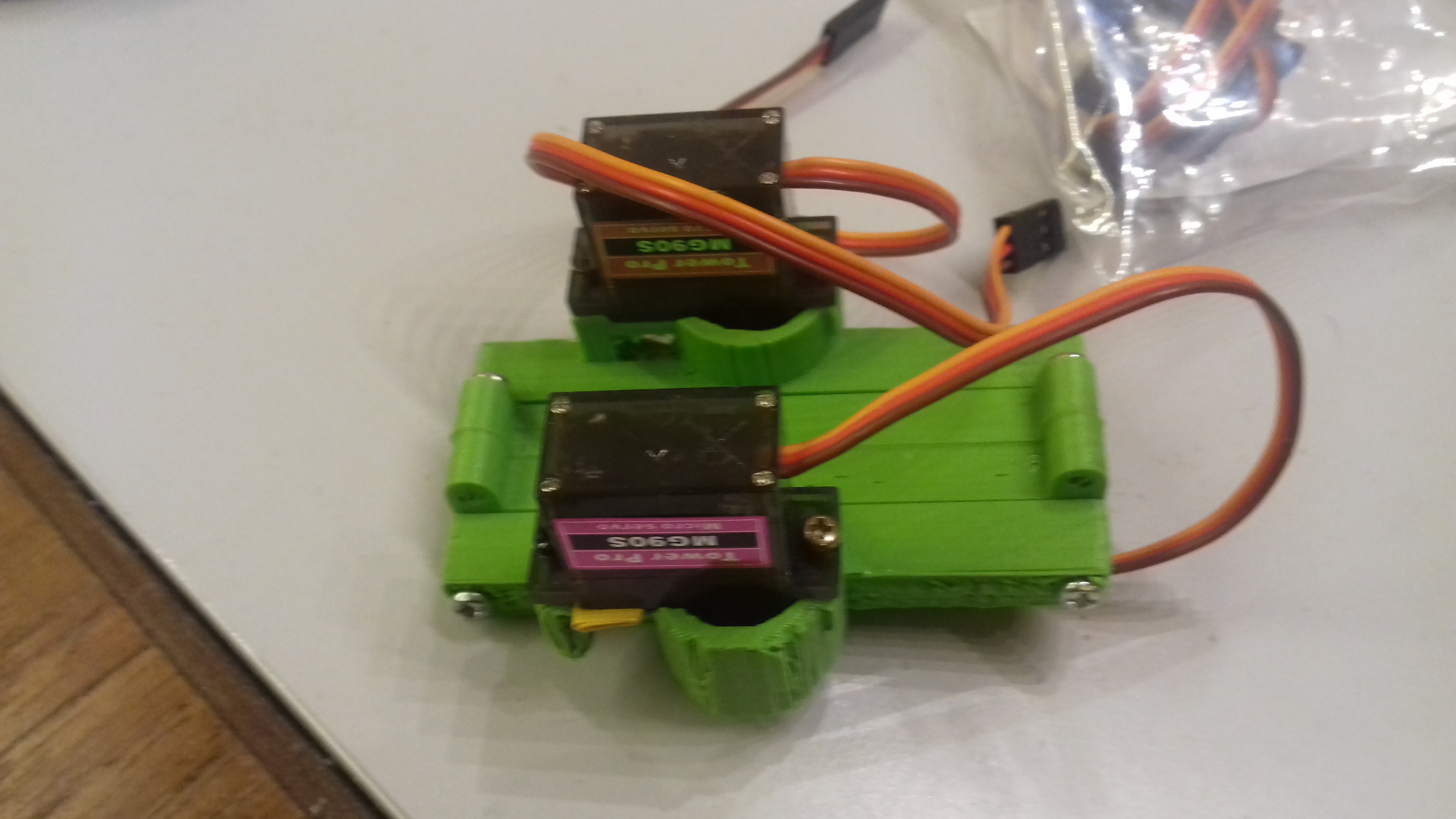
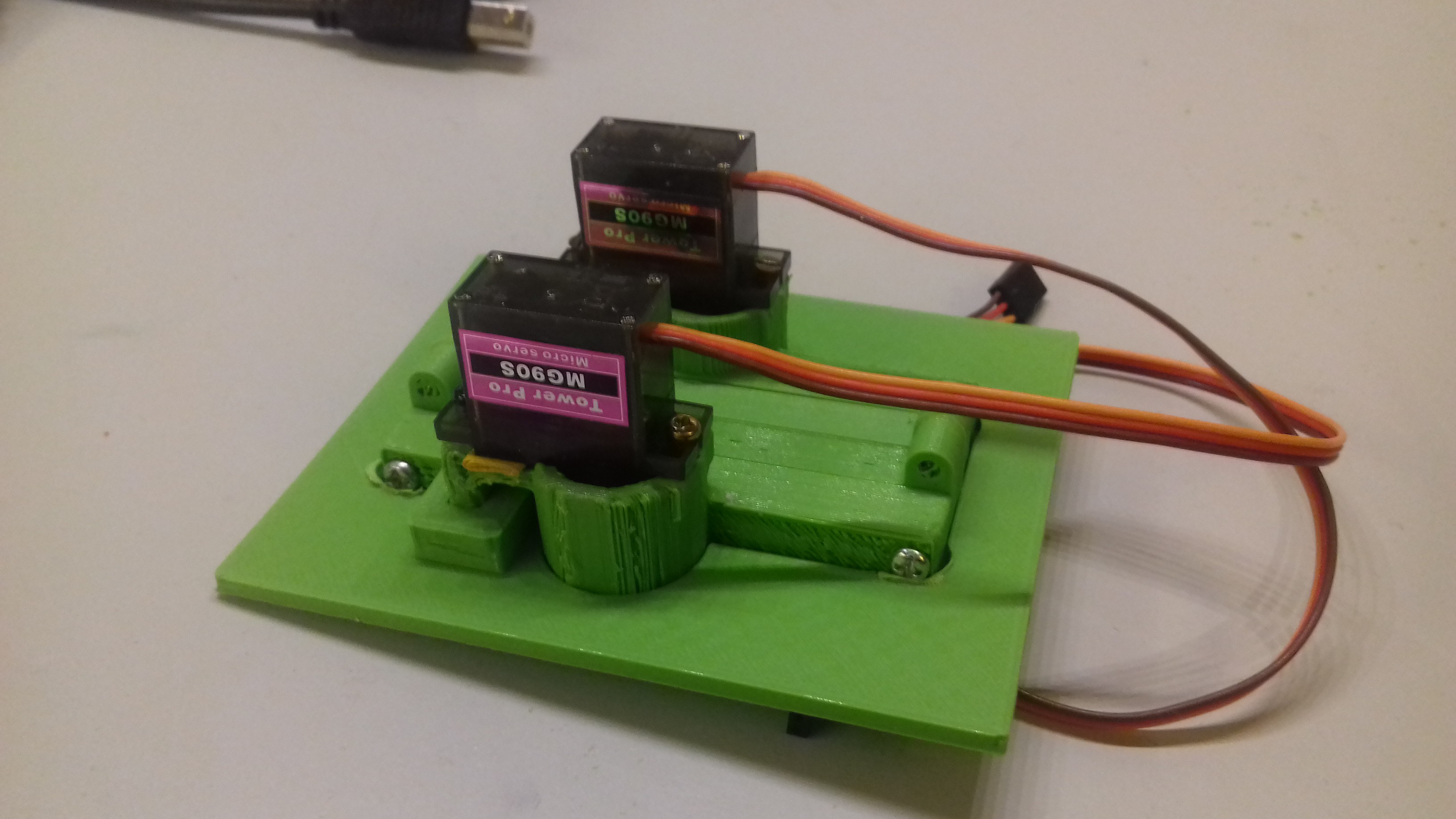
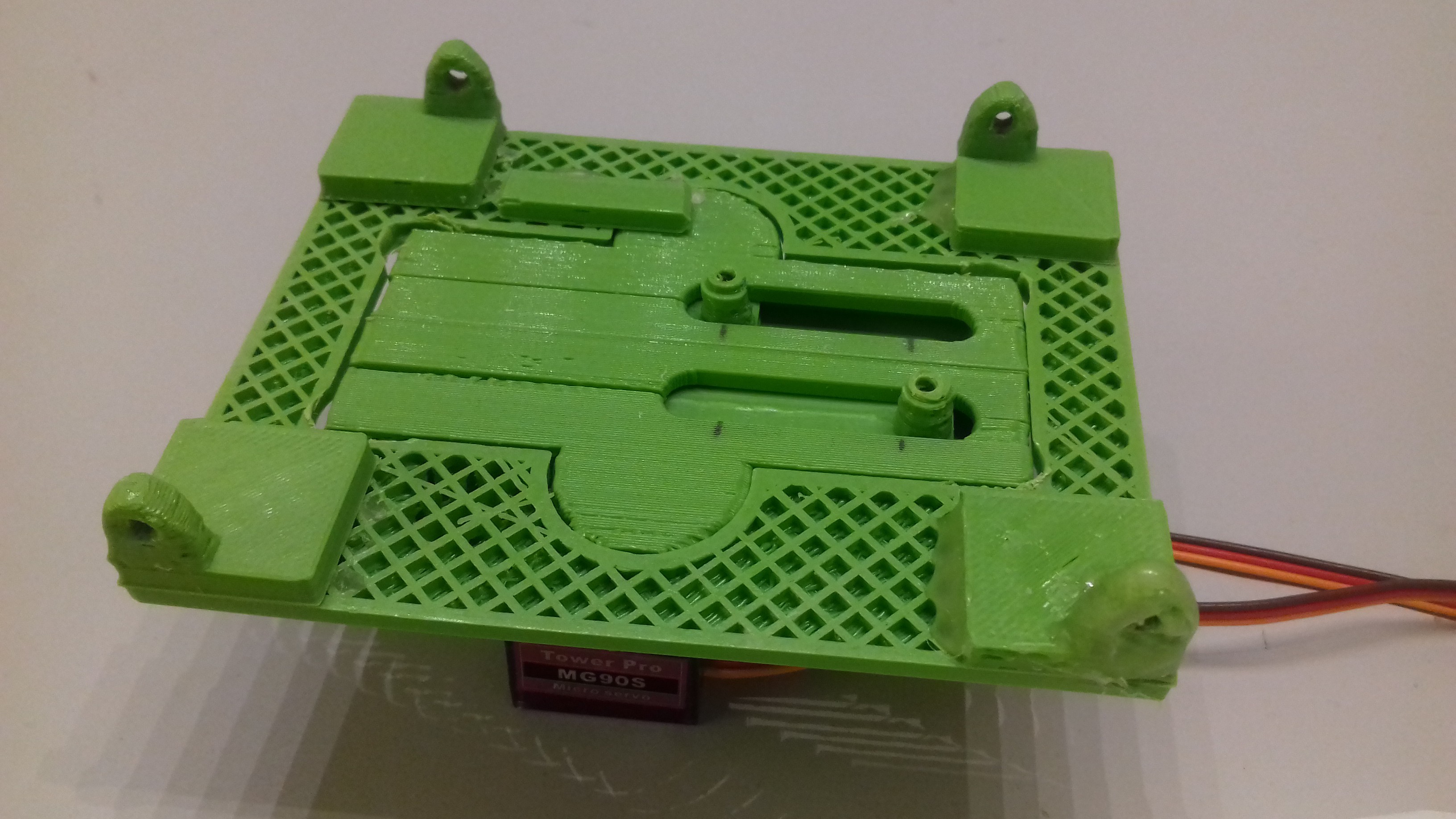
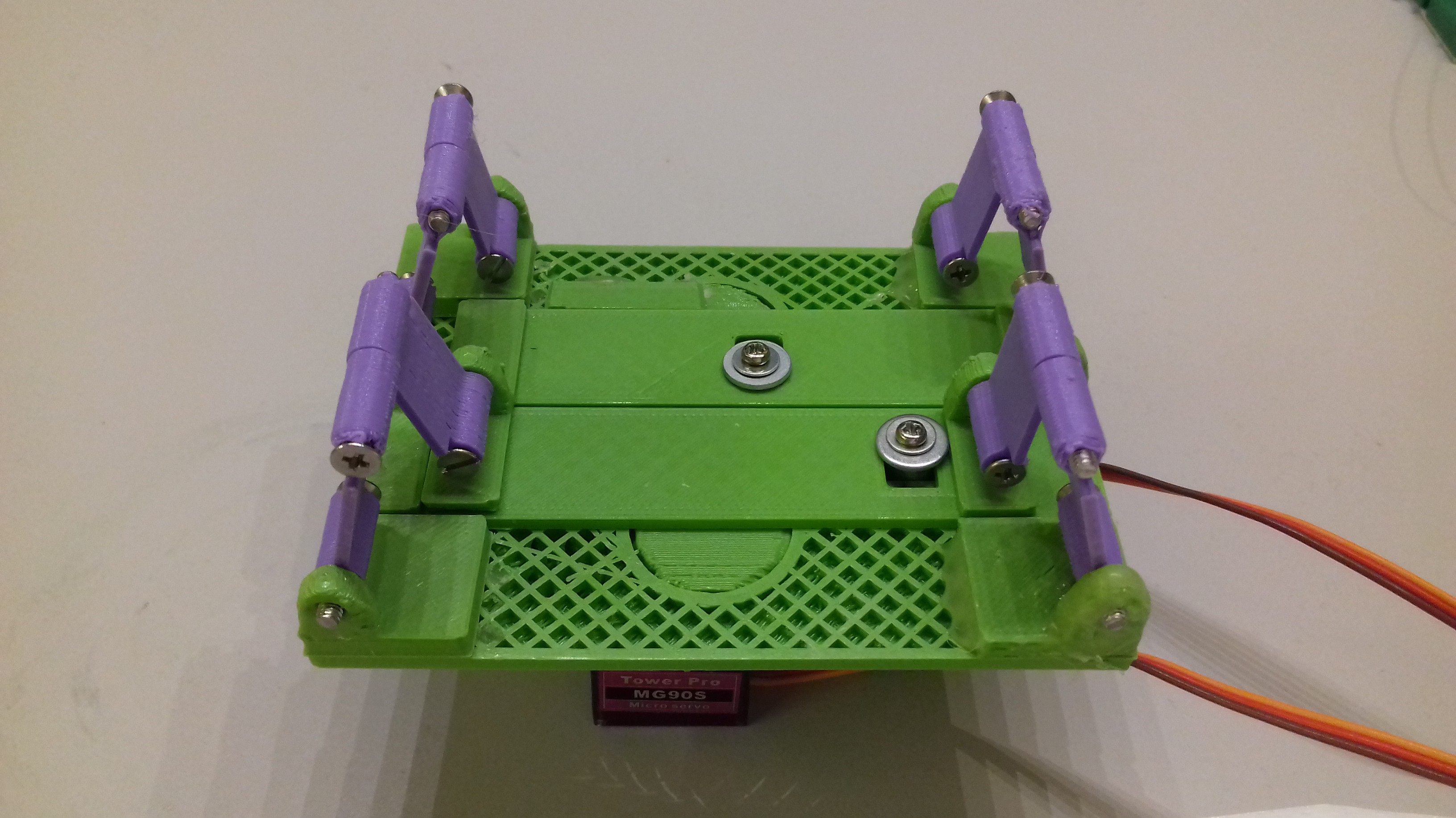
Here's a closer look at the engineering horror story that makes this thing tick:
Compared to the Zero prototype, the two actuators are now about twice as long and have three jointed segments along their travel across the chassis hinge.
On the first run the actuators got misaligned and the whole thing stalled. To keep them moving along the right track I hot glued some bits of plastic under the front carriage. I also put lithium grease on joints and moving parts, but I doubt that makes much of a difference.
Conclusions
Clearly the chassis is too long—left and right legs needs to be spaced further apart. This design error results in the robot leaning over to one side when turning. Since I based LB-101 on the previous prototypes 3D model I just kept the same chassis width of 80 mm while almost doubling the length to 190 mm. Even though I realized this might be a problem, I ignored it in a fit of overzealous shortcut-taking. A reasonable chassis width to length ratio would probably be about 3:4.
Another issue is that the jointed actuators were pretty difficult to print and needed a lot of cleanup before assembly. Some of that is just sloppy design work on my part, but a bit of complexity is just inherent in the concept. I'd prefer that one wouldn't need a perfectly calibrated 3D printer in order to make this thing.
On the whole I'd say articulated steering is a viable method provided I put a lot more work into the design. However I'm still not convinced it's the ideal solution. The turning radius can be improved a bit but it's never going to be tight. And the internal friction will make the robot prone to breaking down after weeks of wear and tear.
The next prototype is going to be all about the new drive train discussed in the previous log. If that works out as well as I hope I will have some more options for controlling the legs movement patterns. Steering by leg movement alone has its own set of challenges but at least it will be more mechanically robust than this method.
In any case I'll put the steering design work on hold for now, and plan to take a fresh look at it in a few weeks. .
-
1-servo drive breakthrough (I think...)
02/04/2019 at 21:25 • 0 commentsAs I've previously mentioned, one of the main project goals is to use only a single servo dedicated to leg movement, rather than the two that are currently required. I've found it difficult to visualize a completely satisfying solution to the problem and I have instead decided to focus mainly on the steering issue for the time being. That priority hasn't changed, but I believe I made a breakthrough today. And since it's now nighttime and I can't sleep I might as well write a log about it.
I'll be rambling on a bit first though, so scroll down to the last paragraph if you just want the solution.
Problem definition
In a previous log I describe the sequence of leg movements Landbeest uses for walking. It consists of a continuous cycle of four poses: A, B, C and D.
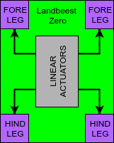
The leg poses are controlled by two linear actuators. Let's call these L and R. They have only two resting states: Max and Min. Below is a diagram that relates the resting states of L and R to each pose.
L R Pose Max Min A Max Max B Min Max C Min Min D In the transition between two poses, an actuator either moves to its opposite state or remains inactive. Only one actuator moves at any transition.
My old crappy solution
There are three major parts to this problem that has made it a little tricky for me to work out a solution:
One part of the problem is how to achieve reciprocating linear motion.
With the current 2-servo design i used servos with 180 degree rotation mounted in this linear sprocket actuator I got off Thingiverse. That's fine as long as there's one servo per actuator, but not if one servo is supposed to move both. For a 1-servo design I'd need to use a continuous 360 degree servo instead. (I'm kind of glossing over how I came to that conclusion, sorry about that.) There's a couple ways of converting rotation to back-and-forth linear motion. I decided on the mechanically simple method used by this device.
The second part is that each actuator should only move half of the time. To do that for a single actuator isn't that hard:
![]()
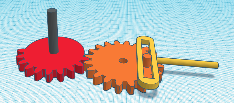
The red gear is connected to the servo and spins continuously in one direction. It's only toothed halfway around so each turn will rotate the orange gear by half, move the yellow actuator to it's opposite extreme position, after which it's stationary for the rest of the red gears turn.
So that's the L actuator taken care of. The third part is where it gets crazy:
![]()
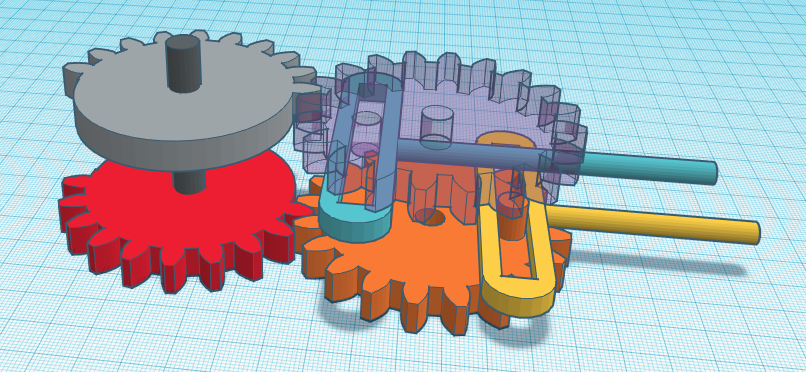
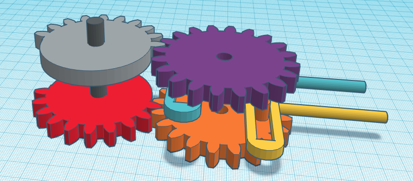
Yeah! So the gray gear is coupled to the same servo shaft as the red gear. It does the same thing for the R actuator (blue) as the red gear does for L, only delayed by one half turn of the servo. It's hard to tell from the picture, but the transparent gear is identical to the orange one only turned upside down. Here's the same image without the transparency:
![]()
While I see no reason why this won't work in theory, there sure are plenty of practical issues with it. Assembling the parts could be quite tricky since each gear must interlock with the right tooth of its neighbor. The assembly must be contained in a housing where the orange gear is mounted to the floor and the purple gear to the ceiling. But the most damning problem is that there's nothing in the mechanism itself that stops the orange and purple wheels from slipping out of alignment while they're not engaged. And I can't think of any worthwhile add-on to remedy that.
The right (?) solution... (Yes I believe it is!)
I finally saw the light today when I was browsing Youtube for some sweet reciprocating piston action and stumbled over this video:
I learned two things from it: First that the wheel and piston assembly I've been using is called a "Scotch yoke". But the major revelation was that you can pause the linear action by introducing a "dwell". That wobbly groove solves all the problems I've been wrestling with in one fell swoop.
I can ditch the half-toothed gears and mount the servo directly to the yoke wheel instead. I can then add a second piston (R) on top of the first one (L), both coupled with the same peg. Only difference is the second piston has its dwell mirrored. That's it in a nutshell.
Finding out about the dwell also brought home how restricted your thought process really is most of the time. Scary. So I guess I learned three things.
I'm sure a mechanical engineer would have solved this problem in a minute, but I must say I'm really satisfied having finally cracked this nut. For me it was a hard one.
Also I'm really sleep deprived at the moment, so I might be overlooking something that will uncrack that nut again. Guess I'll find out tomorrow when my brain starts working again. (Today really—it's 4 am.)
-
LB-101 prototype sketch
02/04/2019 at 12:56 • 0 commentsI was very encouraged by how well the Landbeest Zero prototype performed. Of course, the glaring weakness of that design is that it can only walk along a straight line.
I'm now about to start cobbling together Landbeest 101 which is supposed to have turning capability. I'm not going to aim for a polished or even fully functional design at this point. With this upcoming prototype I'm only looking to prove to myself that the chosen steering method can get the job done at all.
Articulated steering
The method I've decided on is what I previously called "pivot steering". But after consulting the web I've realized that's something different from what thought it was. I believe the term I'm looking for is articulated steering—the same method used by front loaders.
Zero to 101
With LB-101 I want to keep as much of the old design as I can get away with, in order to get the next prototype up and running as soon as possible. Here's what I'm starting out with:
![]()
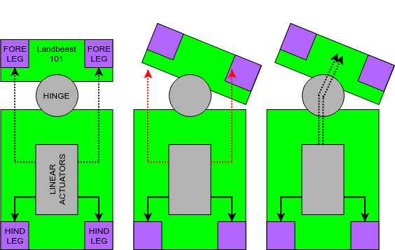
It's a rigid chassis with two linear actuators, which are each coupled with a pair of legs.
To achieve articulated steering I want to split the chassis in a front and a rear carriage, connected by a hinge. The front carriage then houses the forelegs while the rear carriage houses the "engine" and the hindlegs. Ultimately the hinge is supposed to be controlled by a dedicated servo. But with LB-101 I want to keep it simple—I'll just turn it manually for now.
![]()
With no motor in the front carriage, there still needs to be some way to transfer motion from the actuators to the forelegs. Since the front carriage needs to turn along the hinge, I obviously can't use a completely rigid structures for that purpose. In the illustration above the dashed arrows indicates that whatever is used to transfer motion to the front carriage needs to be able to flex along with the hinge. Also, the structures transferring motion must not run along the sides of the chassis, since the distance between the actuators and the forelegs changes as the front carriage turns (center figure). Instead they must be aligned with the hinge axis (right figure).
My immediate though was to use bicycle brake cables to transfer linear motion across the hinge. However, since I'd like the Landbeest to remain fully 3d printable (well, save a few M3 screws) I'd prefer not to use it. For the same reason I won't consider using some type of pulley system.
Maybe since my mind was already on bicycles I then thought of a bike chain. Surely there must be a bike chain model somewhere on Thingiverse. A chain is a clunkier solution for sure, but as long as it's path is guided along a channel it should do the job.
Ultimately I ended up with this cable chain instead. It's print-in-place, and since its parametric I can shrink it to a size more suitable for this application.
Quick test of cable chain acting as linear actuator below:
So far so good...
It will probably be a few days until I get the time to chop apart the Landbeest chassis in Tinkercad. I figure it's a 50-50 chance I can actually get this to work, but at least it's worth a shot.
-
Decision tree for next prototype
02/01/2019 at 20:57 • 0 commentsI feel that the Zero prototype worked surprisingly well considering how little preparation had gone into it. That being said, it's useless as anything but a cute toy.
I'm not setting the bar very high for considering this project a sucess though. I just want it to be useful as a simple Arduino or RPi robot platform, and to be easy to build using servos, 3d printed parts and m3 screws.
Really, the main thing missing for project success, is directional steering. Landbeest doesn't need to be fast or nimble or able to turn on a dime. But it must be able to get to where it's going eventually.
The second requirement is simplicity. The Zero prototype fits that requirement just fine. But a steerable Landbeest will inevitably be a bit more complex. Complexity arises from two main factors: the number of sevos, and the number of mechanical parts. In many cases by using more servos, the mechanical complexity can be decreased, and vice versa.
I've dreamed up a number of ways to proceed with the project but now is the time to stop procrastinating. In this log I'll build a little decision tree to justify to myself that I'll be doing the "right thing wrong", rather than the "wrong thing right".
How to implement steering
I really like the leg mechanics of the Zero prototype for it's simplicity. Only one tiny drawback: there's no possible sequence of servo action that will make it turn left or right. This basically has to do with the fact that opposing fore- and hindlegs are mechanically coupled and moves in lockstep.
One solution would be to ditch the current movement scheme and just resort to control each leg with a dedicated servo.
I'd still be using the same hinged triangular legs, only now they'd be mounted symmetrically and controlled independently. Thus the "feet" are still restricted to a simple pendulum motion in one plane only. As far as I can visualize it, turning would be possible but cumbersome. You'd be able to pivot incrementally by keeping two diagonal legs raised while swinging the other pair in opposite directions (then do a little leg sequence to reset and keep pivoting). This would only work effectively if legs where spaced apart to certain dimensions though. And while I'm sure turning while moving forward is possible I can only see it being an ugly and tedious grind.
Another solution would be tank control —the same way two-wheel drive robots do it. This essentially means I would mount two identical Landbeest modules side by side in conjoined twin mode.
Boom! Double the complexity: eight legs, four servos —ridiculous! And turning would be as graceful as with a WW2 tank. Nope. No way I'm doing that.
Third solution. Do you ever ask yourself: how would a cat with four peglegs execute a turn?
You don't? Well, I think it would do it by just bending its waist a bit while walking. So if I introduce a pivot point somewhere on Landbeests chassis it should be able to turn at least as well as a quadruple amputee cat. (Like I said, this project is all about setting attainable goals.)
I'm instantly attracted by this solution. If you can control the "waist" pivot, the gait won't have to change in order to do a turn. Thus I could essentially keep the current drivetrain as is. The only challenge is how to transfer linear motion across the pivot point.
I'm going with the pivoting waist on this one. It could be that I'm glossing over the "dedicated servo" method and that it has more merit than I realize. But I feel that the current drivetrain and leg movement scheme is sort of the USP of this project, so I don't want to throw it to the wayside unless I have a really good reason for doing so.
Dos servos por favor
The current prototype uses two servos. The next prototype will need another one to turn the waist pivot. That makes three. That's not really unreasonable for a walker —at least if you compare with some of those spider bots that seem to use a hundred.
But still the dual drive servo setup has bothered me from project day one. I guess mostly because of intellectual vanity. It just seems like a waste since only one servo is used at any given time while walking. Though dual servos are essential for doing this little dance number:
I believe I've figured out a fairly simple solution for a one-servo drivetrain. I won't pitch it at this point, but it mainly involves two geared crank wheels with pistons. That stuff will require a bunch of space though, so it might be a challenge to make it reasonably compact. And surely a bunch of unforseen issues will arise on top of that.
I should add that I've never actually tried my hand at designing gears up until now. (As mentioned in a previous post, I borrowed the currently used linear actuator from Thingiverse.)
The prudent thing to do is to put off the one-servo drive notion to the future and stay with a tried and true solution for the time being. That way I can focus on getting the steering to work for the upcoming prototype.
This whole discussion has led me to make two whole decisions. I think I'll leave it at that with this post:
![]()
-
Leg movement walk-through
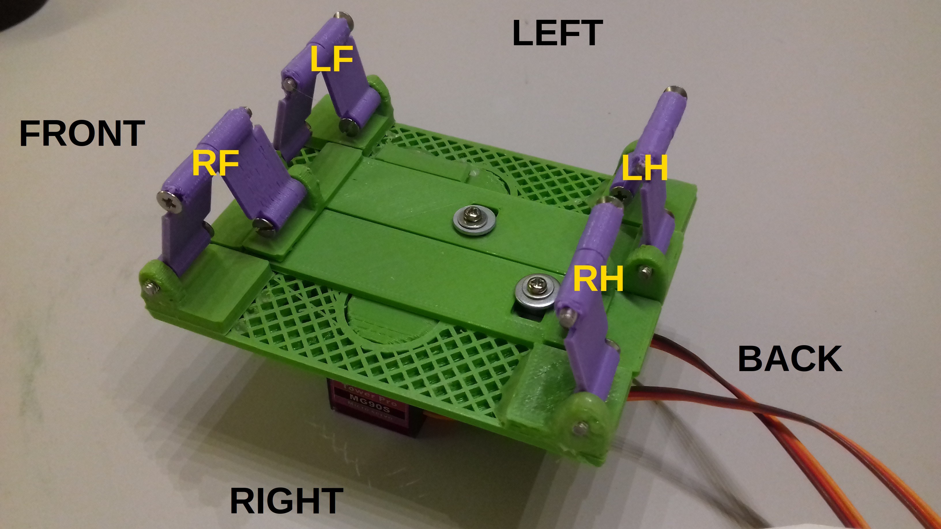
01/31/2019 at 20:09 • 0 commentsBefore writing this post I skimmed the Wikipedia article on animal gaits. From what I can gather, Landbeest basically uses a "walking trot" gait.
Same as in that article, I'm using the following names for the left and right hind- and forelimbs: LH, LF, RH and RF. Of course with Landbeest what's front and back is a bit arbitrary.
When walking, Landbeest cycles between four stationary poses: A, B, C and D. Lets look at them in order.
Pose A
All legs are straight and in contact with the ground.
![]()
Pose B
From pose A, the right actuator moves forward. This flattens LF and RH. Landbeest remains stationary. Only RF and RH now has ground contact. (Since it can be a bit hard to tell which parts are connected on a static image, you might want to have a look at this video too.)
![]()
Pose C
From pose B, the left actuator moves backward. This makes Landbeest move forward as RF and LH flattens. All legs are now flat and in contact with the ground.
![]()
Pose D
From C, the right actuator moves backward. Landbeest moves forward as LF and RH straightens. Now only LF and RH has ground contact.
![]()
Next cycle
The next cycle begins when transitioning to pose A again. Rinse and repeat to keep Landbeest moving forward.
It should be noted that actual forward motion only happens on transition B to C and C to D.
To reverse Landbeests walking direction, simply reverse the cycle of poses to D, C, B, A.
Asymmetric leg mechanics
There's a certain asymmetry in how the legs are mounted and how they move. Each leg acts as a hinge (and forms a triangle) between a fixed point on the chassis and a sliding point. The fixed point is different on the left and right side though. And the right and left side legs also straightens and flattens in opposite directions to their "twins".
I find it remarkably difficult to explain in words why this is a better idea than using a symmetric layout. I have to give up for now, but I might get back to it in a later post. Anyhow, readers can probably figure it out easier on their own than trying to make sense of my word-soup. Basically it just allows for a very simple driving mechanism, where each leg still gets to clear a certain distance above obstacles on the ground.
-
First prototype build
01/31/2019 at 04:04 • 0 commentsI want to start the project with immediately building a working prototype, even though I havn't got all the details worked out yet. I'm calling it "Landbeest Zero".
The main thing I want to try out with Zero is leg movement for simple locomotion along a straight line. I'm not worrying too much about the intricacies of the drivetrain at this point, as long as the legs move like they're supposed to. And I'm not above stealing parts of the design if it means getting the prototype done quicker.
The main thing I want to "steal" is a linear actuator to use with the two servo motors. After a little browsing I found this design by [fastmike75] on Thingiverse. It's compact, rugged and easy to print —just what I need.
![]()
![]()
I imported the linear actuator model into Tinkercad and designed the rest of the prototype around it. I probably should learn how to use a real CAD suite at some point, but Tinkercad is pretty much perfect for small tasks like this.
When modelling mechanical parts for 3d printing I prefer to print a very flimsy first draft since I usually have to change something and print it over again anyway. But this time most parts came out serviceable enough on first try —hence the exposed infill here and there.
![]()
![]()
Next I attach the hinge parts that connects one side of each leg directly to the chassis. Note how they aren't symmetrically placed on each corner. (I'll go into why in a later post.)
![]()
And no, I didn't sneeze on the lower-right hinge. It broke and I had to fix it with hot glue.
Finally there's the two slidy things, which connects two legs to each linear actuator:
![]()
Landbeest Zero is a mess of hot glued ill-fitting parts and it barely holds together. But it works dammit, and I feel very encouraged to start on round two of this project.
Landbeest walking robot
Terrain-going quadruped. 3D printable. Two servo drive.