 Just4Fun
* * HARDWARE OVERVIEW * *
The Thing is the the "natural" evolution of the CPLD Fun Board. The idea was to make a FPGA board using cheap and easy to find components, with a STM32 Arduino used as "stimulus generator" or "companion" processor for the FPGA, and with a 512KB SRAM and common I/O as GPIOs, VGA and a PS/2 keyboard to "run" HDL SOCs.
More, it has the option to "run" easily Multicomp VHDL SOCs having the needed HW.
Multicomp is a modular VHDL design to "run" some famous retro 8 bit CPUs made by Grant Searle and described here.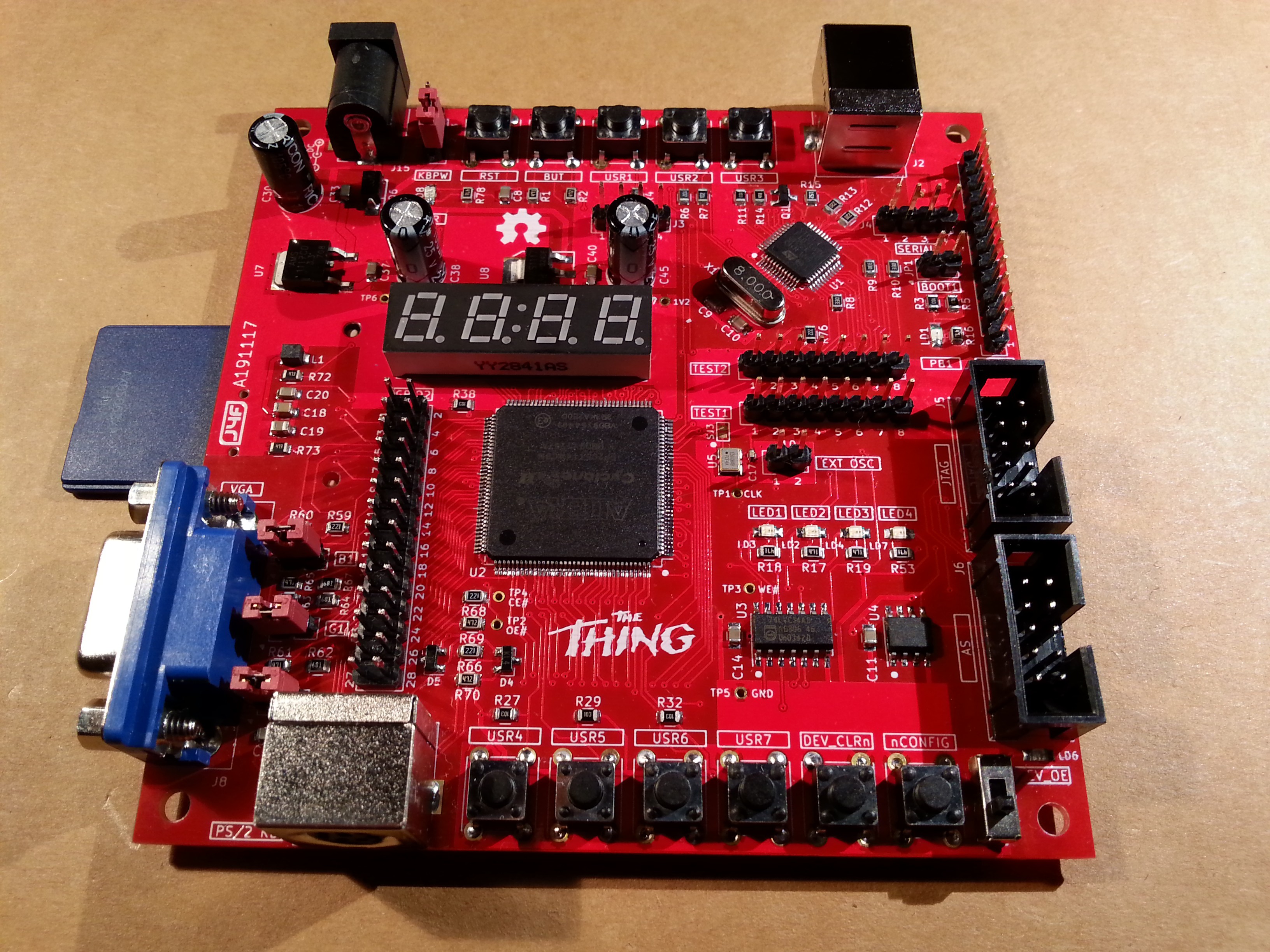
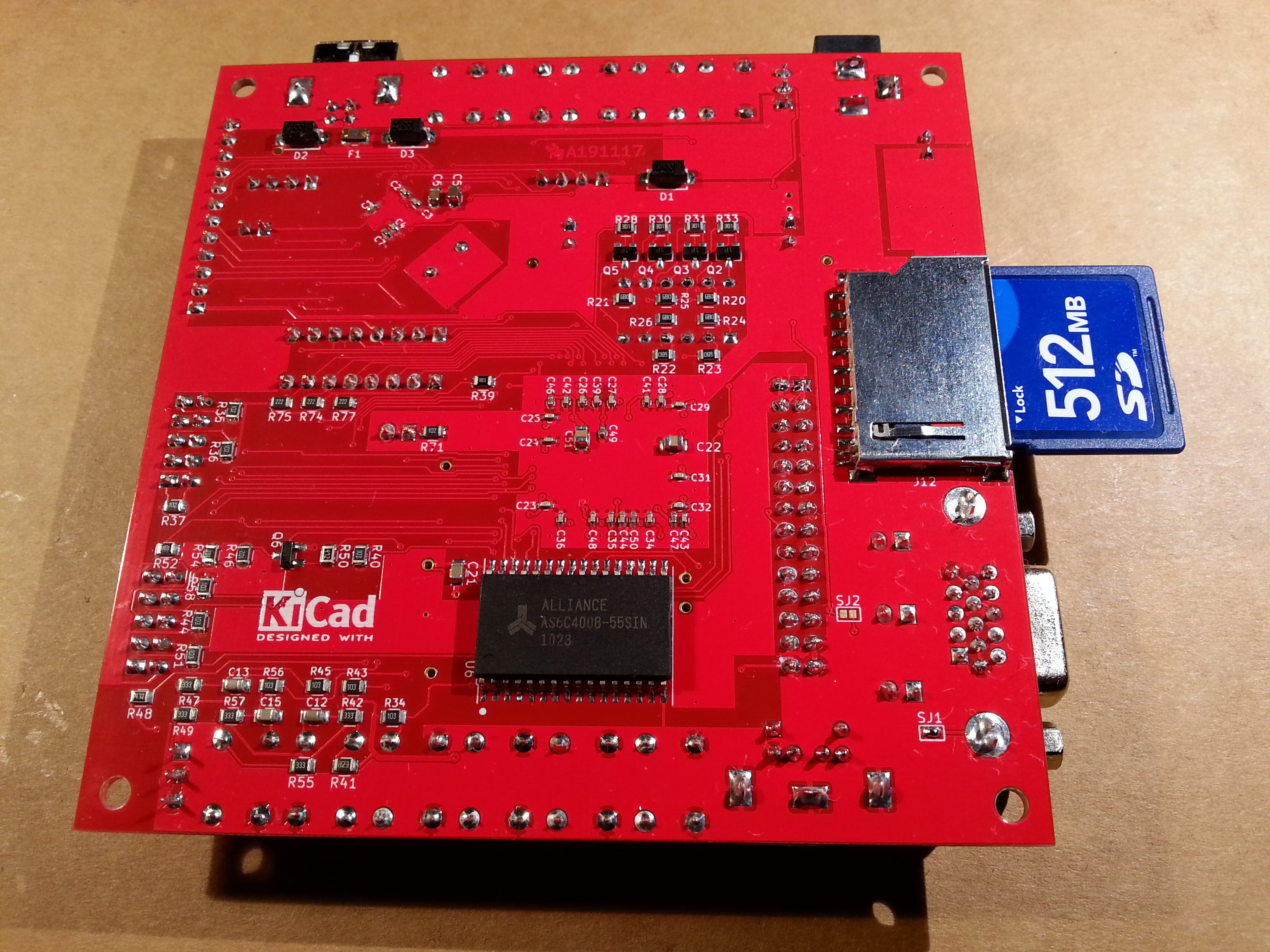
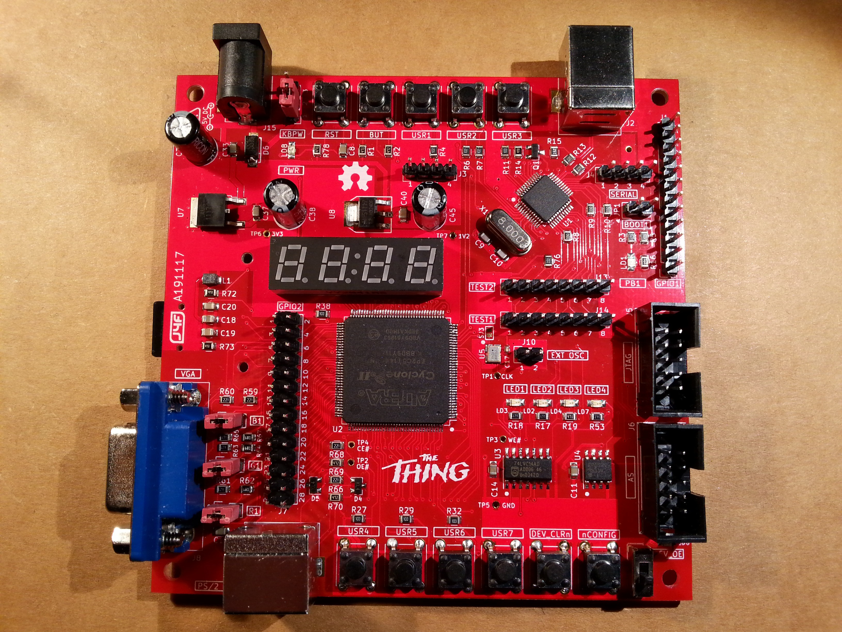
Here the details of the PCB. Please note that the PCB in the following image has an ENIG surface finish. This is not absolutely required. You can use a cheapest HASL surface finish:
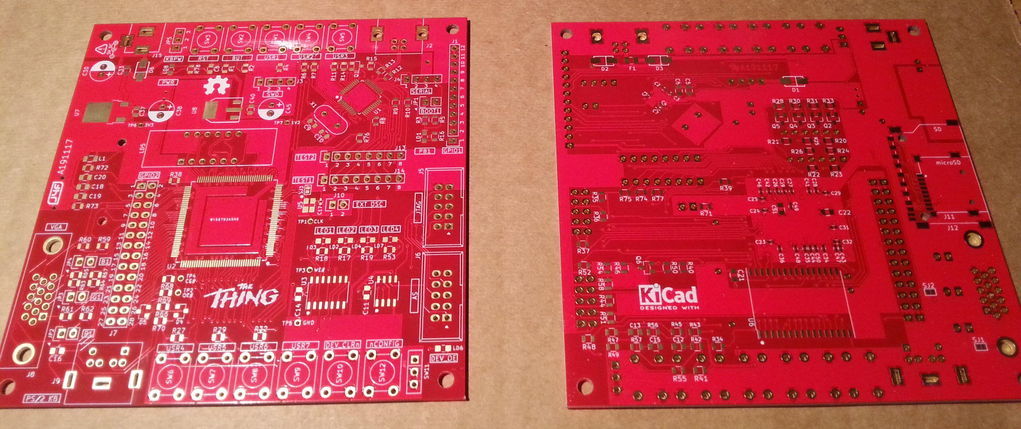
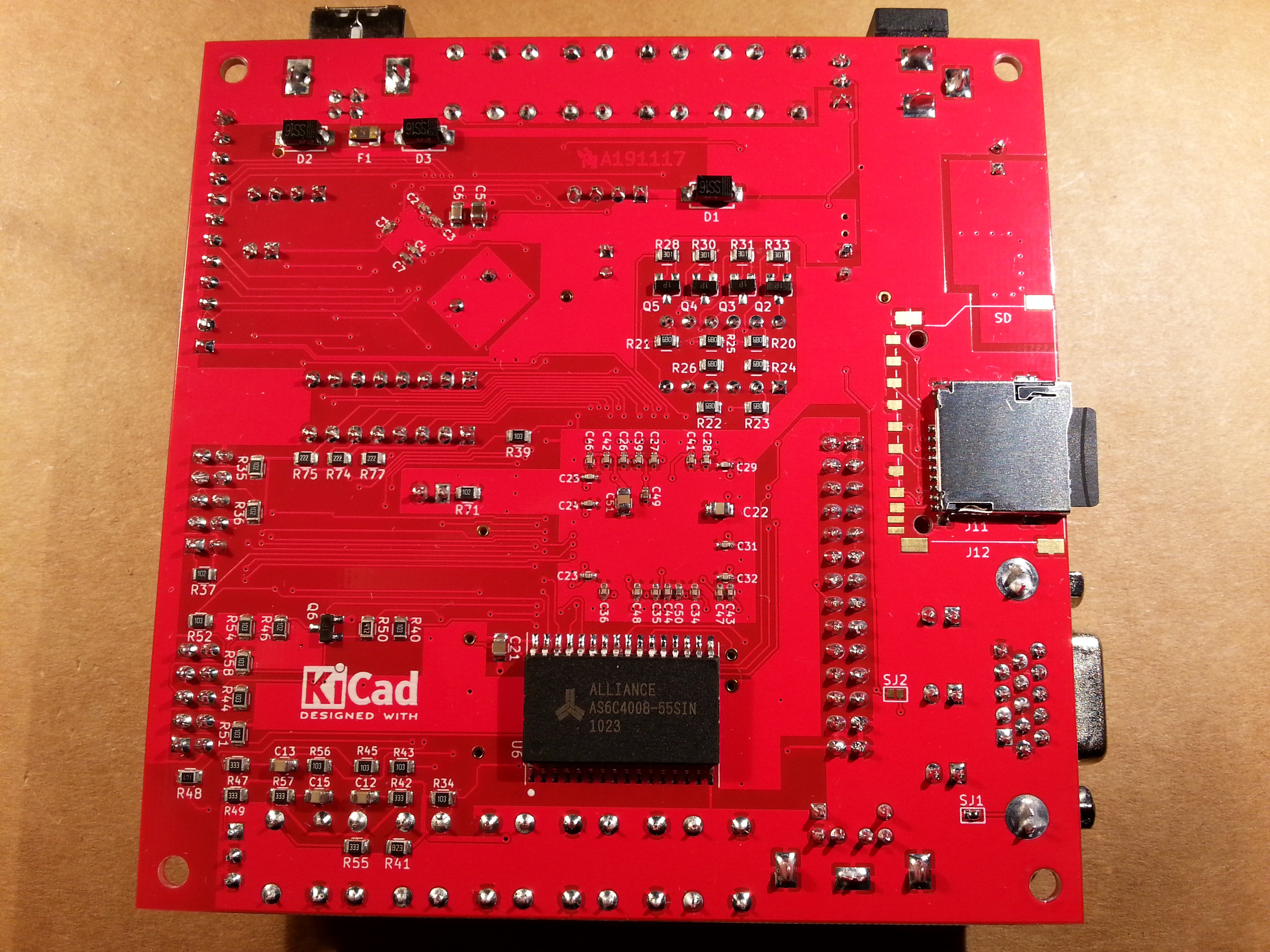
The PCB leaves the choice to solder a "legacy" SD socket (as in the previous images) or a micro-SD socket as shown in the following images:
Here The Thing in action "running" a Multicomp Z80 with CP/M 2.2 as OS:
THE STM32 ARDUINO
The STM32F103C8T6 MCU is used as "stimulus generator" or "companion" MCU for the FPGA, and is easily programmed using the friendly Arduino IDE through the USB connector.
Five push buttons (RST, BUT, USER1-USER3) and a led (PB1) are reserved to the MCU.
There is also a dedicated GPIO connector (GPIO1).
The STM32F103 MCU side is "Maple Mini" compatible, so it possible to use the STM32F103 Arduino core provided by http://www.stm32duino.com (more info here). For a short story about the Maple Mini and the stm32duino see here.
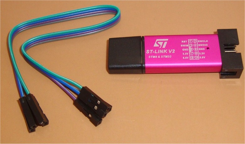
You need to flash the bootloader first using a cheap "St-Link V2" dongle through the SWD connector (or using a serial-USB adapter on the SERIAL connector. More info here).
THE CYCLONE II FPGA
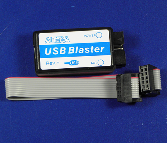
To configure the FPGA (EP2C5T144C8N) it is used the Quartus II IDE (the v13sp1 free edition is the last one supporting the Cyclone II FPGA) and a cheap "USB Blaster" dongle through the JTAG or AS connector.
To permanently store the FPGA configuration into the eeprom you can use the AS connector or also the JTAG connector with the SFL IP core as well explained in this Intel video.
A 4 digit 7-segment led display, four push buttons (USER4-USER7) and four leds (LED1-LED4, the first three are "user" led, the last one is a configuration activity indicator) are reserved to the FPGA.
On the FPGA side there are also a DEV_CLRn push button to clear all the internal FFs, a nCONFIG push button to force a configuration reload (a sort of reboot for the FPGA), and a DEV_OE switch to force all the FPGA pins in HiZ (to use the DEV_CLRn button and the DEV_OE switch you must enable them first in the Quartus II IDE).
An on-board 50MHz oscillator is present too, and there is also a connector for an external oscillator.
There are 13 I/O lines that "join" the STM32 and the FPGA, and on every of them there is a pin of two connectors (TEST1, and TEST2). In this way it is possible easily "observe" signals exchanged between them with a scope or a LA.
On this 13 I/O lines there are available various peripherals (e.g. serial, I2C, SPI) on the MCU side.
There are also others 22 GPIOs on the FPGA side (GPIO2 connector. Note that some GPIO are shared with the VGA, PS/2 and SD).
It is possible to use the Arduino STM32 "side" or the FPGA "side" as a stand-alone dev board too, with the TEST1-TEST2 connectors acting as normal GPIOs (holding the pins of the other "side" in HiZ).
SJ1, SJ2 AND SJ3
SJ1 must be shorted (it connects the VGA shield to GND).
SJ2 must be left opened (It probably will be removed in a future revision of the board).
SJ3 must be left opened (I added it only to force to Enable active if an oscillator doesn't allow to leave the Enable pin opened).
* * PROJECT STATUS * *
A lot of documentation must be written here to explain how use it...
I'm also preparing "some" Multicomp examples ready to run (including the SD image). Note that "The Thing" board HW design requires some little adaptations from the original Multicomp design reference. I'll use github for those, as I've done with the examples.
* * HOW TO GET A PCB * *
As usual I've prepared an "easy" link to get a small lot (5 pcs minimum) of PCB. The link is this one.
* * CREDITS & LICENSE * *
Multicomp VHDL are based on Grant Searle's original work, which was published with the following license:
“By downloading these files you must agree to the following: The original copyright owners of ROM contents are respectfully acknowledged. Use of the contents of any file within your own projects is permitted freely, but any publishing of material containing whole or part of any file distributed here, or derived from the work that I have done here will contain an acknowledgement back to myself, Grant Searle, and a link back to this page. Any file published or distributed that contains all or part of any file from this page must be made available free of charge.” (http://searle.hostei.com/grant/Multicomp/index.html).
All the project files (SW & HW) are licensed under GPL v3.
If you use this material in any way a reference to the author (me :-) ) will be appreciated.