 j0z0r pwn4tr0n
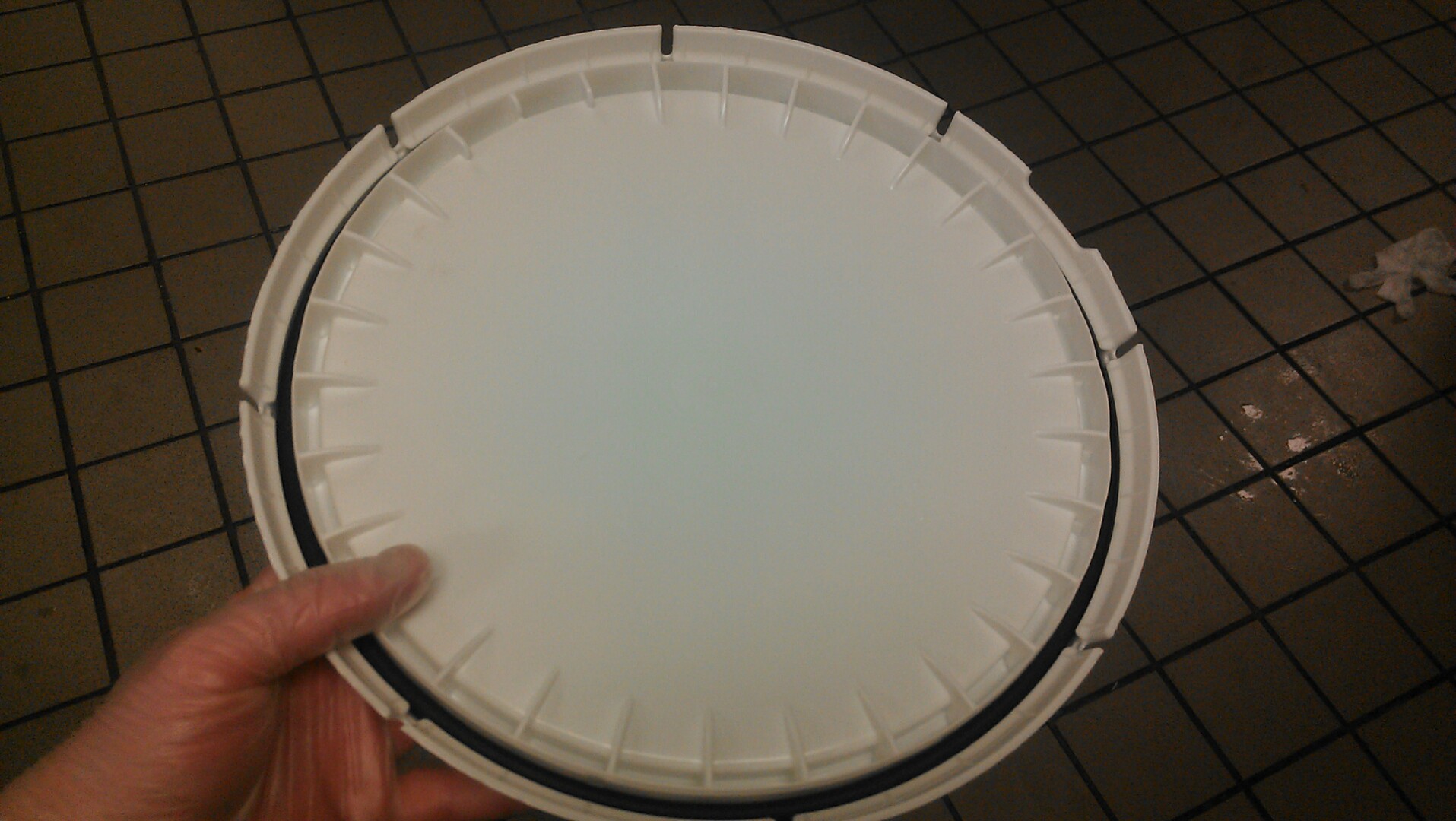
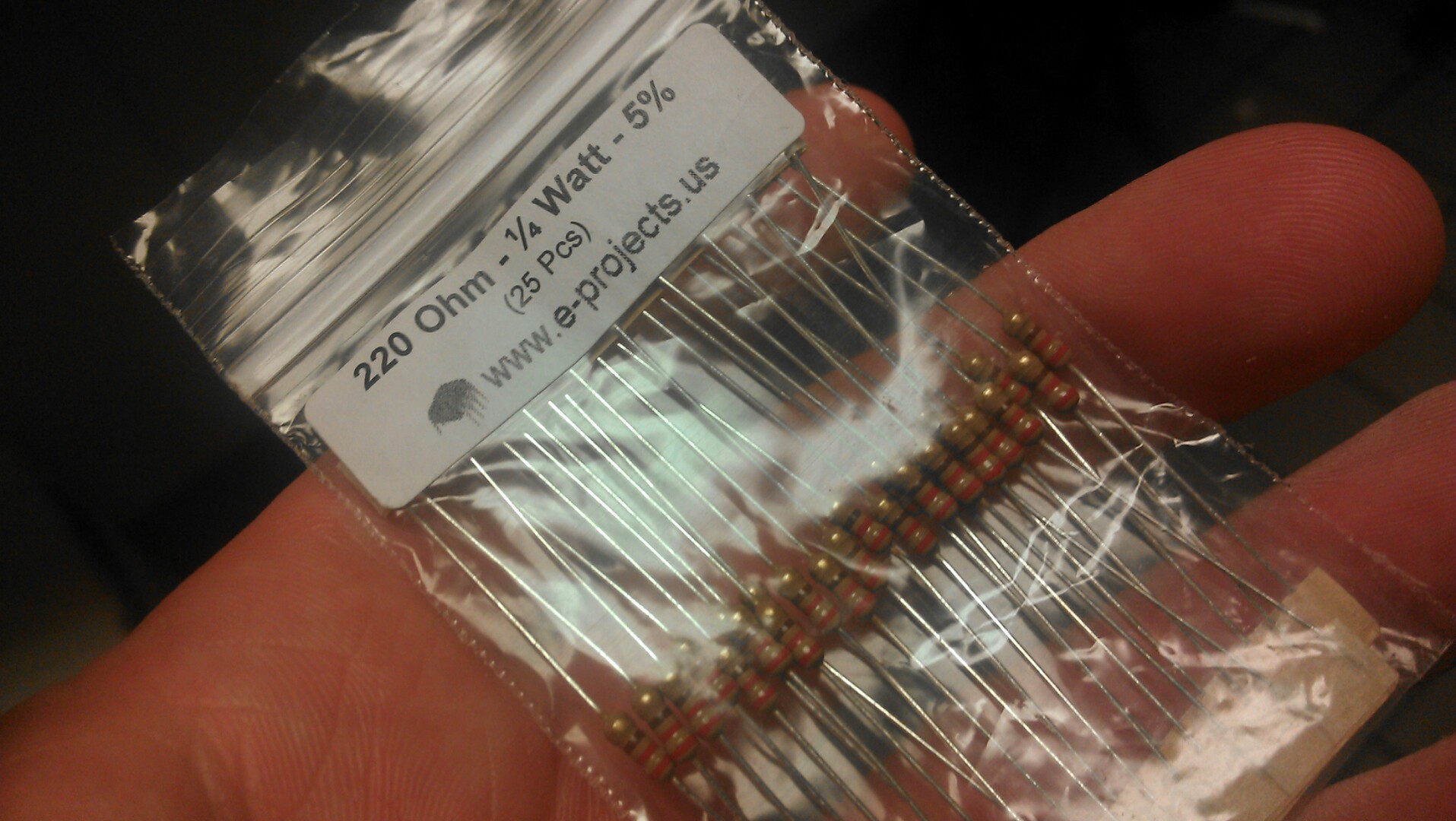
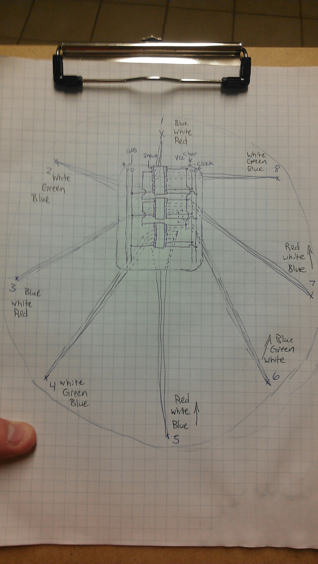
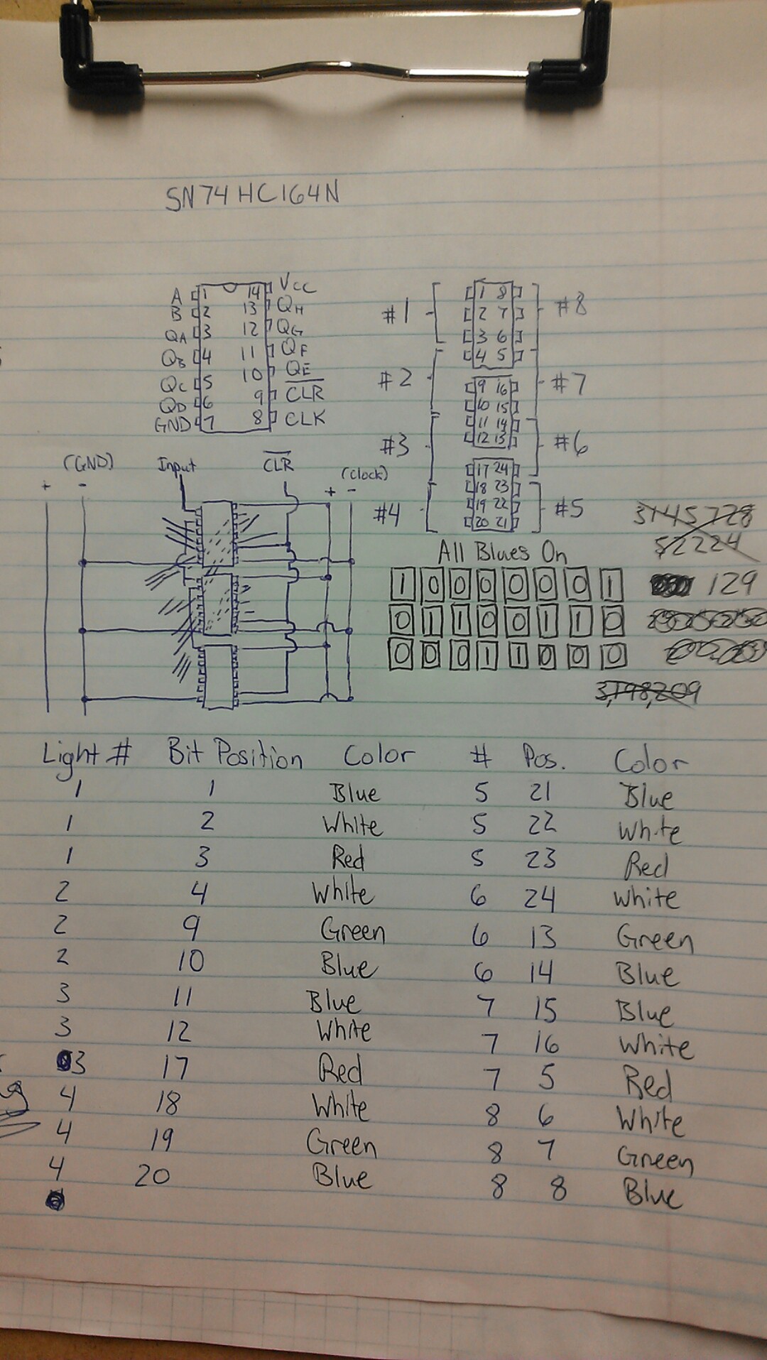
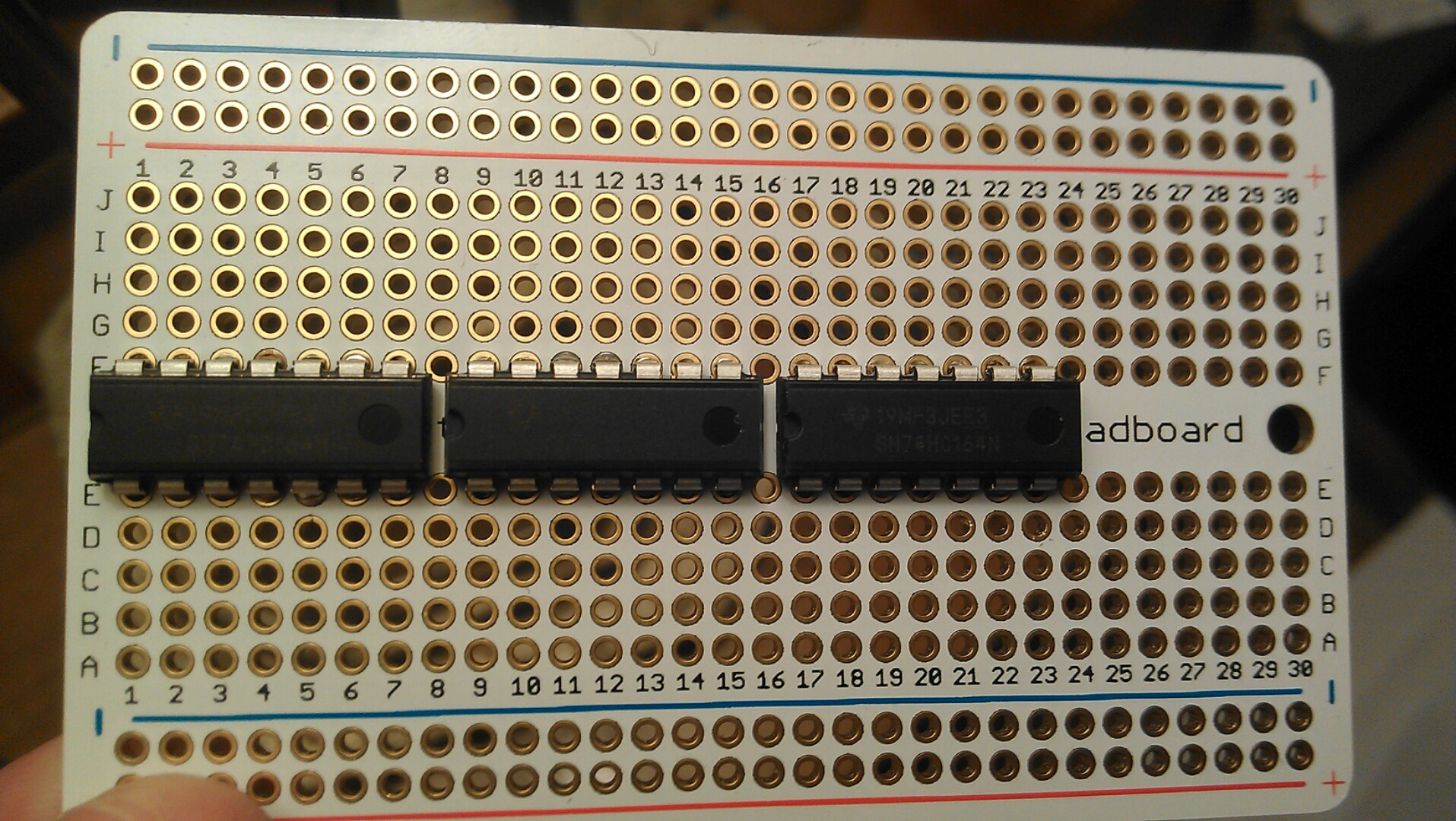
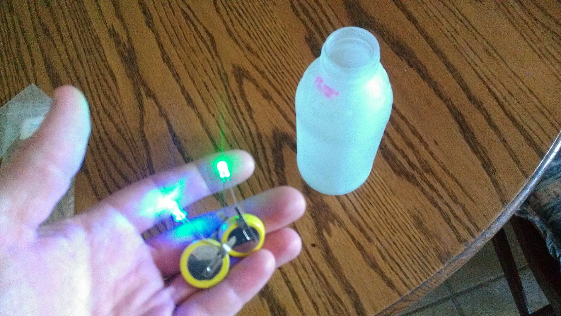
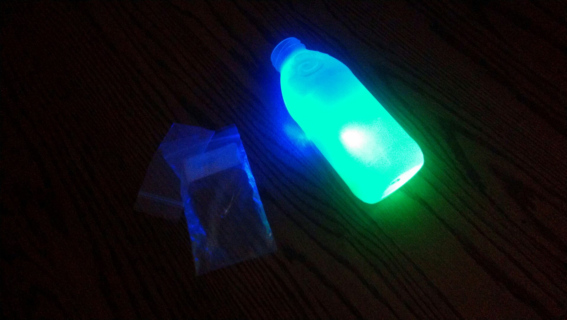
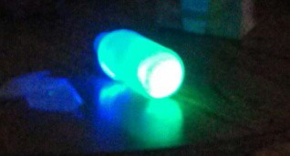
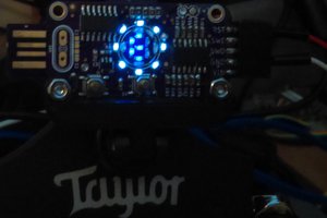
I'm using an Arduino Nano 3.0 and some shift registers to make Snapple bottles, phone cords, and LEDs into a customizable mood light. I think it would be an excellent weekend project, and can probably be completed with parts you have laying around. Also it is highly scalable, you can have more or less LEDs by just adjusting the number of shift registers to match. I'm going to try to explain as much as I can about the inner workings of the project, making it ideal for beginners to learn about the digital world. I'm going to be using it to teach my friends that are eager to learn about binary and code in general, as well as a fancy light for the h@x workbench
0%
0%
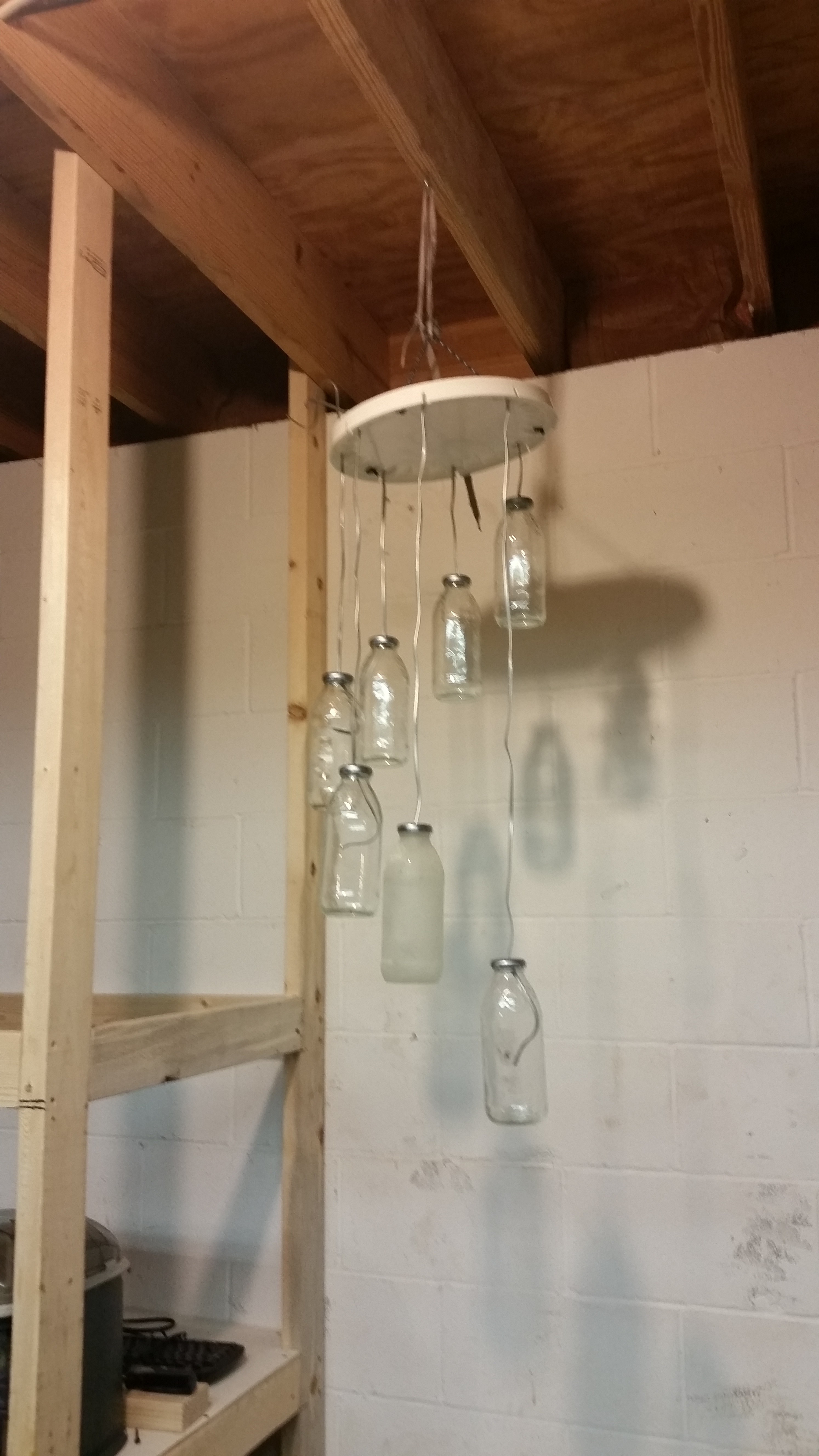
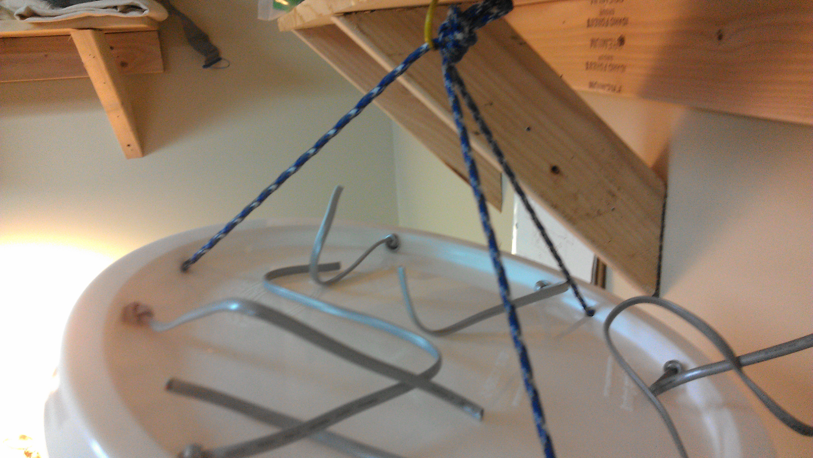
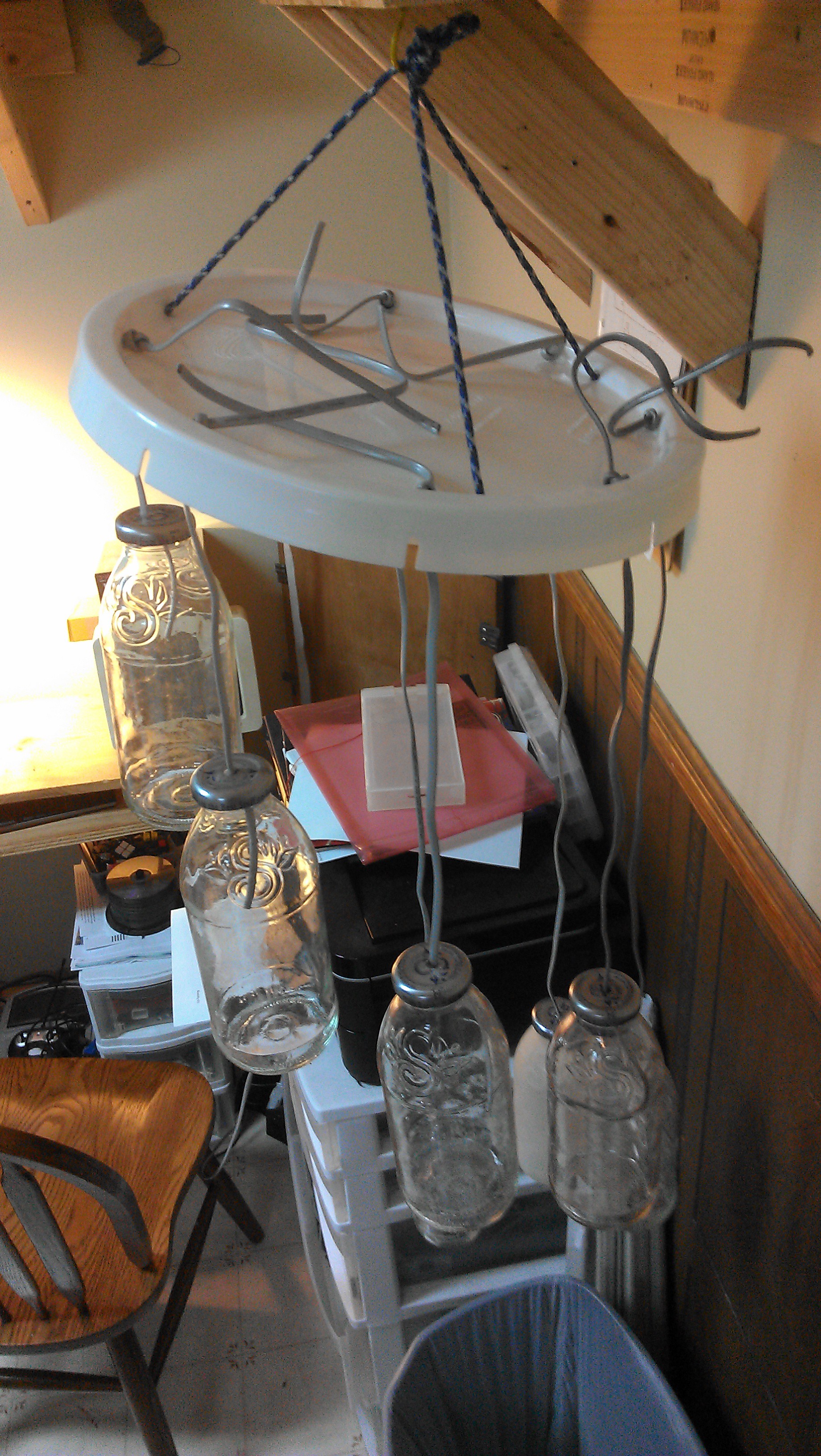
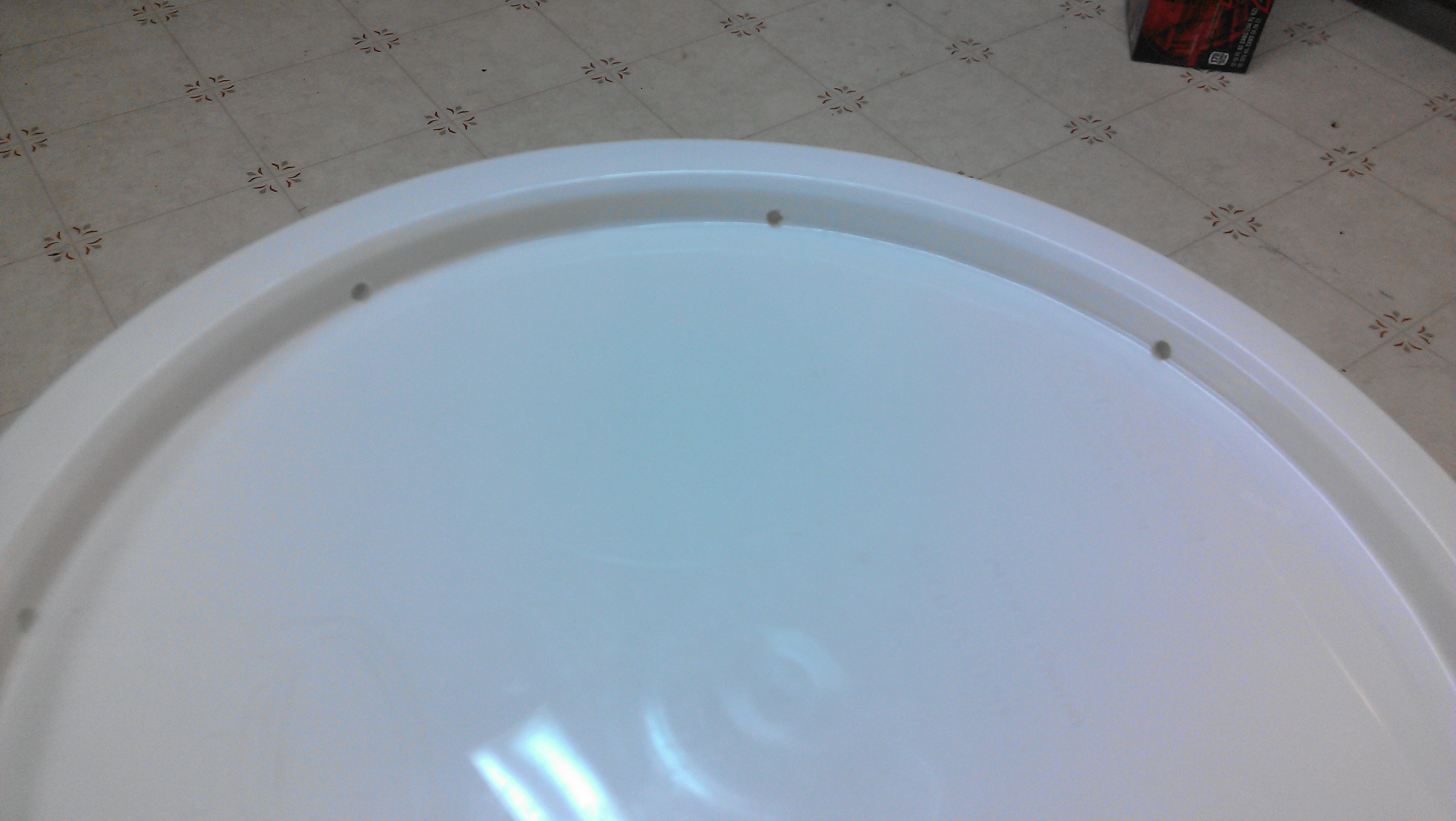
Trash light
Using throwaway materials and electronics, create a custom mood light that emphasizes recycling/upcycling
Become a Hackaday.io member
Already have an account? Log in.
Just one more thing
To make the experience fit your profile, pick a username and tell us what interests you.
Pick an awesome username
hackaday.io/
Your profile's URL: hackaday.io/username. Max 25 alphanumeric characters.
Pick a few interests
Projects that share your interests
People that share your interests

 ZaidPirwani
 ssutton4455
 rrace001