 marciot
The Inspiration:
My project was inspired by Paul Nylander's "Loxodrome" wall sconce (http://bugman123.com/). I had recently bought my first 3D printer on Kickstarter and I knew that the Loxodrome sconce was something I wanted to tackle.
Once I became a little more experienced in 3D printing, I set out to see if I could recreate Paul's work. Having found kitwallace's OpenSCAD implementation of the Loxodrome, I printed a small version and made a comically jury rigged mockup using some plywood, a white SMD LED, a power supply and copious amounts of blue painter's tape (because I didn't want to drive nails into my wall!).
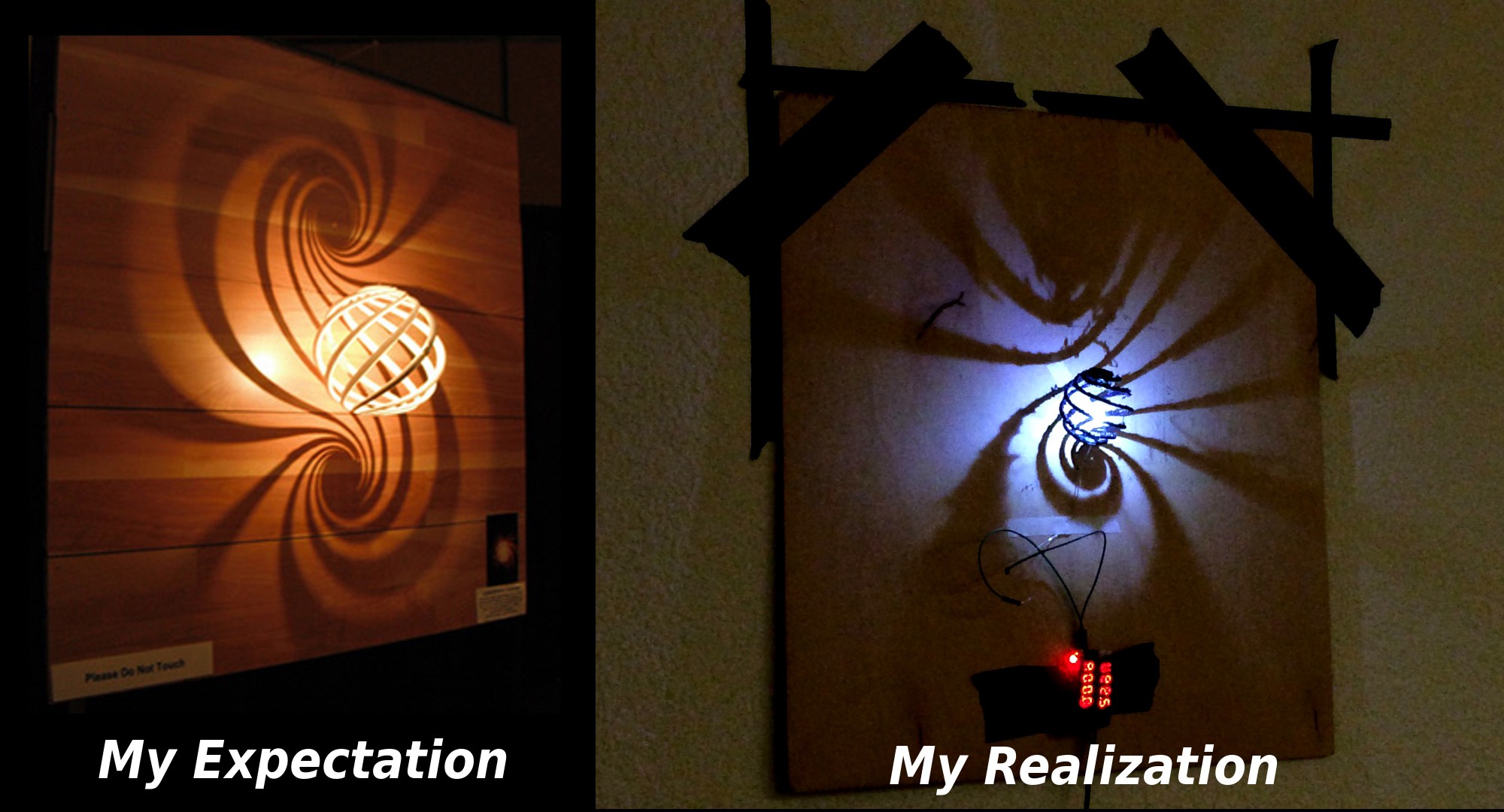
As silly as it looked, it got me thinking about how to take it to the next level.
Taking the Loxodrome for a Spin:
Not soon after I put together my mockup, I realized it would be much better if the Loxodrome could turn on its vertical axis, therefore projecting a rotating pattern of shadows on the wall.
This presented a challenge, as the Loxodrome could no longer be attached directly to the board, nor could the LED be attached to a spiral arm of the Loxodrome. For it to rotate, the Loxodrome would need to turn freely, with the LED and associated wiring suspended independently inside the rotating shell.
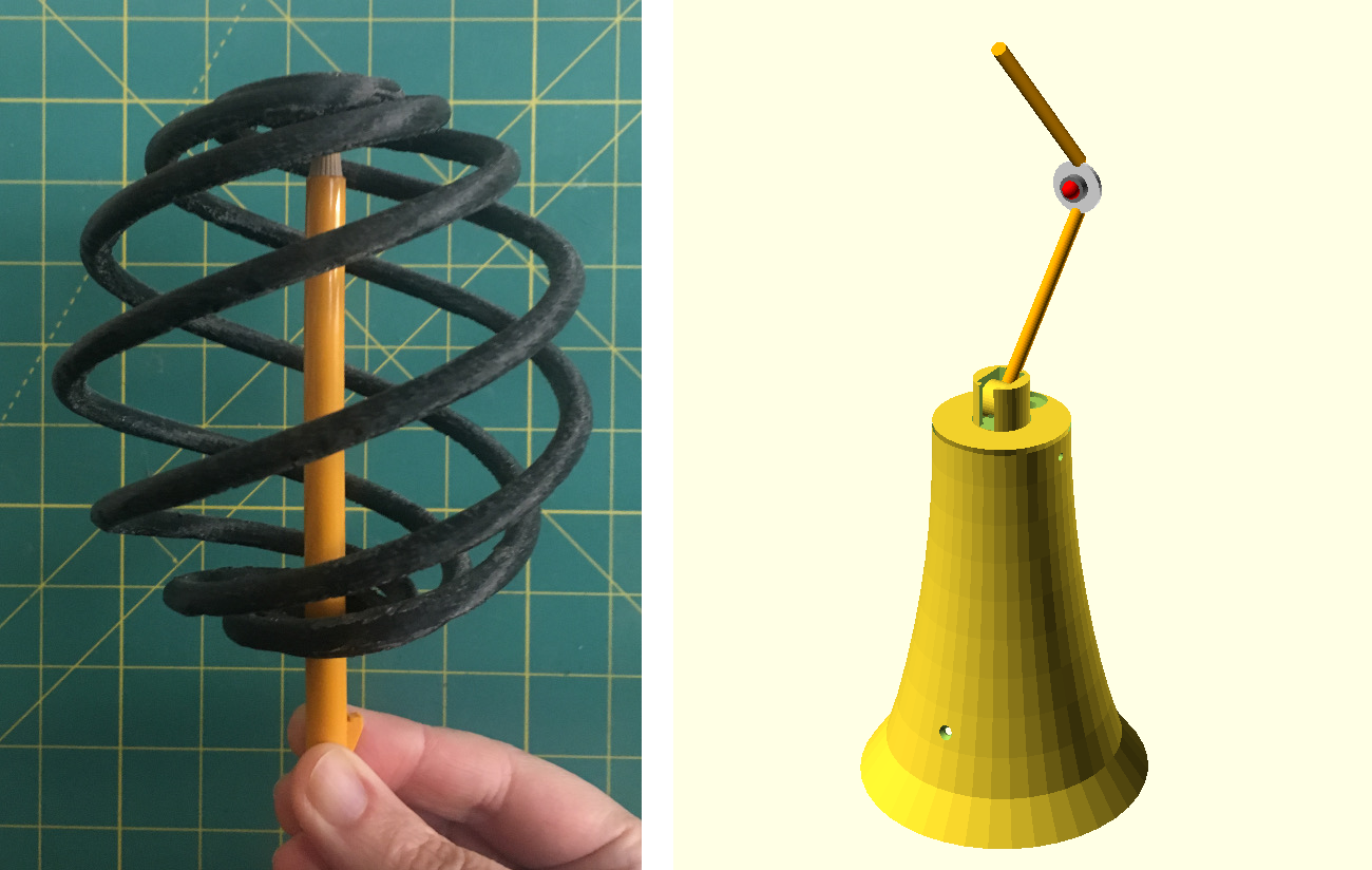
I modified the Loxodrome in OpenSCAD to add a 18 mm diameter opening on the bottom and a small cap at the top that would allow the Loxodrome to balance and rotate freely on the tip of a pencil.
Having found a way to make it spin, I decided to make my next prototype into a free standing table lamp.
My original lamp consisted of a tapered base with a bent piece of copper tubing on top. The copper tube would support a LED, as well as provide a tip for the Loxodrome to rest and spin around on. I replaced the dim SMD LED with a 1W white LED star for improved brightness.
Trying to Make it Turn on its Own Made my Head Spin:
I now had a freely spinning Loxodrome and a way to mount the LED inside it. However, the Achilles' heel of this design was the fact that the Loxodrome was hanging loosely on the pivot point. Making it turn on its own proved to be challenging.
At first, I mounted small ring of magnets on the bottom of the Loxodrome near the opening and tried to use a hand-wound solenoid to make the Loxodrome to turn. This merely caused it to stutter and vibrate.
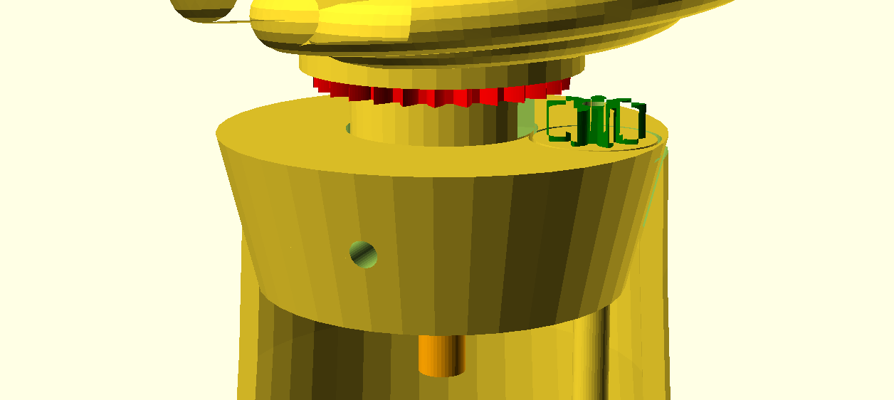
Shelving that idea, I replaced the magnets and solenoid with a toothed ring (red) that would mesh with a smaller gear. The smaller gear (green) was attached to a shaft leading to a TYD-50 AC synchronous motor I hid in the base. Unfortunately, because the Loxodrome was hanging freely from the top, it could swing away from the teeth of the gear, often skipping a tooth rather than turning. Sometimes, because of roughness in the printed parts, it would freeze up momentarily, only to jerk loose, leading to a very jumpy, unsatisfying motion. Although it showed that using gears had potential, at that point it was far from an effective solution.
For a while, I put the project aside until further inspiration came to me.
Improving the Design, With Better CAD Tools:
My initial failures taught me several lessons. Hanging the Loxodrome on a pivot point from the top made it rickety and wobbly. This made the geared mechanism unreliable.
For my next iteration, I knew I wanted to support for the Loxodrome firmly from below and to transmit torque to it from the motor via an internal gearbox. I also needed to have a non-rotating central shaft that would support the LED arm and serve as a conduit for the wires to the LED.
I also wanted to make it easier to build. In my original design, I used a copper tube to hold up the LED and epoxy to mount the LED to the tube. To shape the tube I had to cut notches in it with a Dremel, flattened parts with pliers, and roughly bending it into shape. It was a lot of work and it took a lot of adjustments just to get it to fit inside the Loxodrome. Despite my best efforts, it would often touch the Loxodrome, preventing it from turning.
For the new design, I wanted something more rigid where all the structural elements came out of a 3D printer ready to assemble.
I also wanted to incorporate a 608 roller skate bearing into the design to make it turn more freely and smoothly than the original. As a further constraint, I wanted to reuse most of the 3D printed parts from the original lamp. This limited the space I had to work with and meant the mechanism needed to be small enough to fit inside the original lamp's base and it had to snap fit to the original 3D printed Loxodrome.
Since I had made my original prototype, I had learned FreeCAD, so I had the option of using that tool instead of OpenSCAD. This new tool allowed me to build a much more effective gearing system that contained a 608 bearing, provided a snap-on fit for the Loxodrome, and had the necessary stationary central pillar for the LED support arm and wiring. Everything was self contained in a central module that slid neatly into the original housing.
Aside from the wiring and electrical components, this new design was fully 3D printed and was much easier to assemble than the original. The LED support arm has a notch for a four position female DuPont connector that provides power for the LEDs. The LED modules are removable. This is important since the bottle caps I use as heatsinks for them are too large to pass through the opening at the base of the Loxodrome. Instead, they are connected last once the lamp is assembled.
The LED modules consists of a LED star glued to a bottle cap using thermal epoxy. On the back, I epoxy a four pin male DuPont connector. This mates to the female connector on the LED mounting arm. This happens once the Loxodrome is already in place.
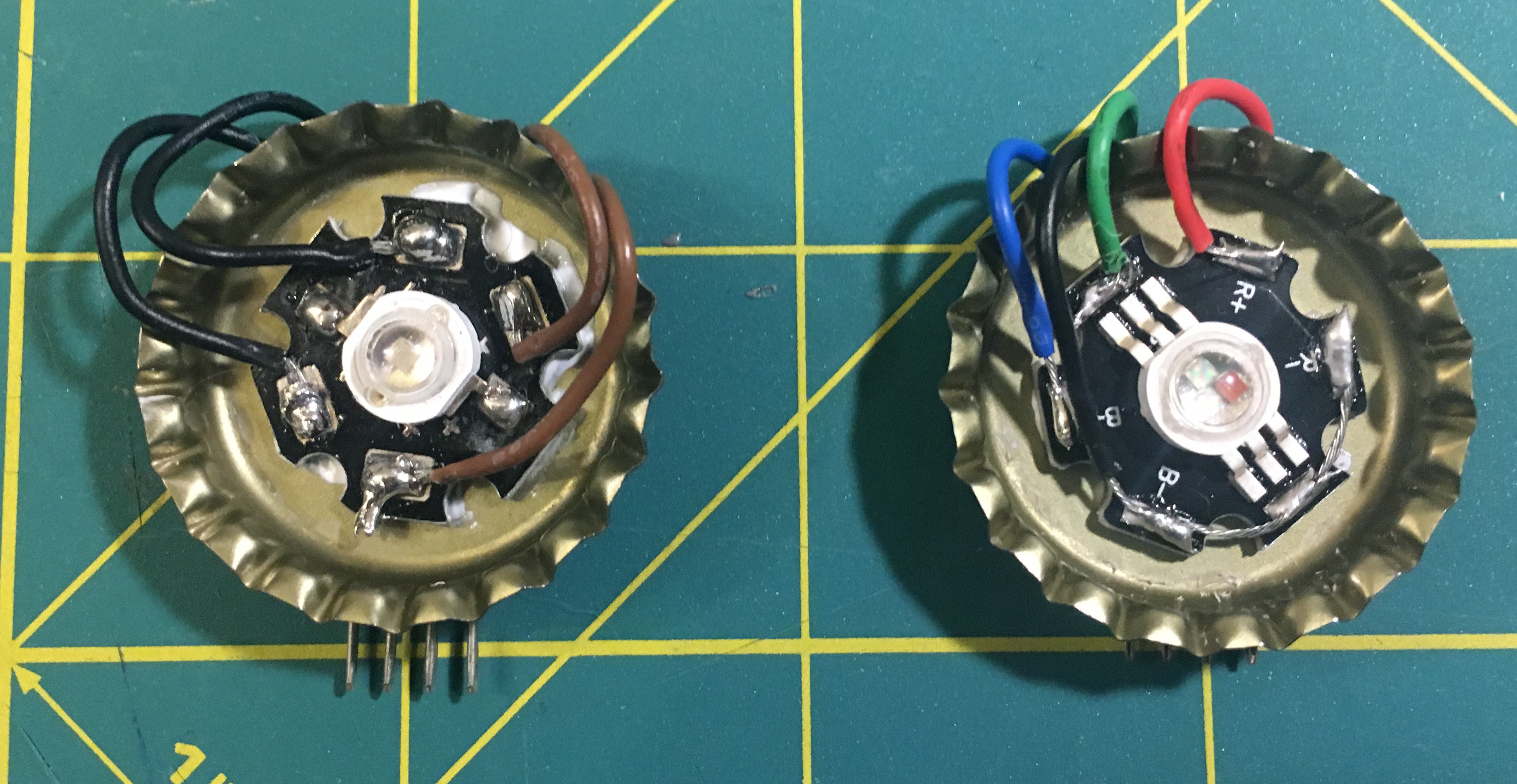
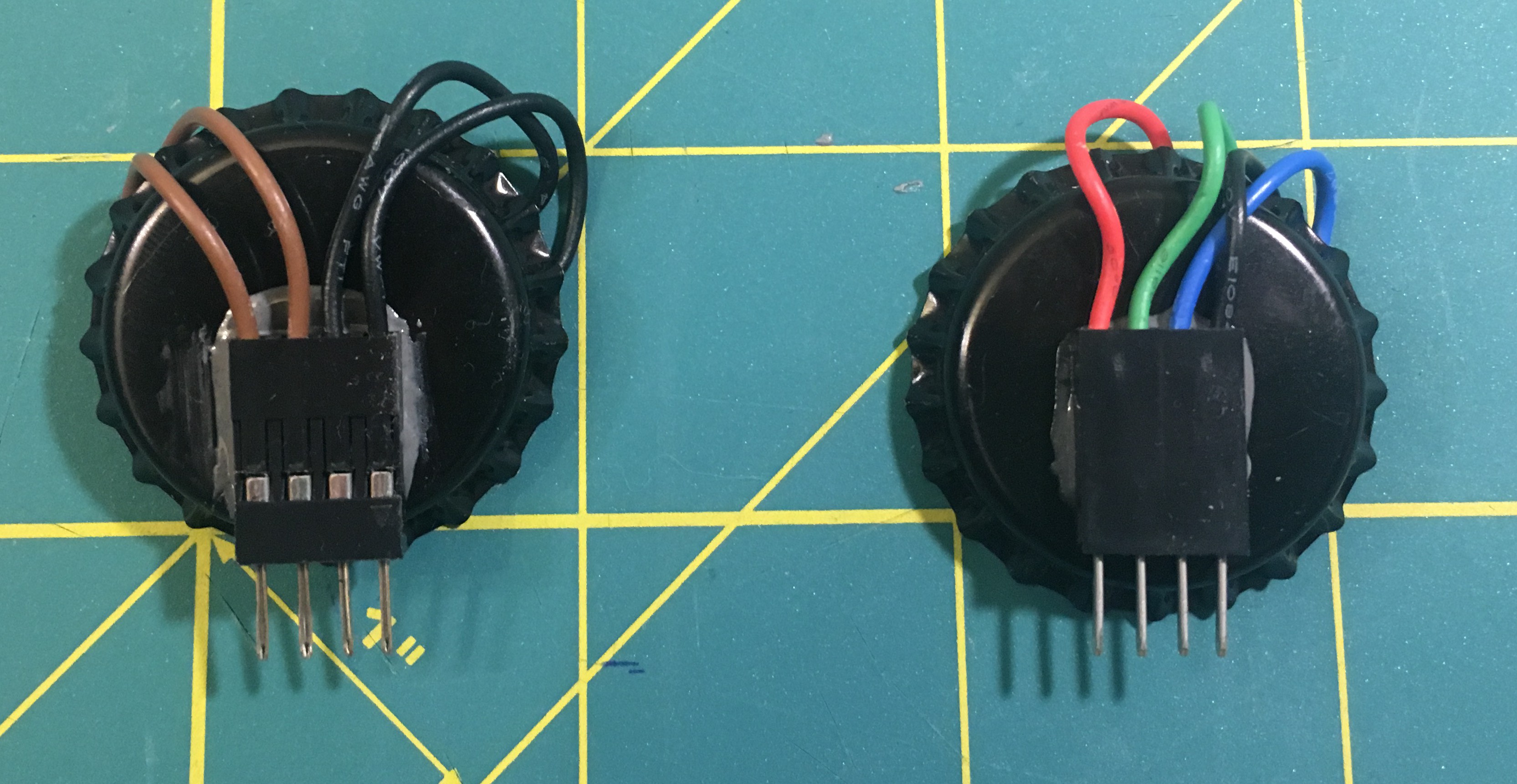
Since the connector has four pins, I can drive an RGB LED module as well as double up on the pins to deliver more current to a single color LED star.