Close
0%
0%

Split-flap display

A 3d printed split-flap display using a 28byj-48 stepper motor

Similar projects worth following
A 3d printed 12 digit split-flap display using a 28byj-48 stepper motor. The motor was moved to the back to provide a slimmer profile. A 3d printer endstop module is used to check for the position of the drum with each rotation.

Several of these modules can be put together for a clock or counter

The current display has 12 flaps, meaning 10 numbers, a blank face and one other character.

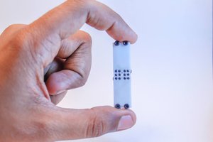
The mechanical part of this project is finished, next up is code and electronics in order to create a clock out of these. The plan is to modify these cheap steppers to a bipolar layout, seen here. And then use off the shelf electronics used in cheap cnc/3dprinter/plotter such as these or just plain stepsticks.

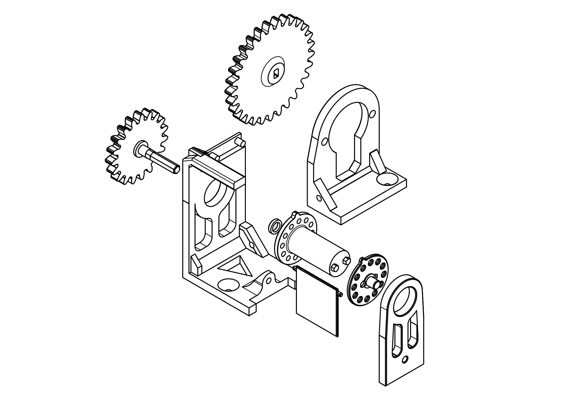
Since I've entered this in the 3d printed gears contest, I'll mention that the gears used to drive the mechanism were generated using Fusion 360's build in gear generator. I've used this generator in multiple projects and can recommend it to easily generate simple spur gears. 

simplify3d_stl - 56.04 kB - 02/06/2019 at 15:51

Download

simplify3d_stl - 72.54 kB - 02/06/2019 at 15:51

Download

simplify3d_stl - 474.98 kB - 02/03/2019 at 19:29

Download

simplify3d_stl - 303.60 kB - 02/03/2019 at 19:29

Download

simplify3d_stl - 318.54 kB - 02/03/2019 at 19:29

Download

View all 9 files

  • 1 × 28byj-48
  • 2 × 625zz bearing
  • 1 × mechanical endstop

View project log

Enjoy this project?

Share

Discussions

Sophi Kravitz wrote 02/22/2019 at 15:04 point

Neat project. I didn't realize that Fusion had a built in gear generator. Off to try it now :)

  Are you sure? yes | no

adamc wrote 02/16/2019 at 00:42 point

I've managed to build one and get it running, I did have a bit of trouble with the drum and peg. I redid it slightly as it was slipping a little, also had to build out the nub on the drum to press the NC stop a little more as mine wouldn't trigger. I'm also unsure where the spacer should go?  Does it go on the gear end of the drum? I noticed that the flaps would touch the microswitch on the end stop I've got in there. The other bit I'm looking at is that the flaps hit the bolt holding the motor in, so might recess that bolt a bit , although it doesnt seem to be a problem. I've also put a 2mm bolt through the middle of the drum and the drum2 disk which helps hold it together. I've got a homing routine done now and working on positioning the flaps now. It's working really good :)

(ignore the spacer question, I've just seen it on the exploded diagram)

  Are you sure? yes | no

jonas wrote 02/16/2019 at 05:48 point

the nubs worked fine with me weird.

About the bolt hitting the flaps, I've actually just removed the bolt. It works fine without the motor sits snugly and I didn't want to move it backwards because that way the unit would be even deeper than it is now.

Great that you are thaking it further! I haven't had the time the last couple of weeks to work on it.

  Are you sure? yes | no

adamc wrote 02/18/2019 at 14:13 point

hey, just to let you know i have it working with a Wifi Wemos as well now.  I'm using it to display recent twitter users that I follow. I'm going to post the code up on instructables most likely and checking that its fine to include the modded files I've done with links and credits back here of course

  Are you sure? yes | no

jonas wrote 02/18/2019 at 16:32 point

As long as you attribute and link back its fine. I'm looking forward to seeing what you've done with it.

  Are you sure? yes | no

adamc wrote 02/14/2019 at 19:27 point

great project, I'm printing one now. Was the mult-part mount and base etc. done in such a way to avoid supports with printing? I wondered if it was possible to print the main unit as one piece with supports perhaps for the arm that holds the flaps back?
I've ordered up some endstops, but also wanted to know what bearings you had used, were they 625ZZ or similar  16mm OD 5mm thick and 5mm I/D?

  Are you sure? yes | no

jonas wrote 02/14/2019 at 21:01 point

hey thanks. Well yes I try to design in such a way as to avoid supports. You could try to do otherwise offcourse, I just try to avoid it. 625zz are the bearings I used.

  Are you sure? yes | no

octebra wrote 02/14/2019 at 02:17 point

Great project, how do you power the stepper as a motor I am in the process of designing and building a wooden gear clock and I need a controllable motor to turn the gears. 

  Are you sure? yes | no

Brian Lough wrote 02/10/2019 at 11:36 point

I love this Jonas! I was actually looking for something like this week and couldn't find anything.

I have a question regarding keeping track of where you are, you are using the end stop to count how many flaps have gone past is it? Or is it triggered by the nub on the top of the wheel that the flaps are attached to? 

  Are you sure? yes | no

jonas wrote 02/11/2019 at 06:21 point

It is triggered by the nub, so it senses its position once per rotation.

  Are you sure? yes | no

Brian Lough wrote 02/14/2019 at 11:49 point

I printed one of these out, I'm just waiting for the end stop and bearing to come from China (so it will be a while :)

  Are you sure? yes | no

fabian wrote 02/07/2019 at 11:25 point

can You increase a speed?

is possible to create big number of chars?

for example 127 ascii code?

  Are you sure? yes | no

jonas wrote 02/07/2019 at 19:44 point

the speed in the video is about half of the maximum, but I like the leisurely speed

you can definitely have split flap display that have a full range of numbers and letters but I've never heard of anything beyond that.

  Are you sure? yes | no

fabian wrote 02/07/2019 at 22:25 point

127 chars

  Are you sure? yes | no

Jon wrote 02/13/2019 at 17:30 point

  Are you sure? yes | no

Martin wrote 02/05/2019 at 12:19 point

You do not even need to cut the connection to drive the motor bipolar. There should be zero net voltage at the connection between the two phases. But in this low power application I would not bother about bipolar drive or is it THAT weak?

  Are you sure? yes | no

jonas wrote 02/05/2019 at 19:16 point

Really? I figured there would some interference. I'll definitely test it out thanks for the tip

  Are you sure? yes | no

Martin wrote 02/07/2019 at 09:32 point

Of course it depends on the symmetry of the windings. But you can easily test this by measuring the resistance (and if possible the inductance values) of the half windings.

  Are you sure? yes | no

andres ortiz wrote 02/04/2019 at 22:39 point

well done, I love it!

  Are you sure? yes | no

Dan Maloney wrote 02/04/2019 at 15:59 point

Hey, that's awesome! Do you think the flaps are thick enough to take debossed characters? Or are you planning to just add labels to create the characters?

  Are you sure? yes | no

jonas wrote 02/04/2019 at 20:10 point

the idea is to create the characters using different colors over multiple layers. the flaps are 1mm think so I hope thats enough. If it isn't, well labels are an alternative as you said. 

  Are you sure? yes | no

Similar Projects

Does this project spark your interest?

Become a member to follow this project and never miss any updates