 Alastair Young
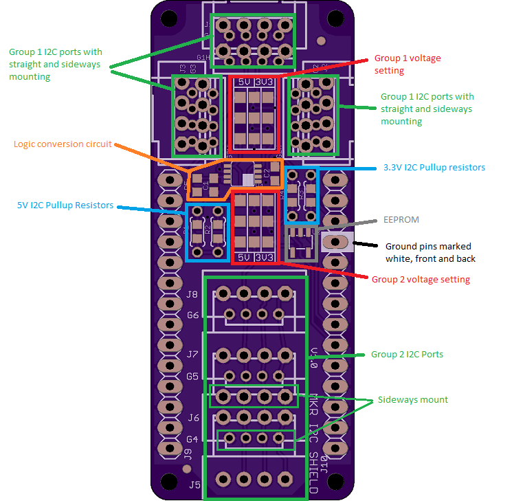
The connector mounting locations include 6 locations for Grove and 7 locations for 0.1" - specifically spaced for the locking Molex SL connectors. In each style 4 of the positions have an offset set of holes for the 90 degree "sideways" versions. This does give the board a bit of a Swiss cheese appearance, but it works.
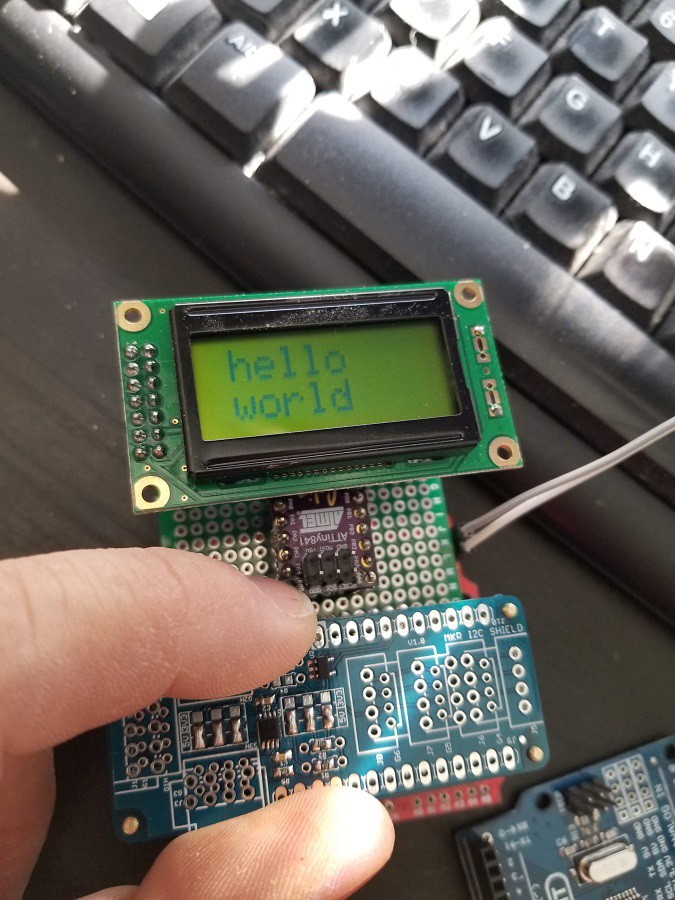
The ports are divided into two groups and each group can be set to either 3.3V or 5V operation with solder jumpers, and a logic level conversion chip is included. Both the 5V and 3.3V can have separate pullup resistors in SMD or thru-hole forms. As the MKR boards include 4.7k pullups on the 3.3V I2C pins these will be left unpopulated for 3.3V and will be populated with 4.7k for the 5V side. Sometimes 4.7k is not the value you actually need, so this gives you the flexibility to do some tuning.
Straight connectors can be mounted on top or underneath the board allowing the board to be on the top or bottom of the stack. The sideways connectors allow it to be used in the middle of the stack with a reduced port count. Due to the polarity of the connectors the sideways Grove connectors must be mounted on top and the sideways Molex underneath. In all stacking configurations I have tried this works fine.
This will be supplied with your choice of connectors and stacking headers.
As the MKR Arduinos use the SAMD21 chips which do not have EEPROM, a footprint for an I2C EEPROM chip is included.
Connector locations:


 Arduino Enigma
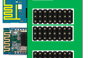
 Craig Hissett
Thanks for the feedback. I try and think how people will use my products up front, and work in the flexibility. It saves revisions later. The boards are ordered with some silkscreen improvements from the prototypes shown. It is very easy to solder the connectors in the wrong way (I did that on the very first one and had to desolder and redo) so I'll be aiming to make the documentation as clear as possible.