 Paul Gould
Background
Autodesk Inventor Parametric Design Cycloidal Gear (from my other project)
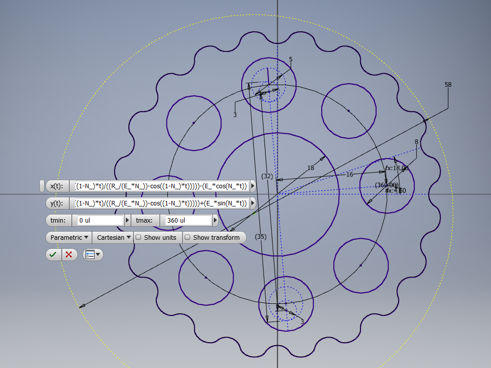
N_ (number of rollers)= 21 ul
number of teeth = number of rollers - 1
E_ (eccentricity) = 1 mm
Rr_ (radius of rollers) = 2 mm
R_ (radius of Rotor) = 25 mm
x(t) = (R_*cos(t))-(Rr_*cos(t+atan(sin((1-N_)*t)/((R_/E_*N_)-cos((1-N_)*t)))))-(E_*cos(N_*t))
y(t) = (-R_*sin(t))+(Rr_*sin(t+atan(sin((1-N_)*t)/((R_/E_*N_)-cos((1-N_)*t)))))+(E_*sin(N_*t))
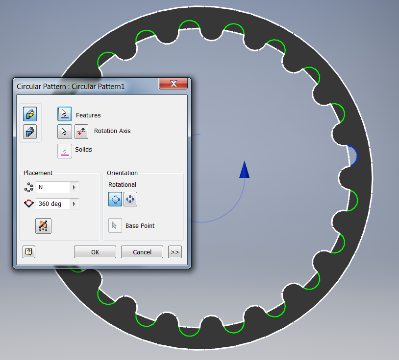
Outer ring design (replaces rollers)
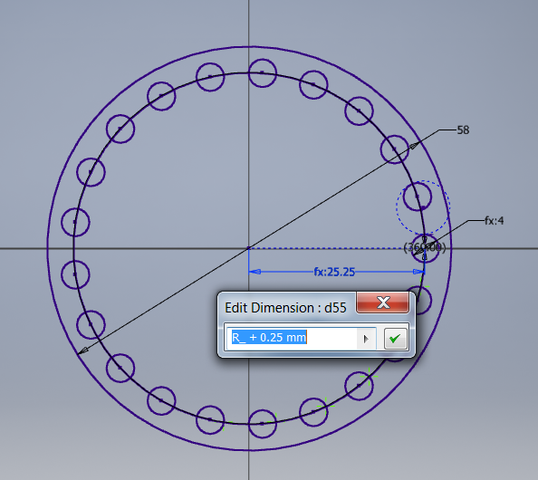
The + 0.25mm is the tolerance added to on my 3D printer to make it work nicely.
The whole actuator consists of a brushless motor, motor position sensor, cycloidal gearbox, joint position sensor. All of this is controlled by my custom BLDC controller.
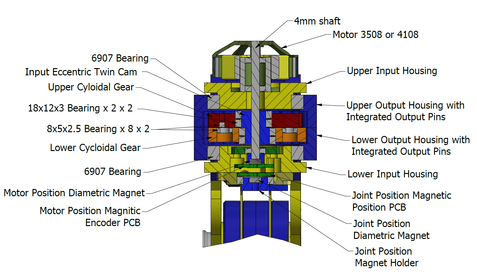
Cutaway of the Upper Actuator
This actuator is a similar to the ones used by the legs. It is just a bit smaller. It is only used to "swish" the tail side to side. This type of actuator is 75mm high. This is way too wide to be used for the tail's lower joints.
Discussions
Become a Hackaday.io Member
Create an account to leave a comment. Already have an account? Log In.