0%
0%
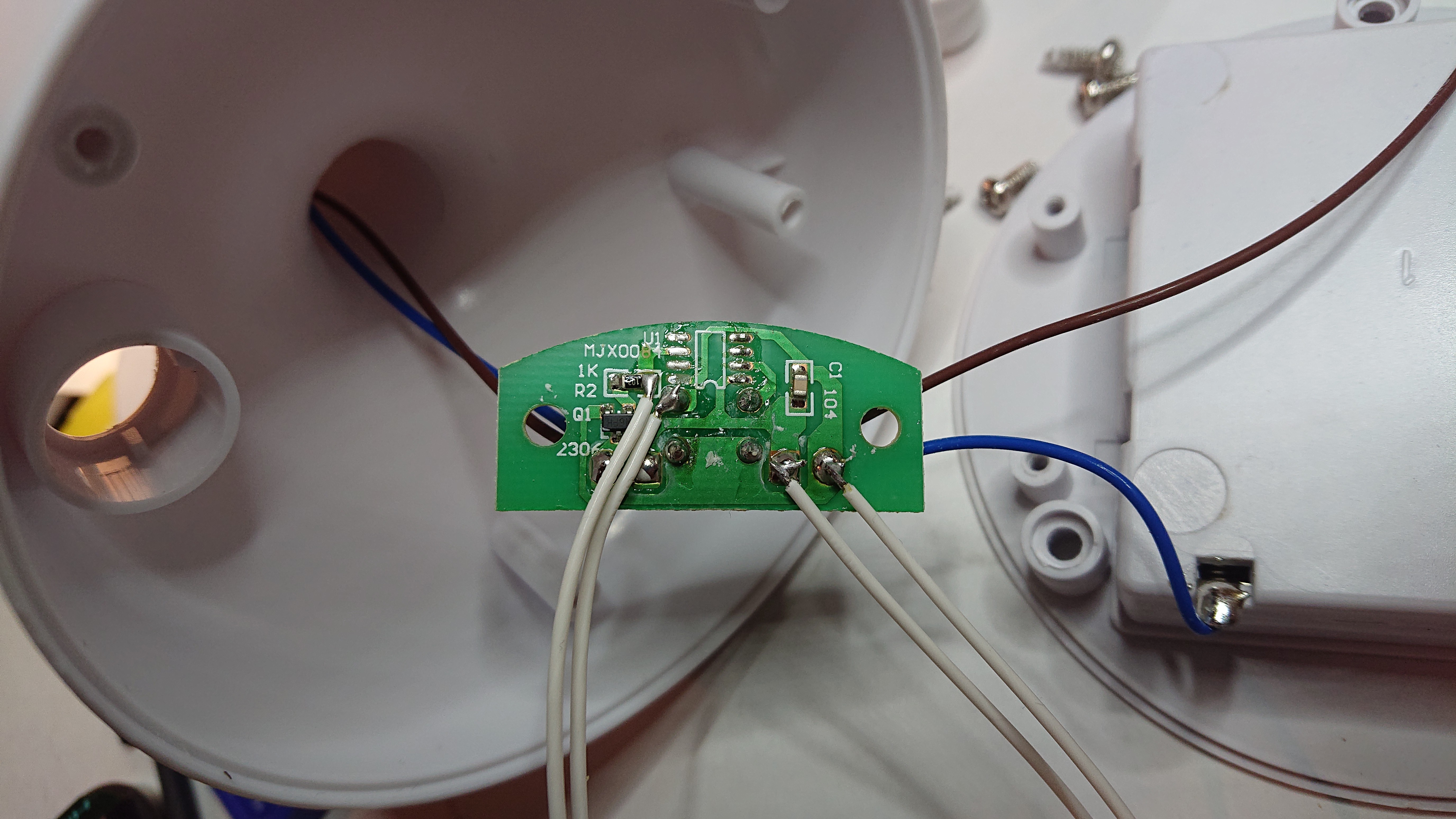
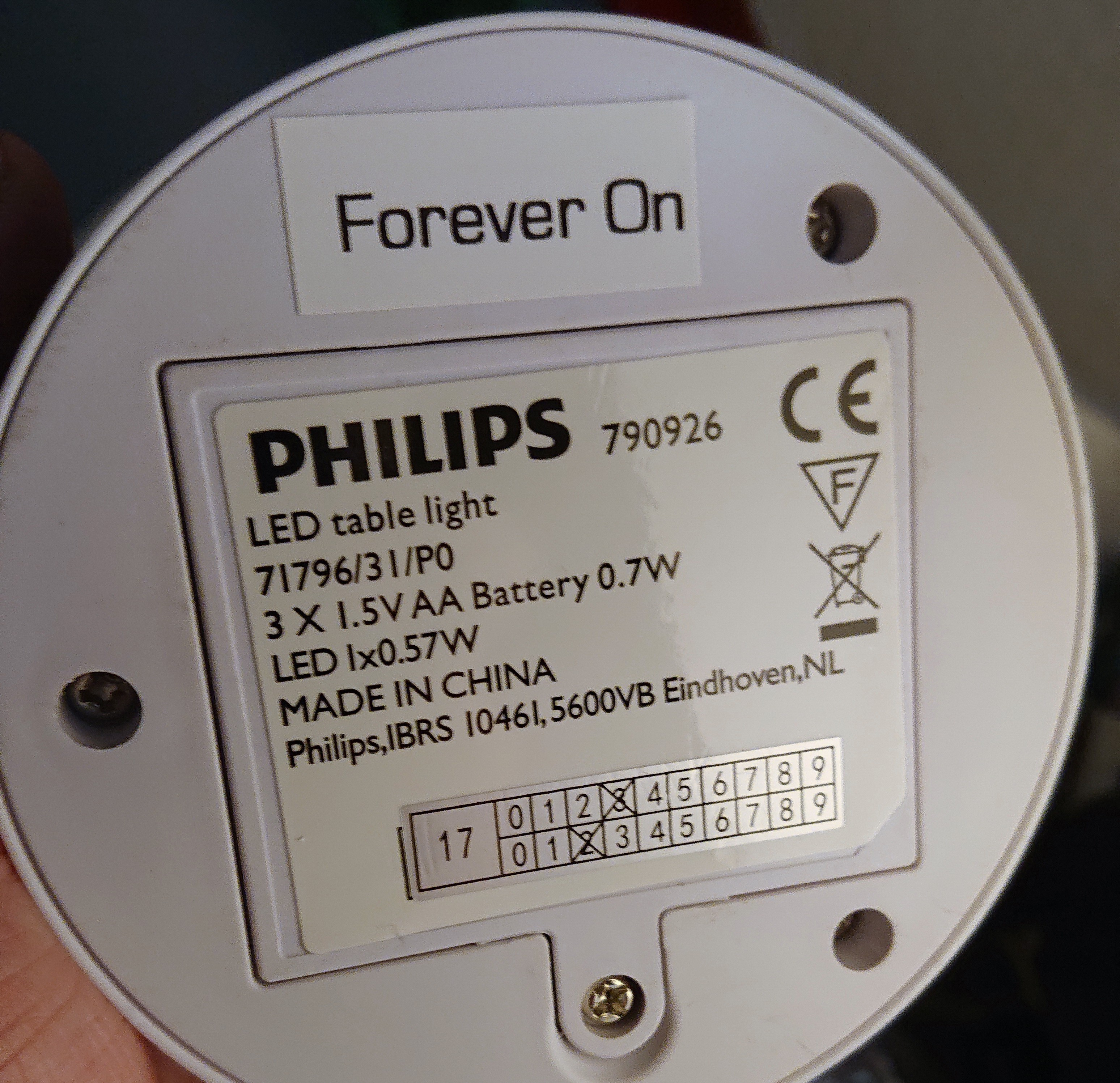
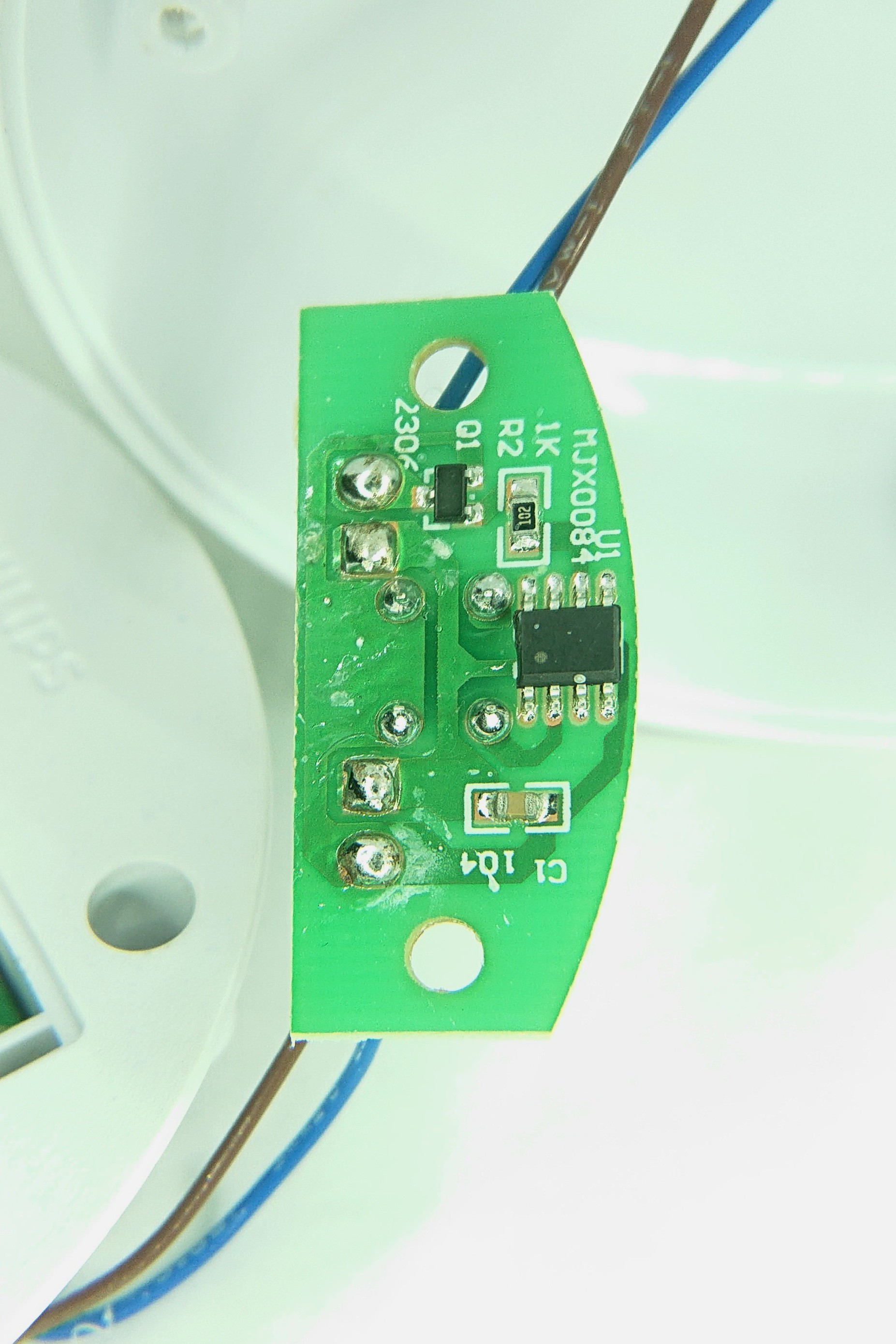
How to Hack a Table Lamp?
This project is about hacking a Table Lamp to extend or disable the integrated Auto-Shutoff.
 Stefan-Xp
Become a Hackaday.io member
Already have an account? Log in.
Just one more thing
To make the experience fit your profile, pick a username and tell us what interests you.
Pick an awesome username
hackaday.io/
Your profile's URL: hackaday.io/username. Max 25 alphanumeric characters.
Pick a few interests
Projects that share your interests
People that share your interests


 makeTVee
 Open Green Energy
 Adam Gulyas
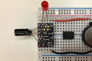
 Dillon Nichols
Haha, I also came across the same problem, but used a simpler solution: a switch.
I also noticed that the LED sinks ~130mA, so I looked for other alternative powering methods: I added a micro USB port to the side.
I wanted to maintain the battery operation so I came up with a circuit which automatically switches between USB and battery powered operation without sacrificing power drop on diodes and accidental charging from battery.
I did it on a test board with wire soldering, and unfortunately I have not taken any pictures.
I only have an LTSpice simulation screenshot in the case if anyone is interested in the solution:
https://i.imgur.com/3gC9Kxs.png