 Plasmode
In the first stage we'll build a very simple yet functioning Z80 computer with just 4 integrated circuits, plus resistors, capacitors and hardware. The bill of materials is included in the Files Section. In stage 1 the following items will be assembled:
| Part | Name | Source |
| U1 | Z84C0020PEG | Mouser 692-Z84C0020PEG |
| U2 | EPM7064SLC44 | UTSource |
| U3 | 128Kx8 Static RAM | Mouser 913-AS6C1008-55PCN |
| U4 | 22MHz oscillator | |
| R15 | 4.7K 8-pin SIP Bus | Jameco 1970367 |
| R1-4, R8-9, R16 | 4.7K, 1/8W | |
| C3-8 | 0.1uF bypass | |
| S1 | Push button SPST | Jameco 149948 |
| J1 | 2.1mm x 5.5mm Power Jack | Jameco 101178 |
| T34 | 3-pin header | |
| P2 | 1x6 right angle female header | |
| P3 | 2x5 header |
The pc board artwork is included in the FIles Section, so is the schematic of Z80SBC64 and the Altera EPM7064 programming file.
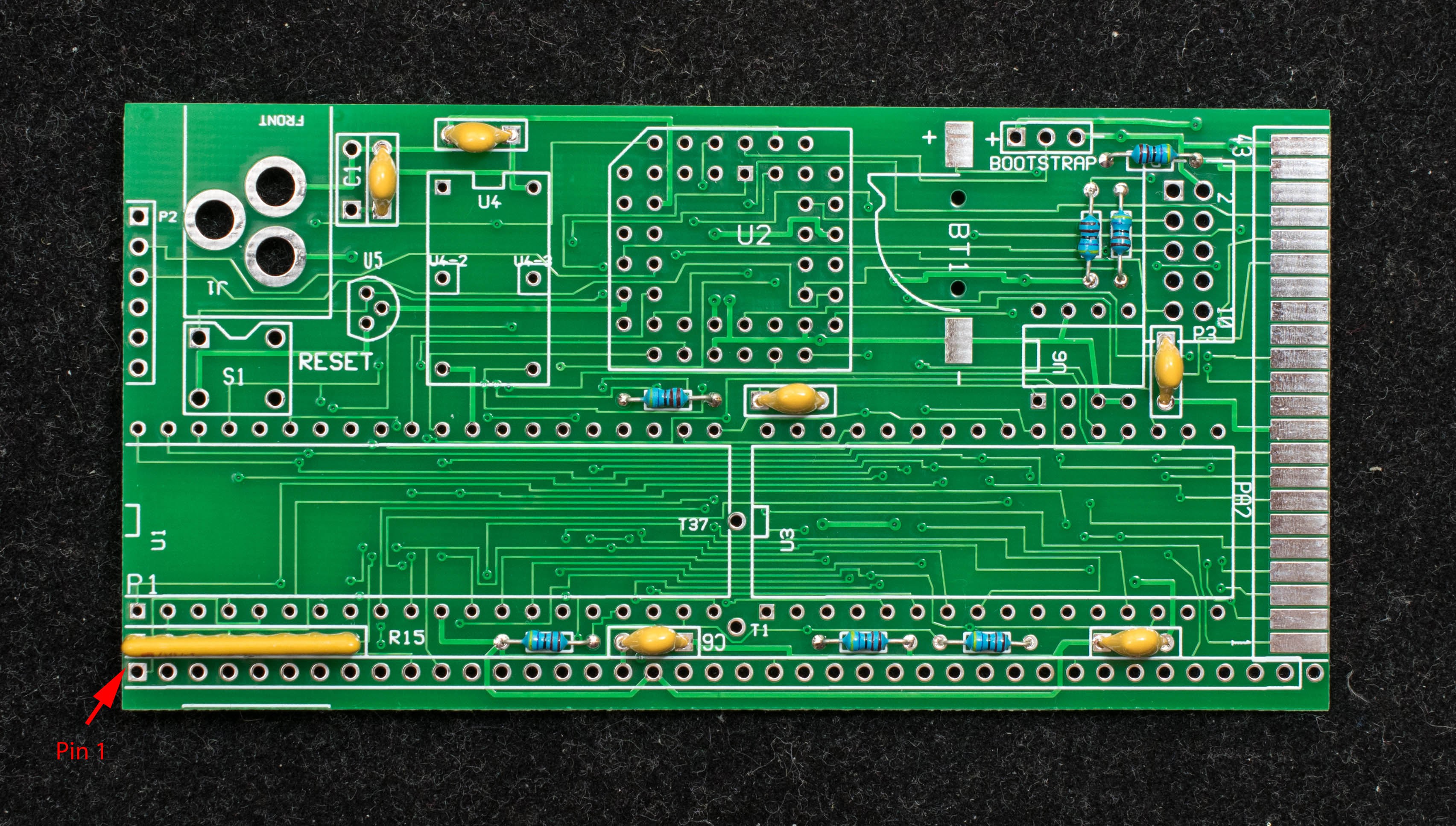
Here are step-by-step pictorial assembly guides for building a minimal Z80 computer. The order of assembly is based on the height of the components, the lowest components are soldered down first and the tallest last. In the first picture, all resistors (4.7K), bypass capacitor (0.1uF), and SIP resistor (4.7K BUS) are soldered down. Orientation of SIP resistor is important, pin 1 is marked with a black bar and oriented where the red arrow is pointed.
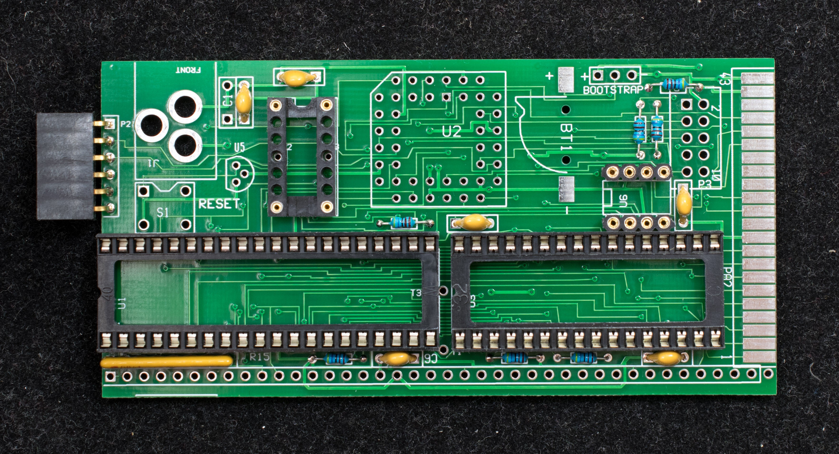
In the second picture, the IC sockets are installed as well as the 1x6 serial port header.
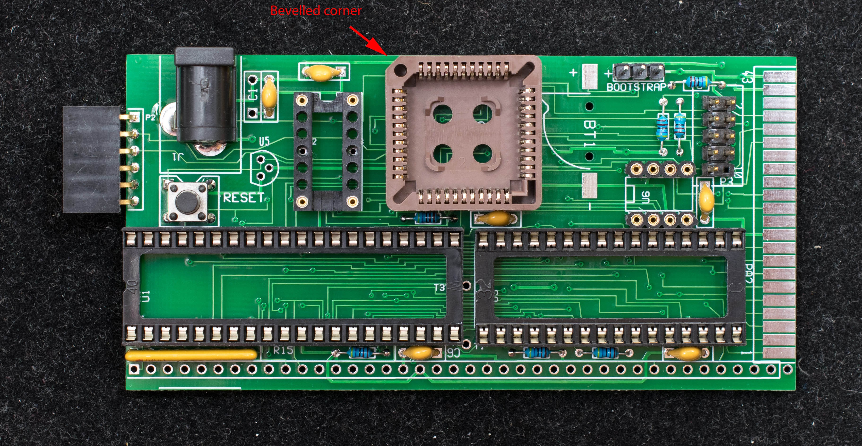
In the third picture, the PLCC socket is installed. The orientation of the socket is important, the beveled corner should be placed where the red arrow is pointed. 1x3 jumper block (T34), 2x5 programming header (P3), push button (S1), and 2.1mm x 5.5mm power jack (J1) are also installed.
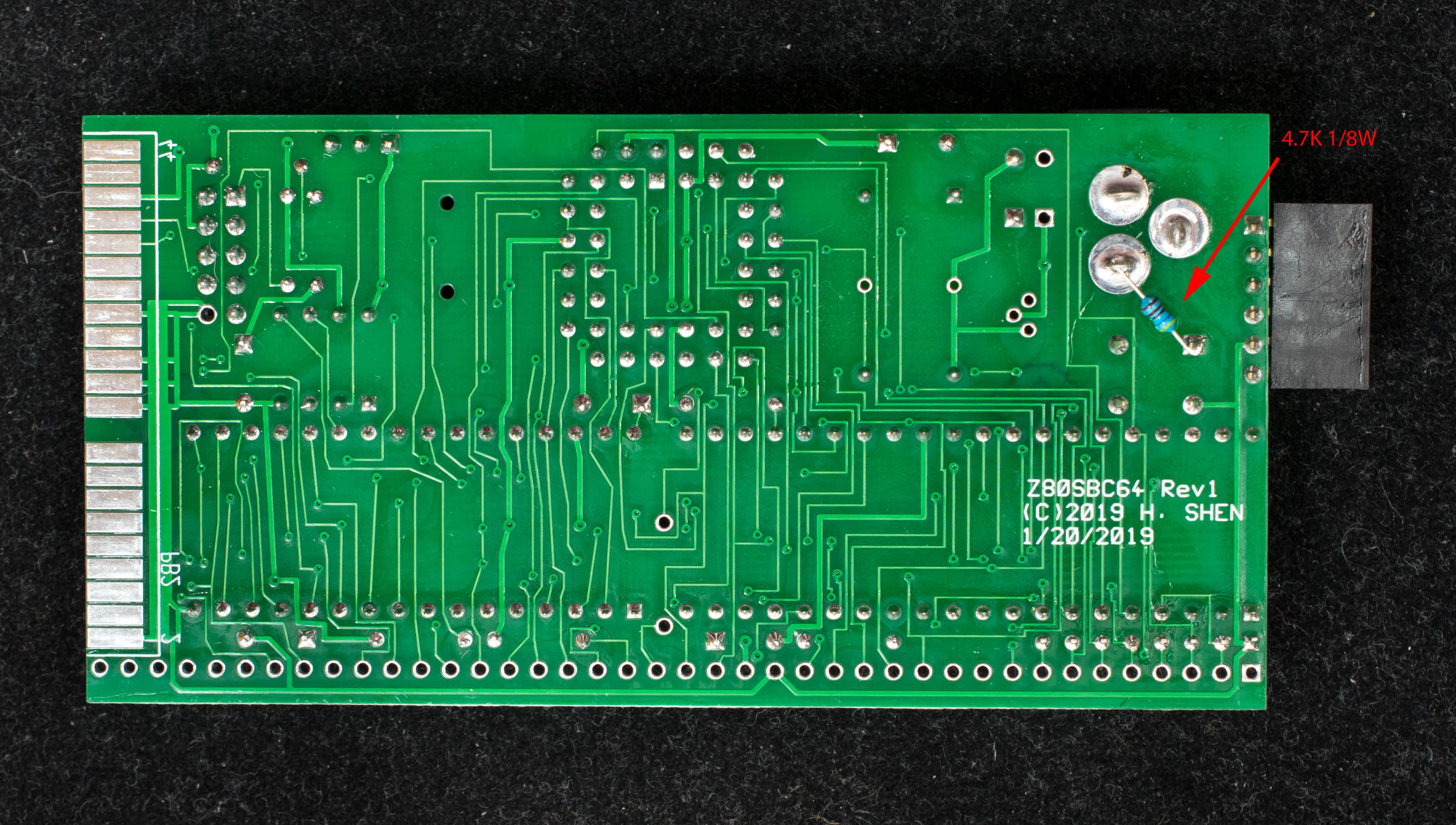
The fourth picture shows the solder side of the pc board. Because the reset supervisor, U5, is not yet installed, a 4.7K pull up resistor from nRESET to VCC is required to negate the nRESET signal. Please note, U5 may be optionally installed in this stage. If U5 is installed, then the pull-up resistor is not required.
The 1st stage assembly is now completed. The board should be cleaned with isopropyl alcohol and dried before installing components.
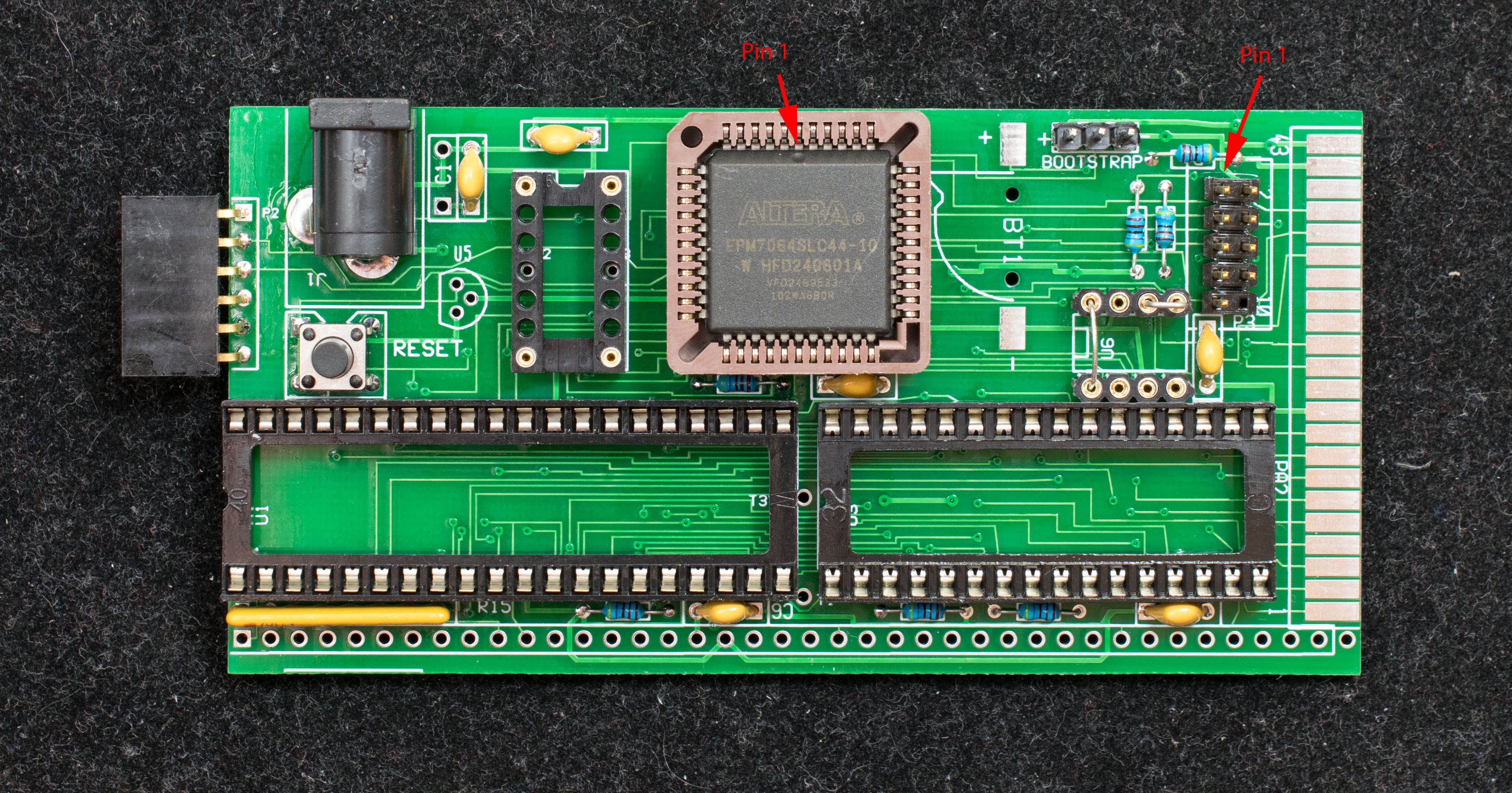
In the fifth picture the Altera EPM7064SLC44 is installed. Observe the orientation of the part, the beveled side with dimple in the middle must be aligned with the red arrow. Program the EPM7064 with USB Blaster, line up the pin 1 of USB Blaster cable (red strip) with the pin 1 of 2x5 header (pointed by a red arrow).
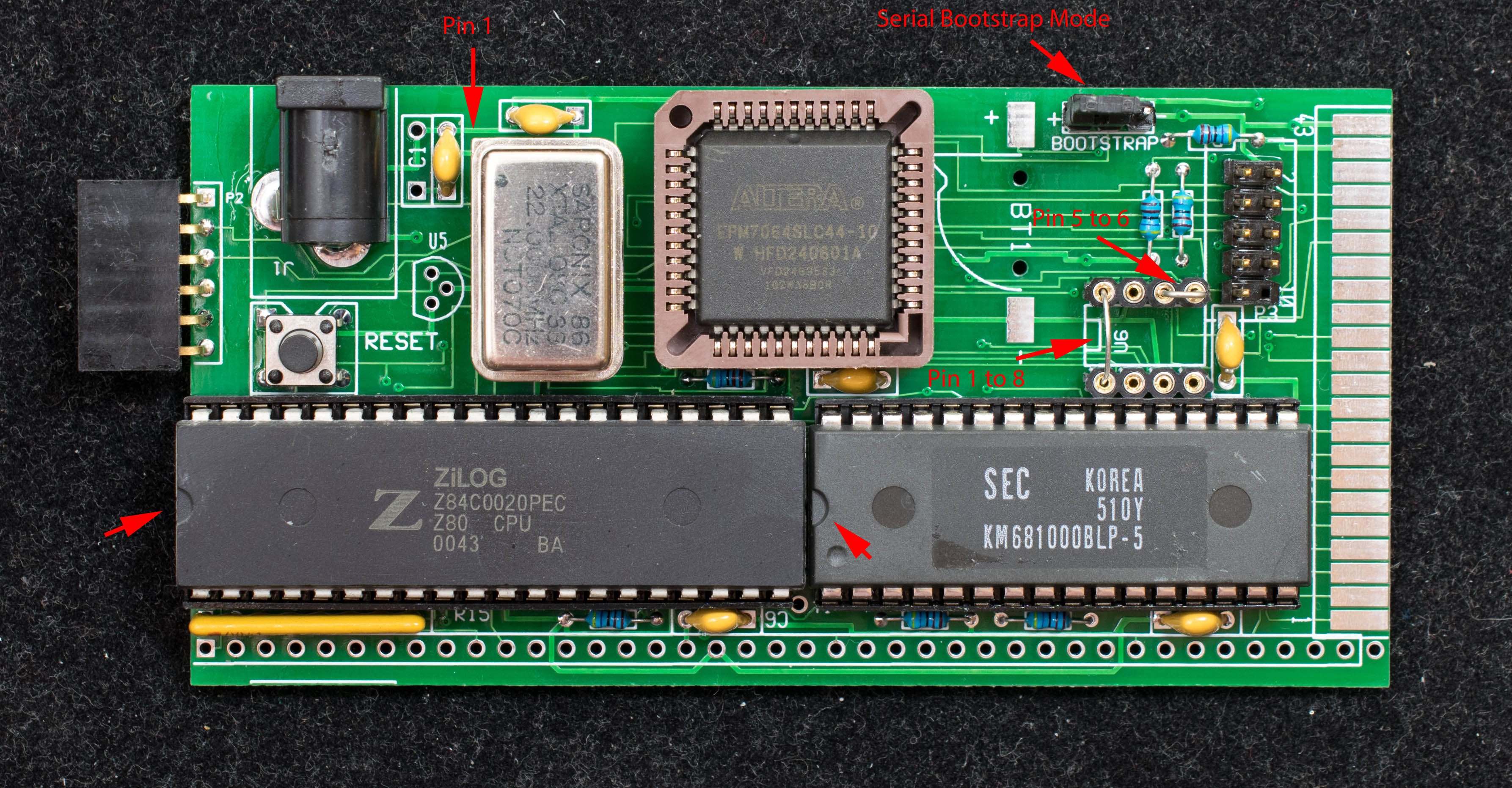
The last picture shows how the remaining integrated circuits are installed. Observe the orientation of the components. Also install the jumper to 'serial bootstrap' position as shown with a red arrow. Install two jumpers across pin1 & pin8 of U6 and across pin5 & pin6 of U6. The board is now populated and ready for power.
Discussions
Become a Hackaday.io Member
Create an account to leave a comment. Already have an account? Log In.