 M. Bindhammer
AR3 is a small modular humanoid robot of the LEGO EV3 form factor. The brain of AR3 is an ARDUINO MEGA 2560 with an according shield. Different to the LEGO BRICK parts of the electronics are exposed. The shield utilizes several 2.5mm pitch pin-and-socket connectors for analog and digital sensors and four 2.54 pitch pin-and-socket connectors for actuators (servos). The shield contains furthermore the low drop voltage regulator LM1084-5.0 with an output current of up to 5 A, an on/off switch, a monochrome 1.3" 128 x 64 OLED graphic display, a micro joystick, a SD card connector, a voltage monitor and a SMD piezo buzzer to generate sounds.
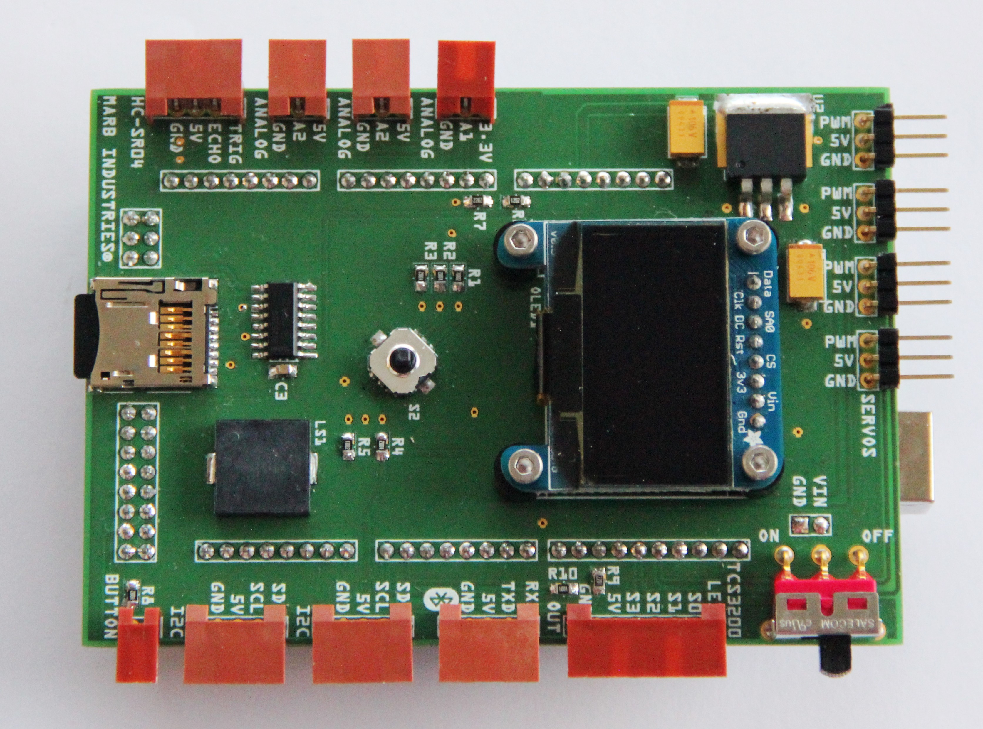
Fig. 1 Populated ARDUINO MEGA shield
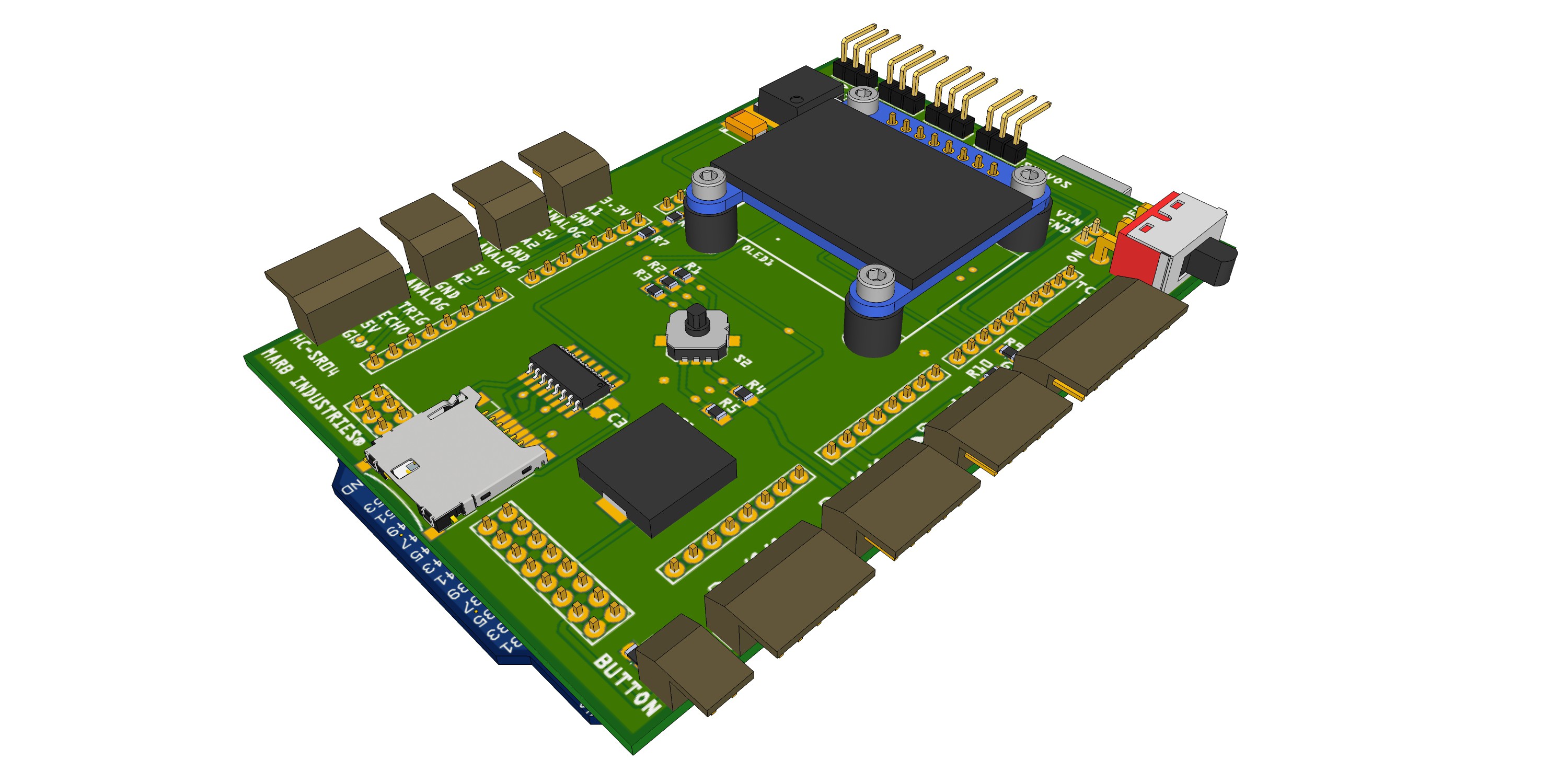
Fig. 2 CAD model of the shield
The head of the robot consists of 6 selective laser sintered, processed and different colored parts, printed by Shapeways and a HC-SR04 ultrasonic distance sensor as the "eyes" of the robot. The head features several additional mounting holes on the sides, top and bottom with a pitch of 6.5 mm and a diameter of 3 mm to attach additional actuators or sensors. Similar to LEGO I will keep this 6.5 mm pitch for mounting holes on all parts to make everything very modular and flexible. Different than LEGO I will use standard M3 screws and nuts to connect parts.
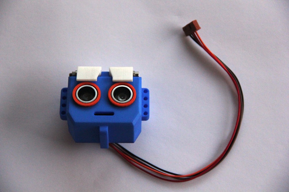
Fig. 3 Head of AR3
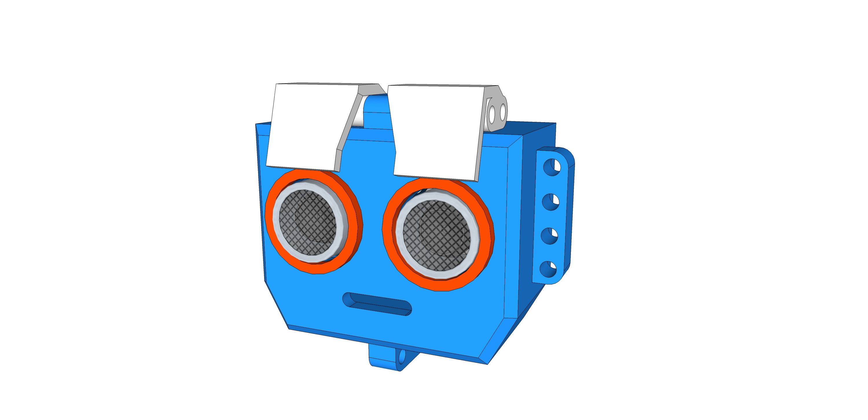
Fig. 4 CAD model of the head
Next figure shows the base of AR3. The robot is propelled by two continuous rotation servos (modified MG 995 servos, see tutorial here) in the back and two omni wheels in the front, where each wheel is supported by double bearings. The base consists of 5 selective laser sintered parts, two omni wheels from GTF, two servos, two tires from Makeblock, four Ø 4 mm bearings, two stainless steel axis with a dimension of 38 mm x Ø 4 mm, two metal servo horns and four Ø 4 set rings as well as some mounting material like screws and nuts.
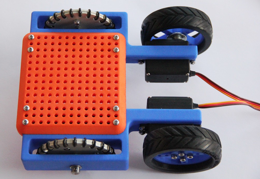
Fig. 5 Robot base
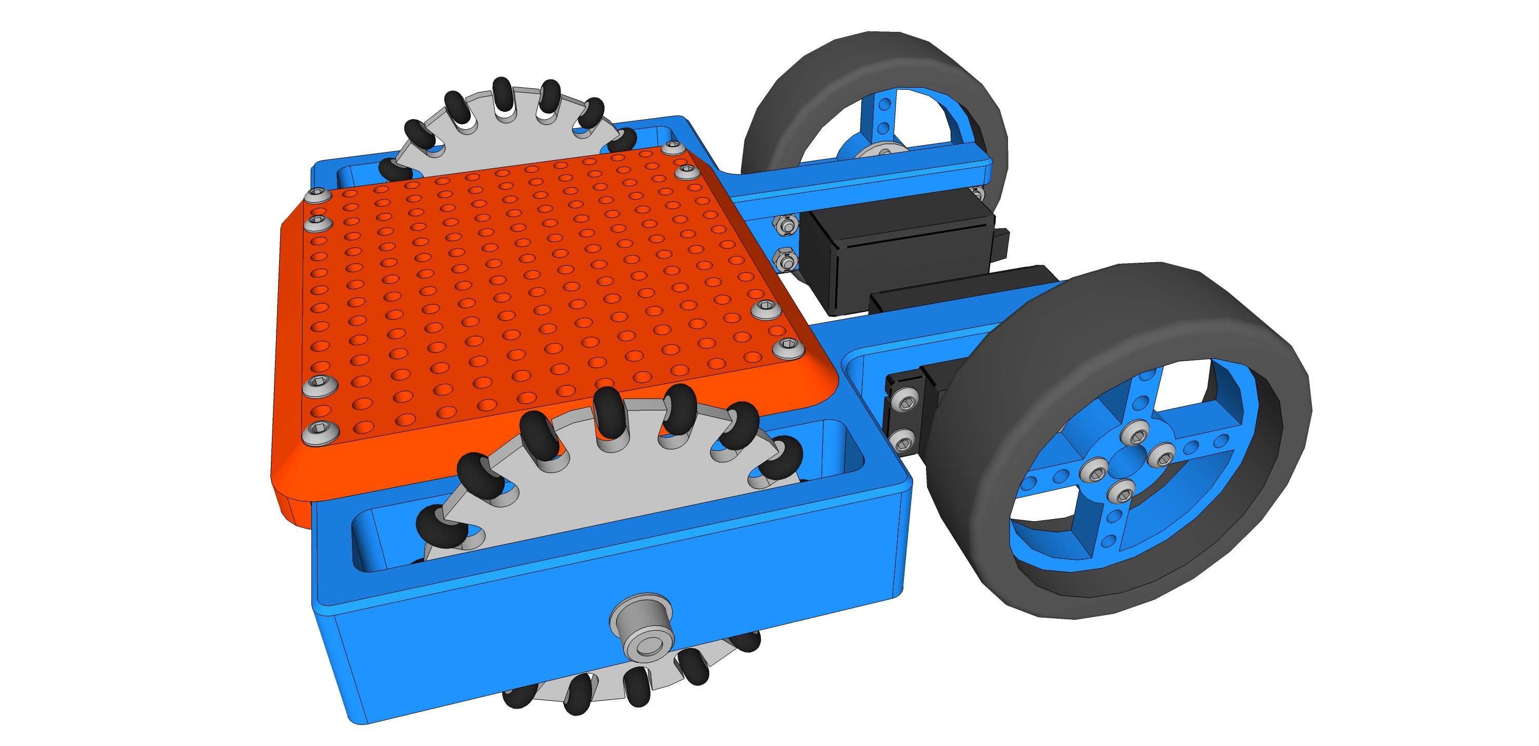
Fig. 6 CAD model of robot base
The TCS3200 color sensor is very suitable to introduce the k-nearest neighbors algorithm to students. I will explain the algorithm in a later log in detail. For now I just show the 3-D printed housing of the sensor. The two half-shell parts of the housing are just glued together using two-component epoxy, no screw bosses.
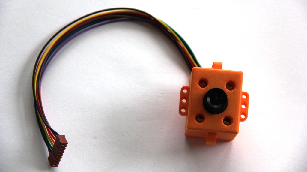
Fig. 7 TCS3200 color sensor with a collimator lens and four white LED's mounted in a 3-D printed shell
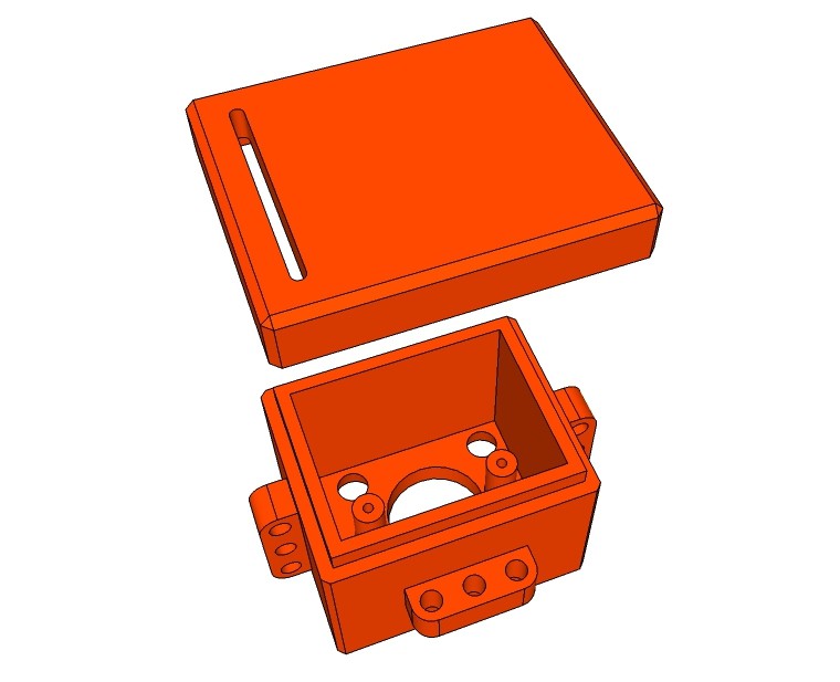
Fig. 8 CAD model of color sensor housing
I did some further work at the shield as well, 3-D printed an extension knob for the micro joystick.
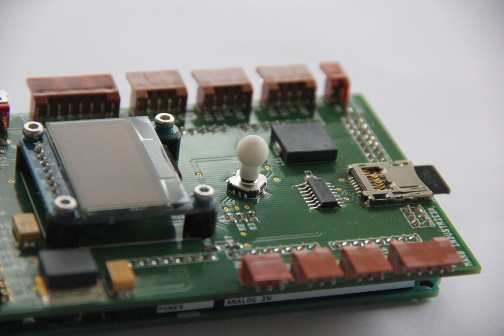
Fig. 9 Extension knob for the micro joystick
A tactile push button is most of the time the simplest digital sensor on a robot, but often quite useful, e.g. as a bumper sensor. The bumper sensor on AR3 consists of two half-shell parts, a plunger with a screw-on option and a momentary tactile push button switch, 12 x 12mm, 4 Pin DIP. Next figure reveals the construction. Again, the half-shell parts are just glued together after the inner components were assembled.
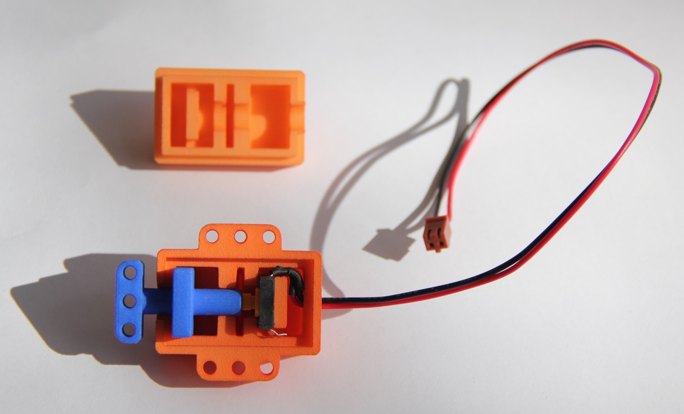
Fig. 10 Construction of the bumper sensor
A robot needs a gripper to grab things. Sub micro servos have in general the problem that their gears get stuck if you drive the axis mechanically and not by their own motors. The gear then breaks, no matter if plastic or metal, the motor stalls and the servo gets damaged within a few seconds. They also have too less torque to be of any use for a gripper. The HITEC 85 MG has a slightly bigger form factor, a ball bearing, a torque of 30 Ncm, a metal gear and no problems to drive its axis mechanically when its motor is powered off, so I designed the AR3's gripper around this high quality servo, also pricey. The gripper therefore got a little disproportionate, like a human being wearing a boxing glove, but that's still OK. Next figure shows the gripper. Two 3-D printed parts, all guides have ball bearings and are therefore resistant to wear, metal servo horn is made out of aluminum and all mounting materials (screws and nuts) are made of stainless steel.

Fig. 11 Gripper of the robot. Can grab large and small things
In a further step I 3-D printed the housing for the ARDUINO MEGA and the shield. LEGO calls it the "brick". Equal to the brick it has connectors for the legs and arms and the head. A purchasable common battery back is assembled on its back, containing six AA-batteries, alkaline 1.5 V batteries or rechargeable 1.2 V batteries, both work. I replaced the original flimsy wires of the battery box by high quality 22 AWG silicone wires as the robot will draw more current as these flimsy wires can provide.
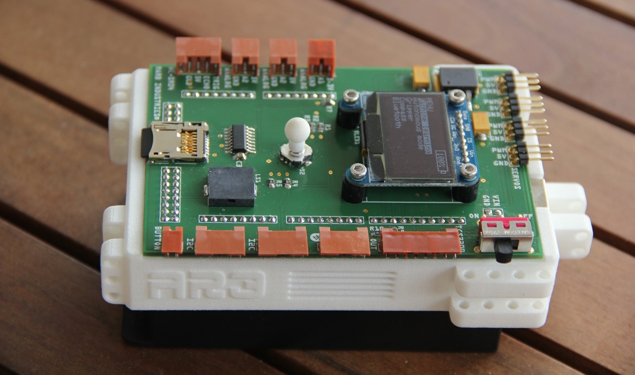
Fig. 12 3-D printed housing for the ARDUINO MEGA and the shield
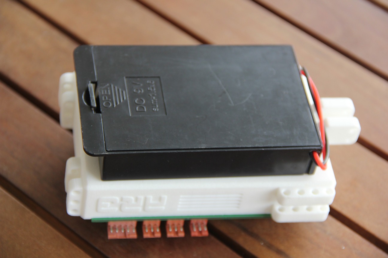
Fig. 13 Mounted battery box
As the rest of the 3-D printed parts arrived as well, I assembled the legs and the upper arms.
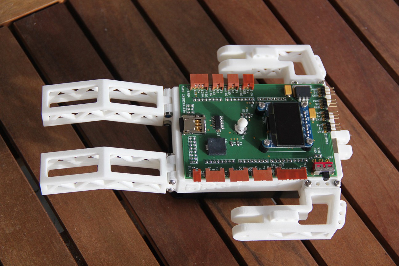
Fig. 14 Legs and upper arms mounted
Furthermore I assembled the forearms and already printed and finished actuator and sensor parts of AR3.
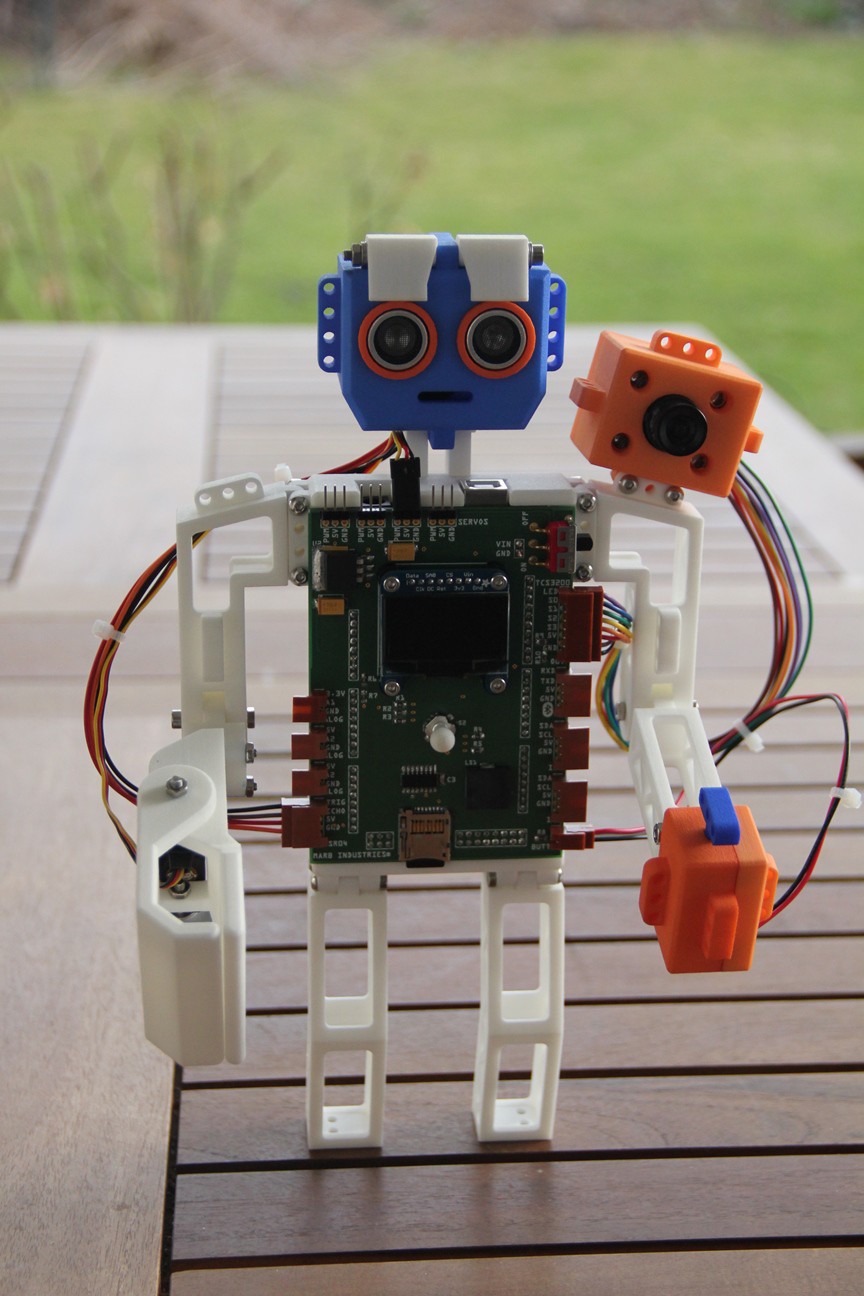
You will notice that the USB plug cannot be inserted at the current position of the head to the ARDUINO MEGA. So I mounted the head using only one single screw to be able to turn the head 90 degrees to the back and insert the USB plug to program the robot. And then, in a for now last step, I added the base.

Fig. 15 Base added

Fig. 16 CAD at the latest stage, some minor changes made
Mechanically the robot is now nearly finished, just need to add a Bluetooth and compass module for the basic set.