 Bud Bennett
While I'm waiting for the delivery of the VL53L0X sensor boards from AliExpress, I thought I'd take a whack at understanding the PCB requirements for a first prototype of the halo. The Arduino Feather M0 Express that I got from Adafruit has been working flawlessly. The current drain of the Feather coupled with a VL53L0X sensor board was about 40mA, <20mA for just the Feather, so I thought it worthwhile to explore using the Feather with some custom sensor PCBs as a simple solution (since I only need to make one of these systems).
My first attempt was to just place the AliExpress PCBs into a motherboard that attaches to the Arduino Feather that I ordered from Adafruit. It was huge. The board would be at least 3 inches in width, which might cause Lucy some problems with the fit. I can do better. Therefore, the AliExpress boards will only be used for prototype purposes -- whatever physical arrangement works to prove the concept. I'm planning on using six-pin dupont connectors and gluing the AliExpress boards to a substrate to get the first prototype working. (Or maybe just desoldering the sensors and migrating them to new PCBs.)
Going My Own Way:
By abandoning the AliExpress boards I need to make two sets of PCBs: a daughterboard to contain each VL53L0X sensor and any support circuitry, and a motherboard that attaches to the Feather M0 Express.
After examining the space requirements of a 0.1" header vs. a 0.05" header, I decided to use the smaller headers to save a lot of space. I ordered a slew of 1.27mm pitch right angle male headers from eBay. Each VL53L0X sensor daughter board only needed the sensor and two capacitors:
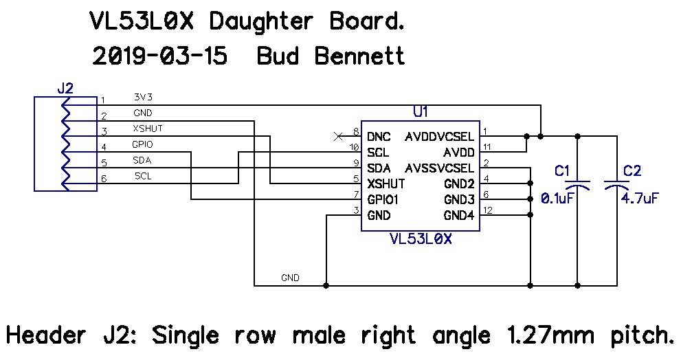
I also decided to use the Arduino 3V3 regulated power supply. This saved many resistors, level translator transistors, and a voltage regulator -- for each daughterboard and the motherboard. The VL53L0X data sheet claims that the part will function without issues with a 3.3V power supply. So be it. The preliminary daughterboard dimensions are 0.35" x 0.4". Pretty small, compared to the AliExpress boards (but not cheaper). The daughterboard attaches to the mother board with 6-pin right-angle headers.
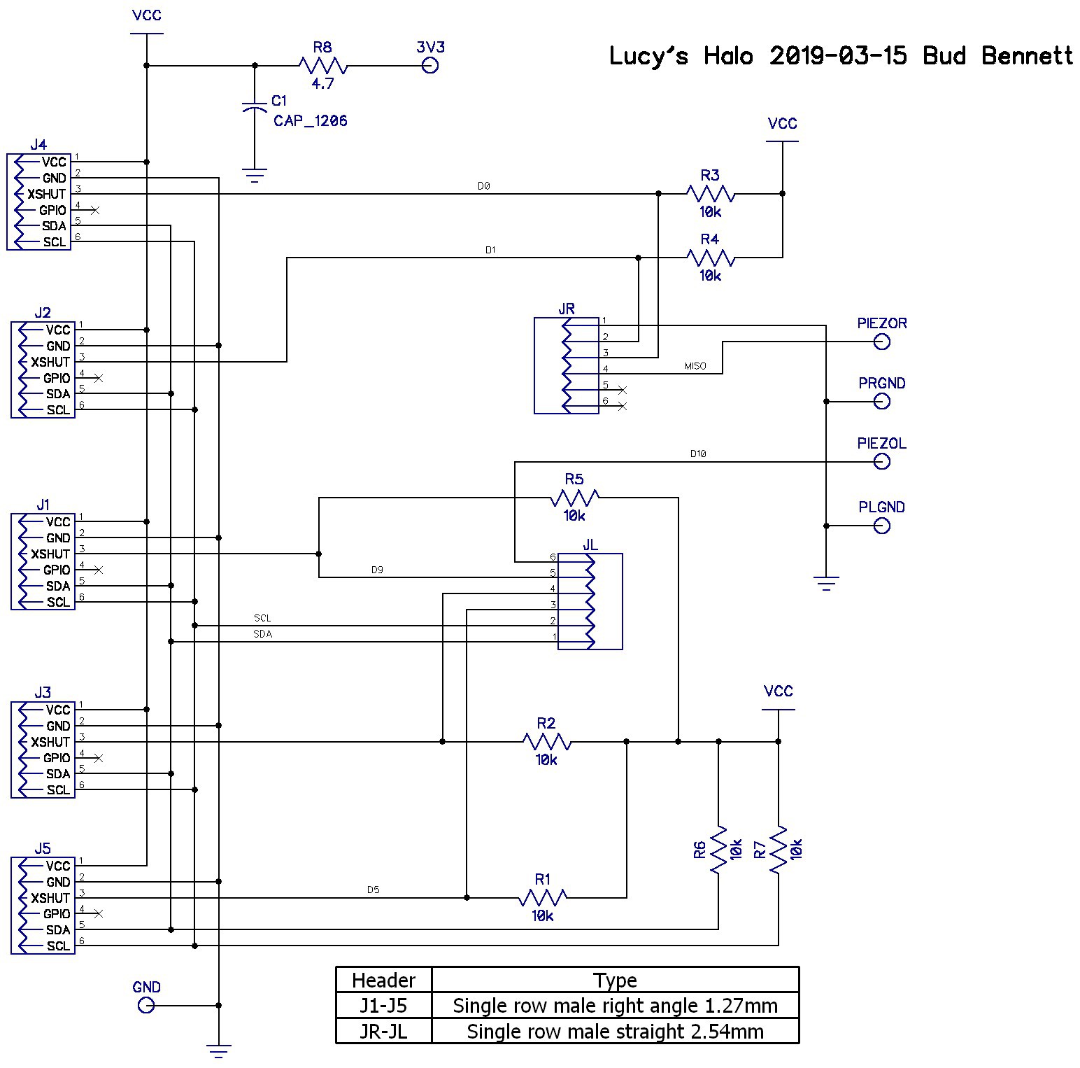
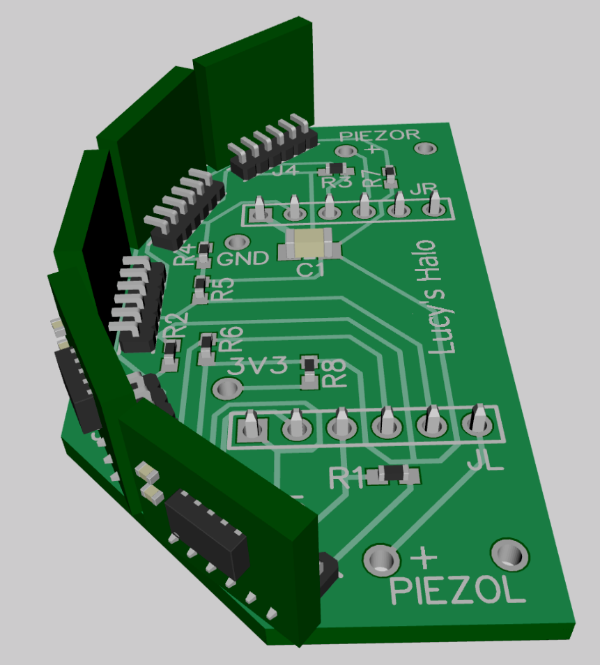
I'm not entirely convinced that all those resistors are necessary. There are placeholders for R8 and C1 -- CYA components. A lot of the pull-up resistors (R1-R5) may be depopulated after the first prototype. After creating the daughterboards I placed them into the motherboard PCB layout to see how big it would be and what challenges popped up. After a few iterations, I settled on the layout below.
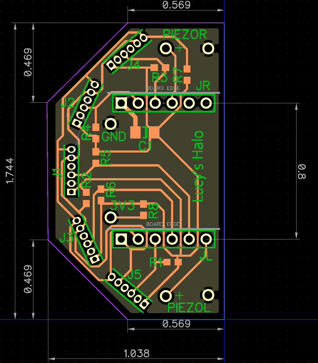
The motherboard plugs into the Arduino using the 6-pin headers spaced 0.8" apart. I also need the Arduino's 3.3V regulated output, which is not available in the first six pins of the header, but Adafruit did provide it as part of a small breadboard area on the Feather M0 Express. Lastly, the two piezo speakers are mounted at the left/right rear of the motherboard -- pretty close to Lucy's ears. (Here's where a couple of resistors in series with the piezo speakers might have been warranted.)
I tested the assignment of the GPIO with the motherboard header pins -- no issues. Both the daughter boards and mother boards have been ordered. Awaiting delivery of PCBs fro JLCPCB -- check back in one week.
Discussions
Become a Hackaday.io Member
Create an account to leave a comment. Already have an account? Log In.
Great progress.
Are you sure? yes | no
Yes, but don't confuse motion with progress (Albert Einstein). I edited this log to include the latest developments, rather than making a new log. New stuff was just an iteration on the old stuff.
Are you sure? yes | no
We have a saying here that translates to "standing still, is going back" (i.e. doing nothing, is like moving backwards).
Best of luck to you and Lucy.
Are you sure? yes | no