 Connor Yamada
My design goals for this project were simple:
- Long battery life
- Wireless communication
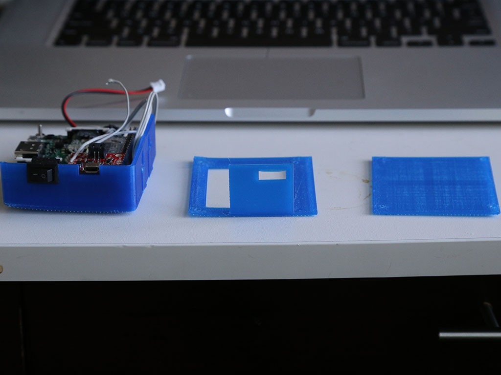
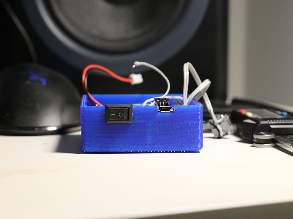
- Simple, durable enclosure
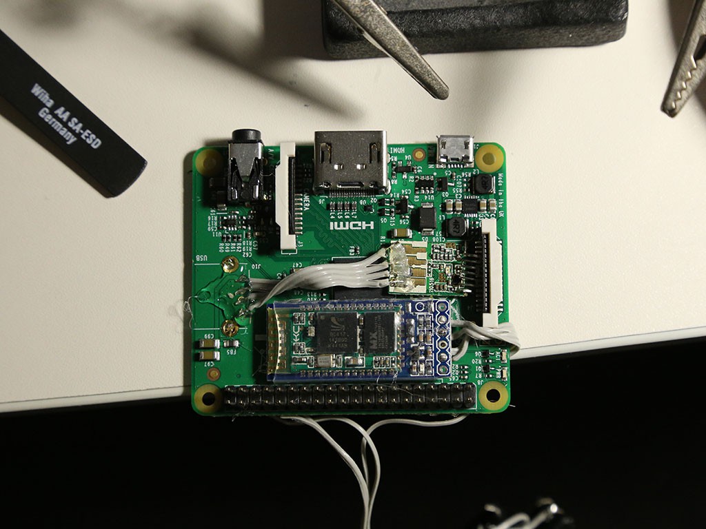
The first goal meant having a large battery. The hour to hour and a half battery life of the GoPro wouldn’t cut it for longer, multi-hour rides. The second meant having both Bluetooth and WiFi so that additional hardware wasn’t needed to interface with the camera. The last goal also played a big role in determining the first two. While designing holes/slots to make every port available outside the case would have made things more convenient, it would also have reduced the structural integrity and water/dust resistance.
Please note that the choppy video in the clips is due to rendering issues. The quality of the video is the same as every other Raspberry Pi camera board.
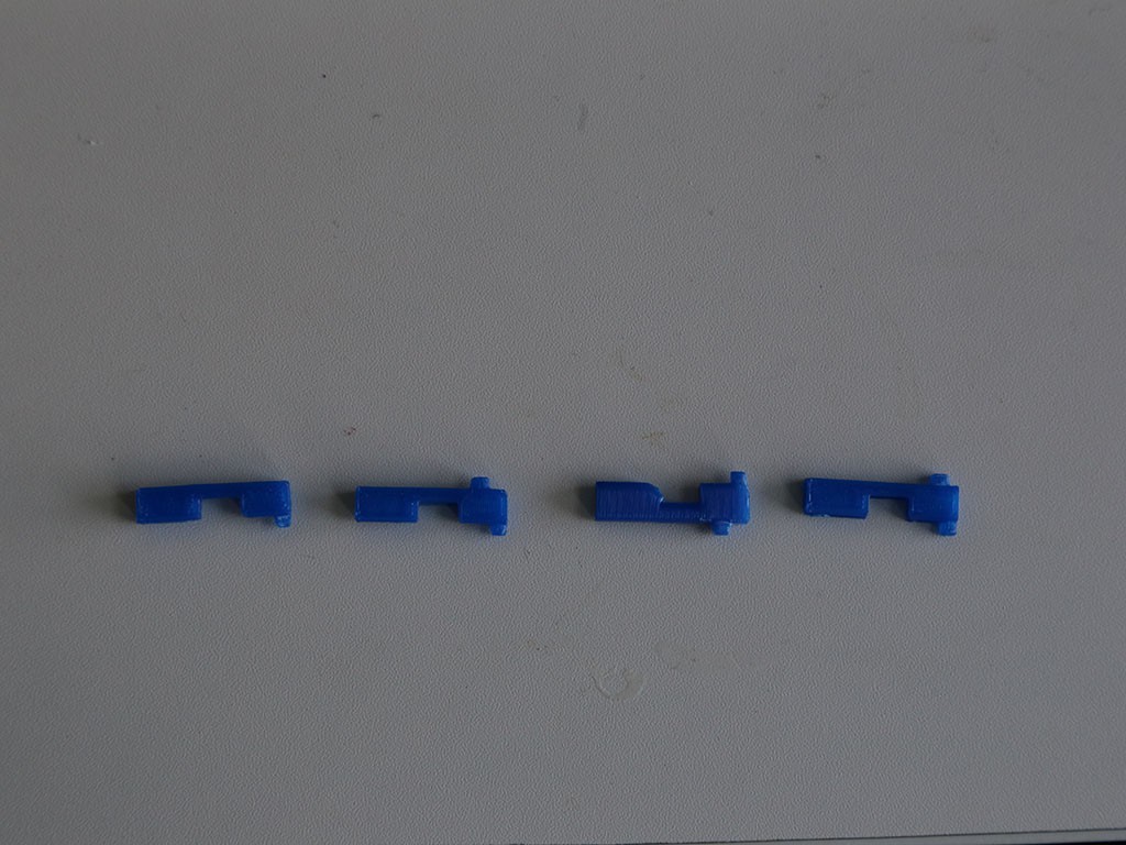
 More test prints.
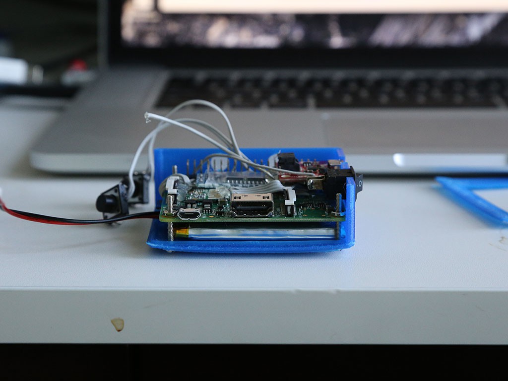


 Daniel
 peter jansen
 Arducam
 nick.r.brewer
Hi Rajendra,
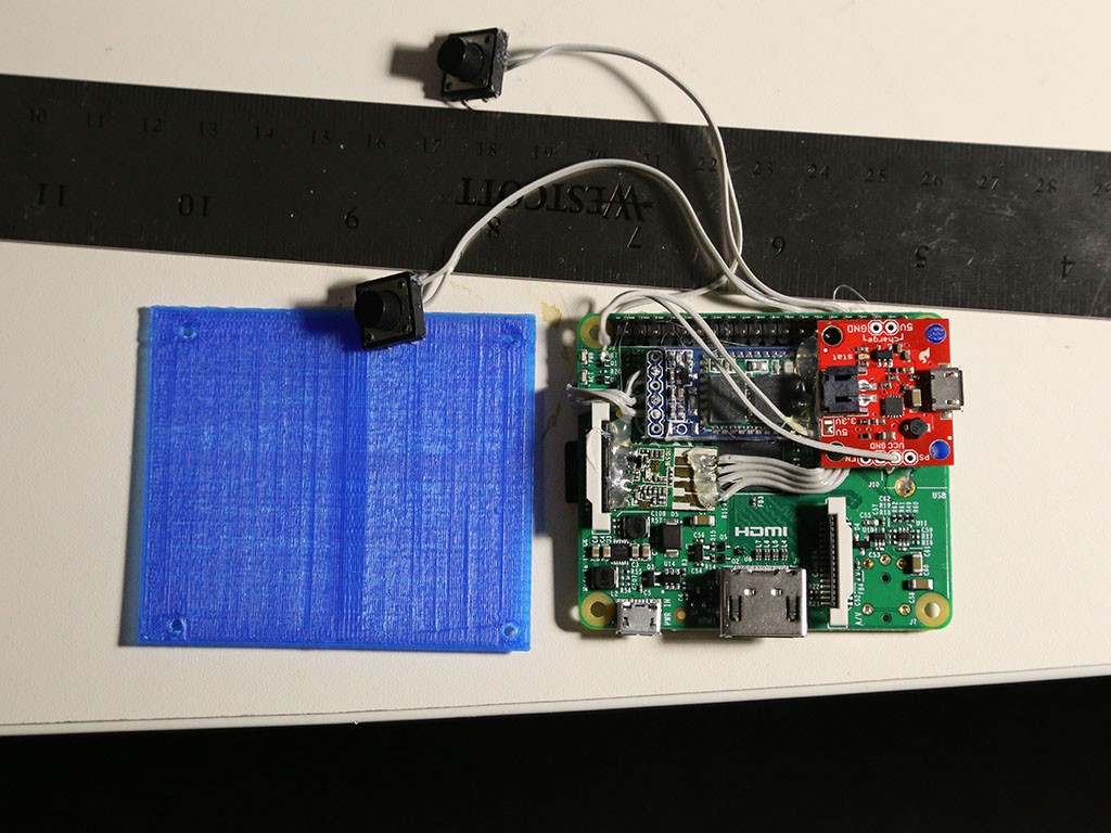
The buttons are used to start and stop video recording, in addition to turning the camera on and off (I should have clarified this in the description but you can see the code here:
https://github.com/cyamada/picam/blob/master/picamcorder.py)
These can of course be reprogrammed to better suit your needs (still photos, enable/disable wireless, remote timer ect).