 Plasmode
Once the CPLD is checked out and working, we are ready for stage 2. Stage 2 is to assemble a bare minimum 68030 computer that contains 68030, RAM, CPLD and an oscillator.
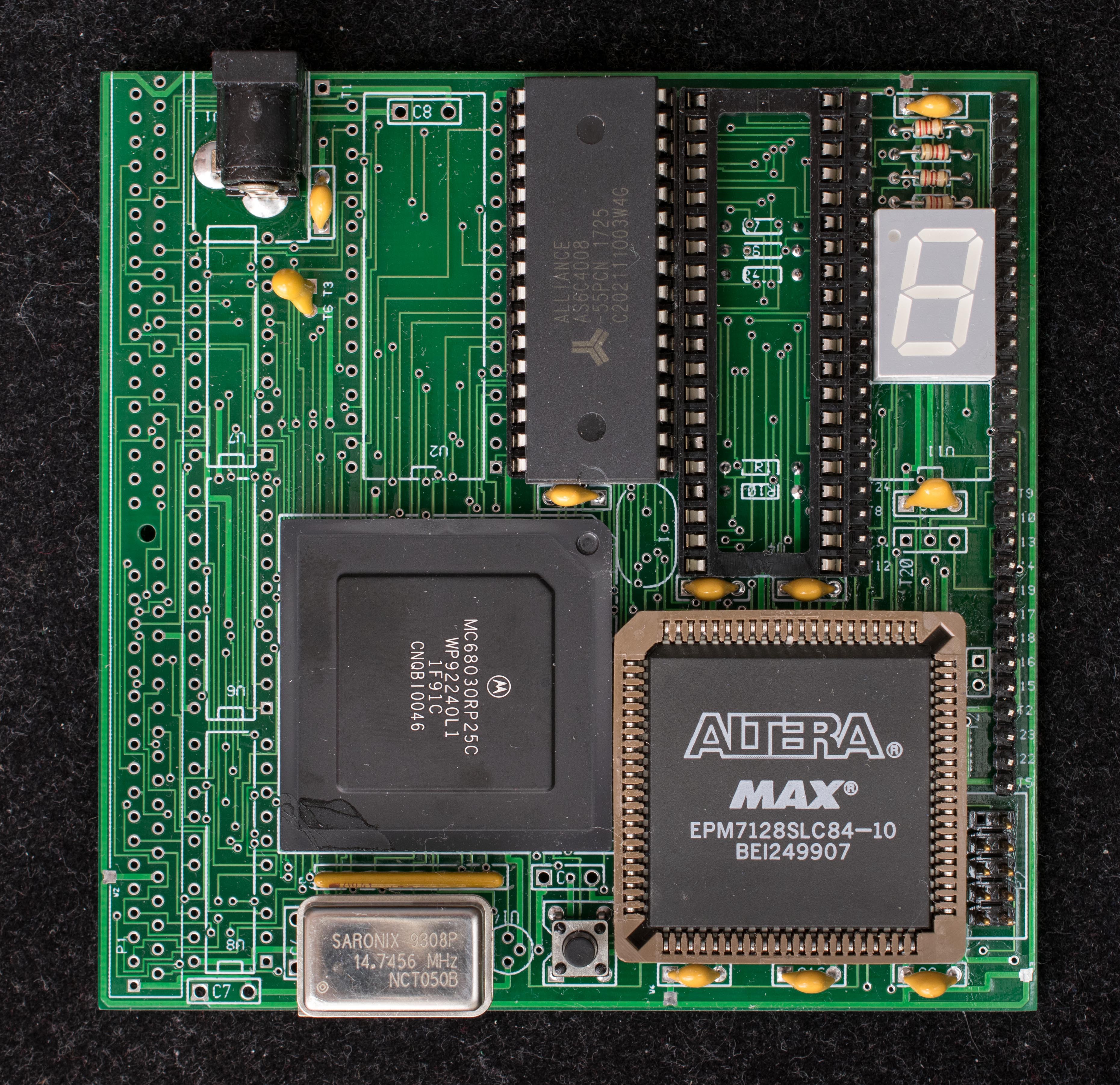
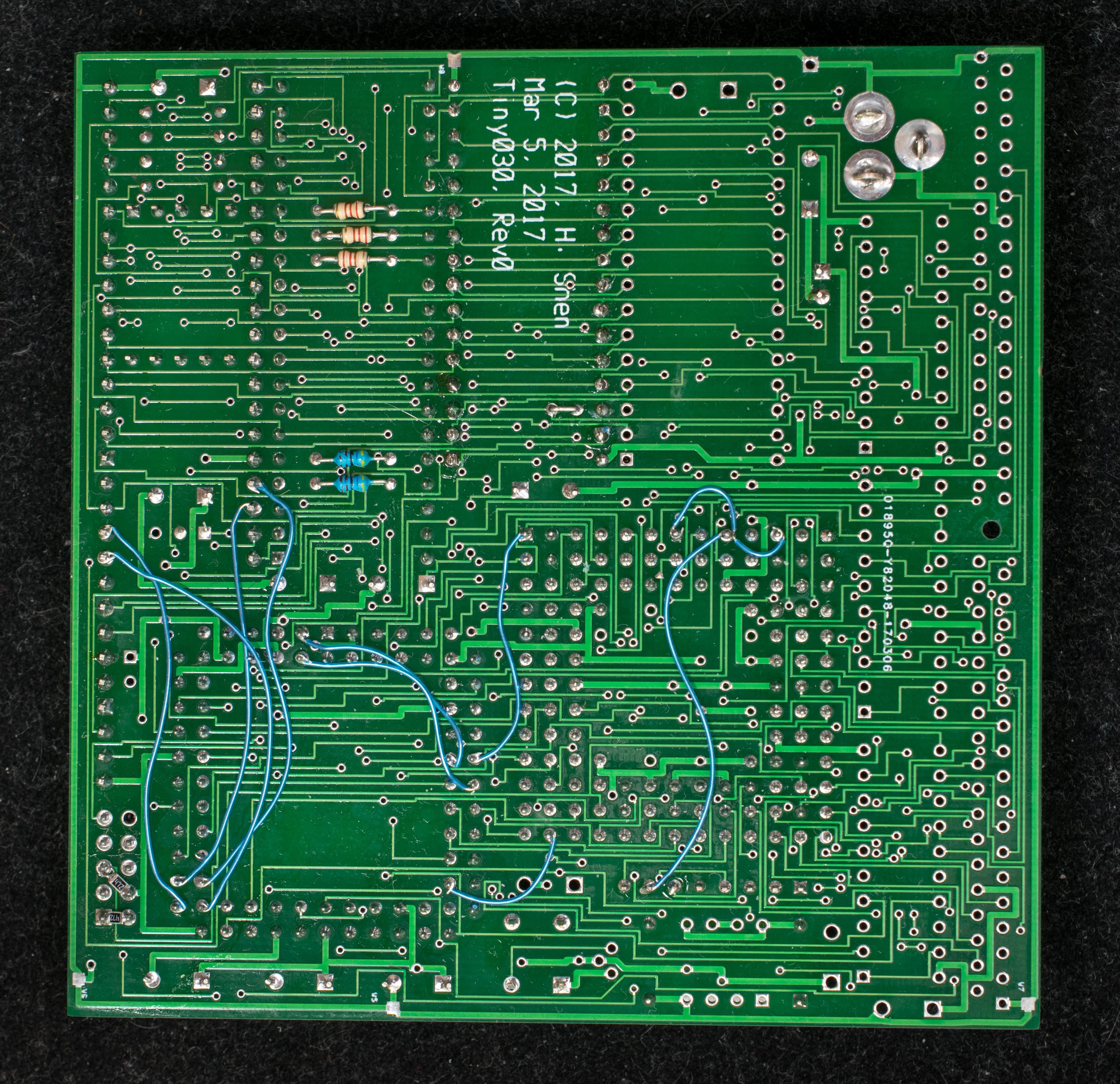
There are a number of manual wires need to be done at the back of the board:
- Pull up nCIIN, nCBACK, nSTERM to pin 7 of SIP resistor pack R9
- Connect Address 7 from pin 31 of CPLD to pin B13 of 68030
- Cut the trace between pin A1 of 68030 to pin C3. This isolates nBUSREQ from nBGACK of 68030
- Connect pin 20 of CPLD to nBUSREQ (pin A1) of 68030
- Connect pin 21 of CPLD to pin 83 (nAS) of CPLD
- Connect pin 22 of CPLD to pin 84(R/W) of CPLD
- Connect pin 54 of CPLD to test point T13
- Connect pin 55 of CPLD to test point T14
- Connect pin 56 of CPLD to test point T8
- Connect pin 57 of CPLD to test point T24
 A prototype board with additional manual wires need to plug into the expansion headers, U11 to enable the serial bootstrap function
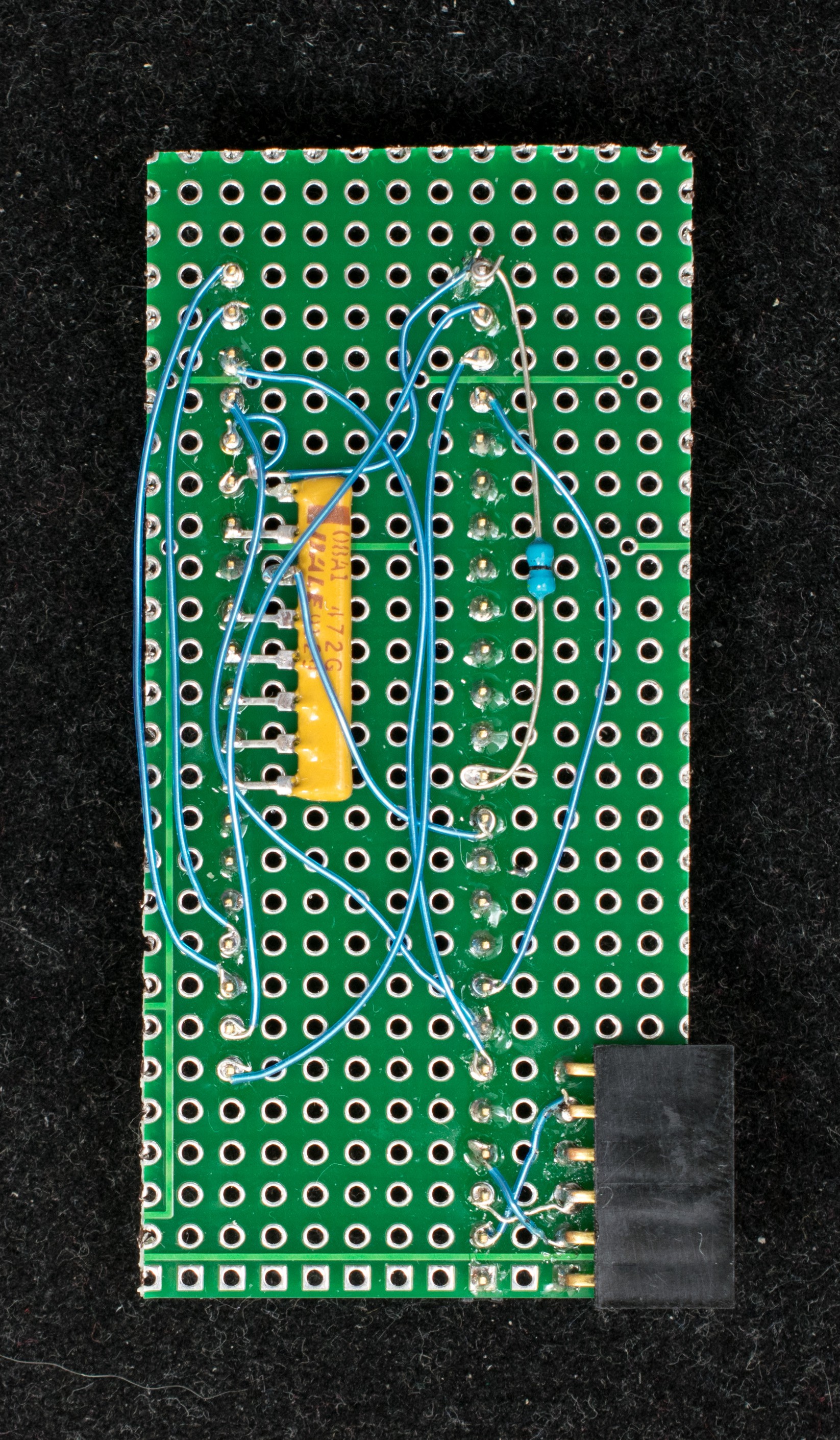
Here is the board that's ready to power up.
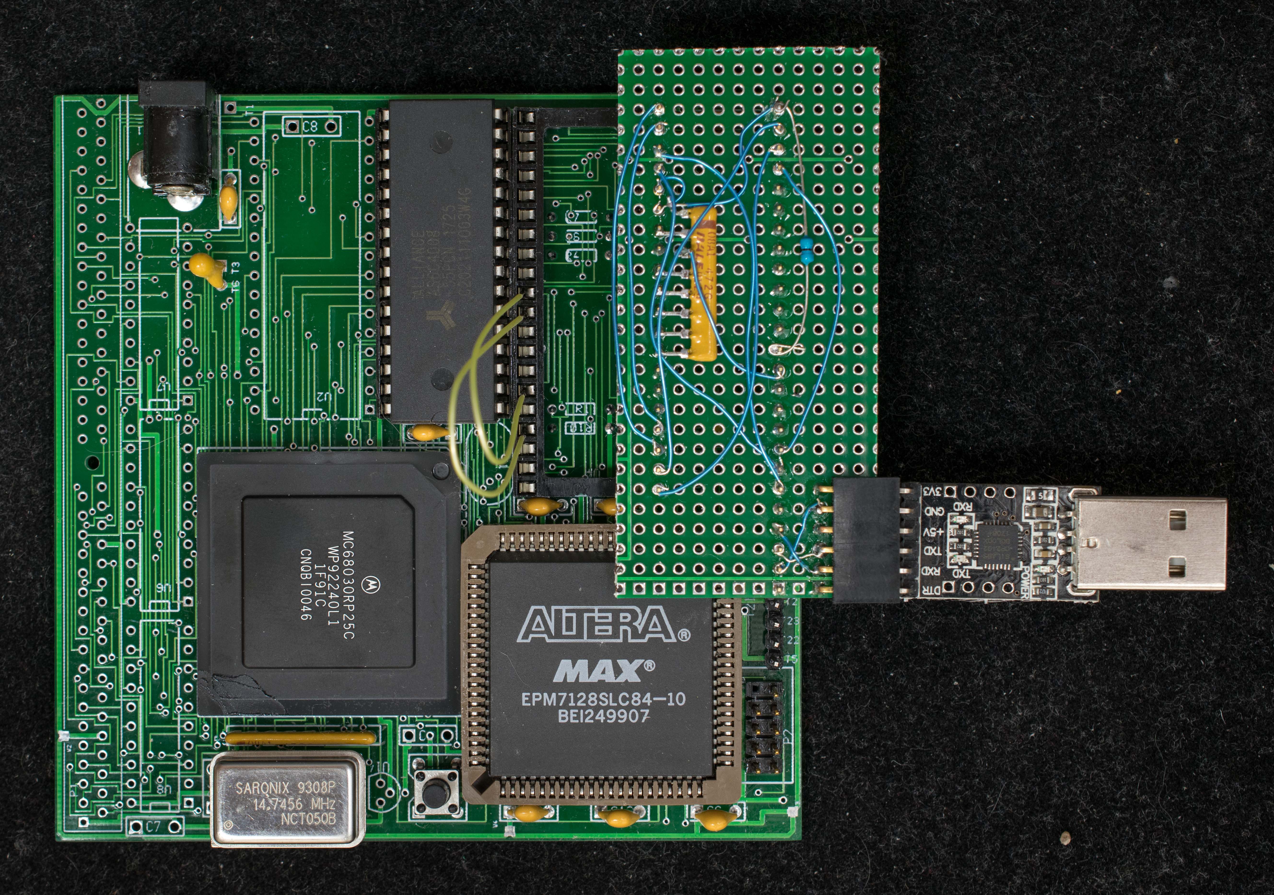
The USB-to-serial adapter connects to terminal emulation (I use TeraTerm) program at 115200-N-8-1. Programmed in the CPLD is a simple serial port and DMA circuitry controlled by a state machine. At power up the CPLD state machine generates a bus request to 68030, then the state machine takes control of the 68030 address and data bus and waits for serial data input. Every data received is DMA to memory starting from location 0x0 until 255 bytes of data is received. At that point the state machine relinquishes the bus and 68030 starts program execution from 0x0 like a normal power-on reset operation. The small 255-byte program is typically a simple file loader that load more sophisticated application programs. This is the mechanism by which the minimal 68030 computer can be loaded with diagnostic software to further test the board and to develop application software.
A reasonable question can be ask whether this stage is consider a "baby step" due to the many manual wires where mistakes can easily be made. That's a good point for this particular version of pc board, but I also want to use this experience to develop a revised pc board where stage 2 can be done without too much manual wiring.
This is the CPLD file for stage 2 68030 computer
Discussions
Become a Hackaday.io Member
Create an account to leave a comment. Already have an account? Log In.