 Matthew James Bellafaire
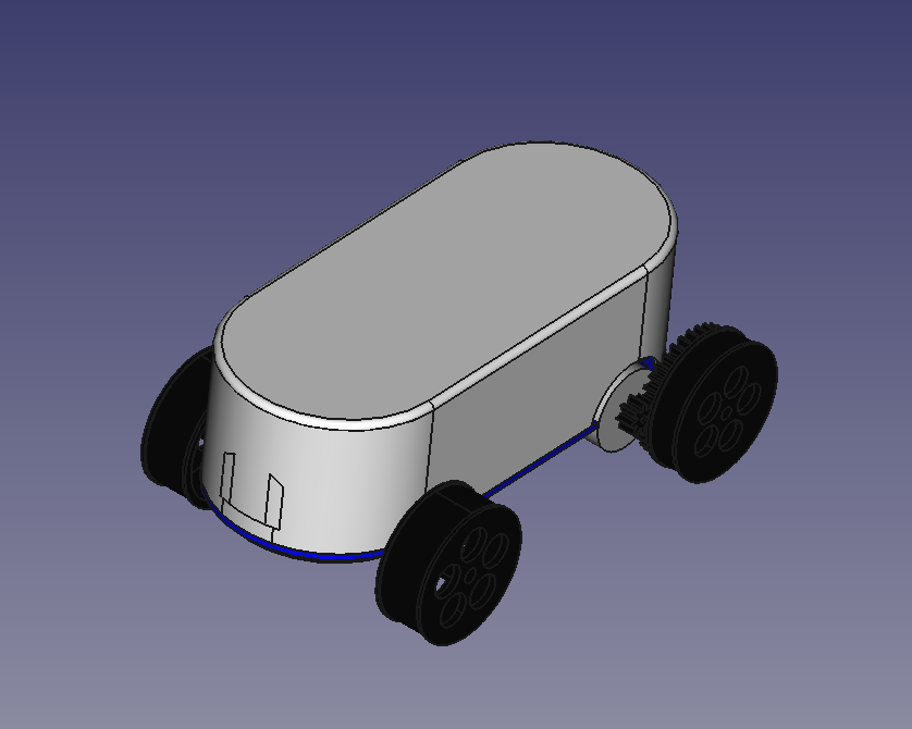
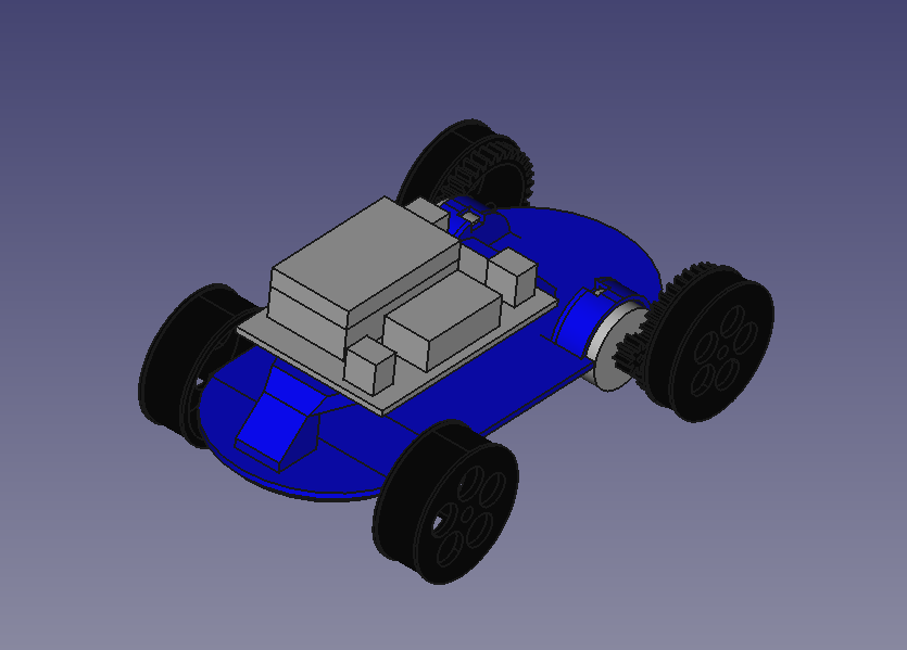
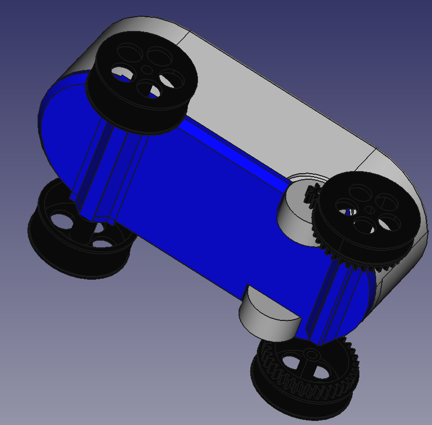
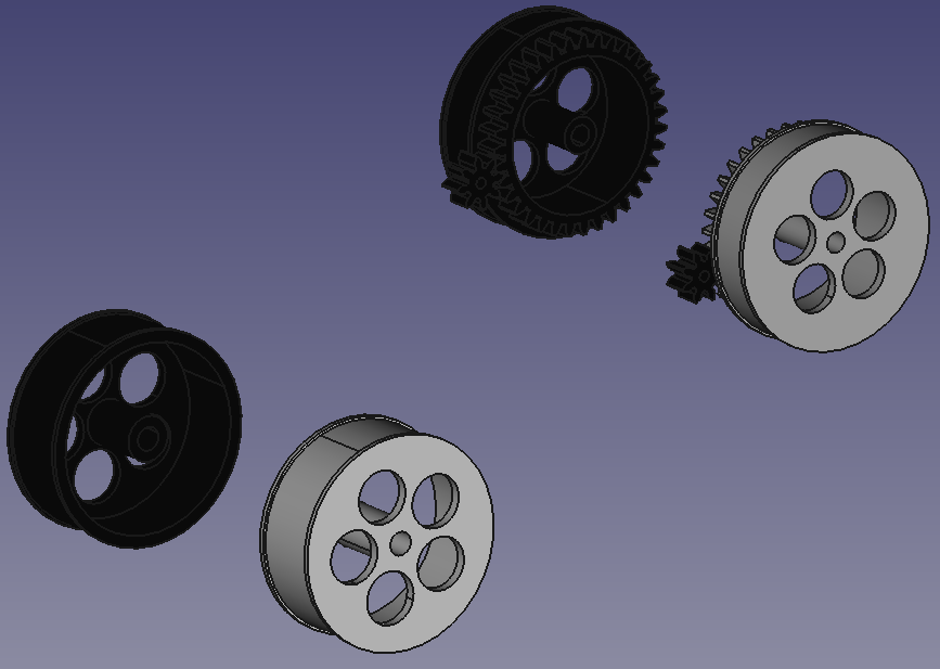
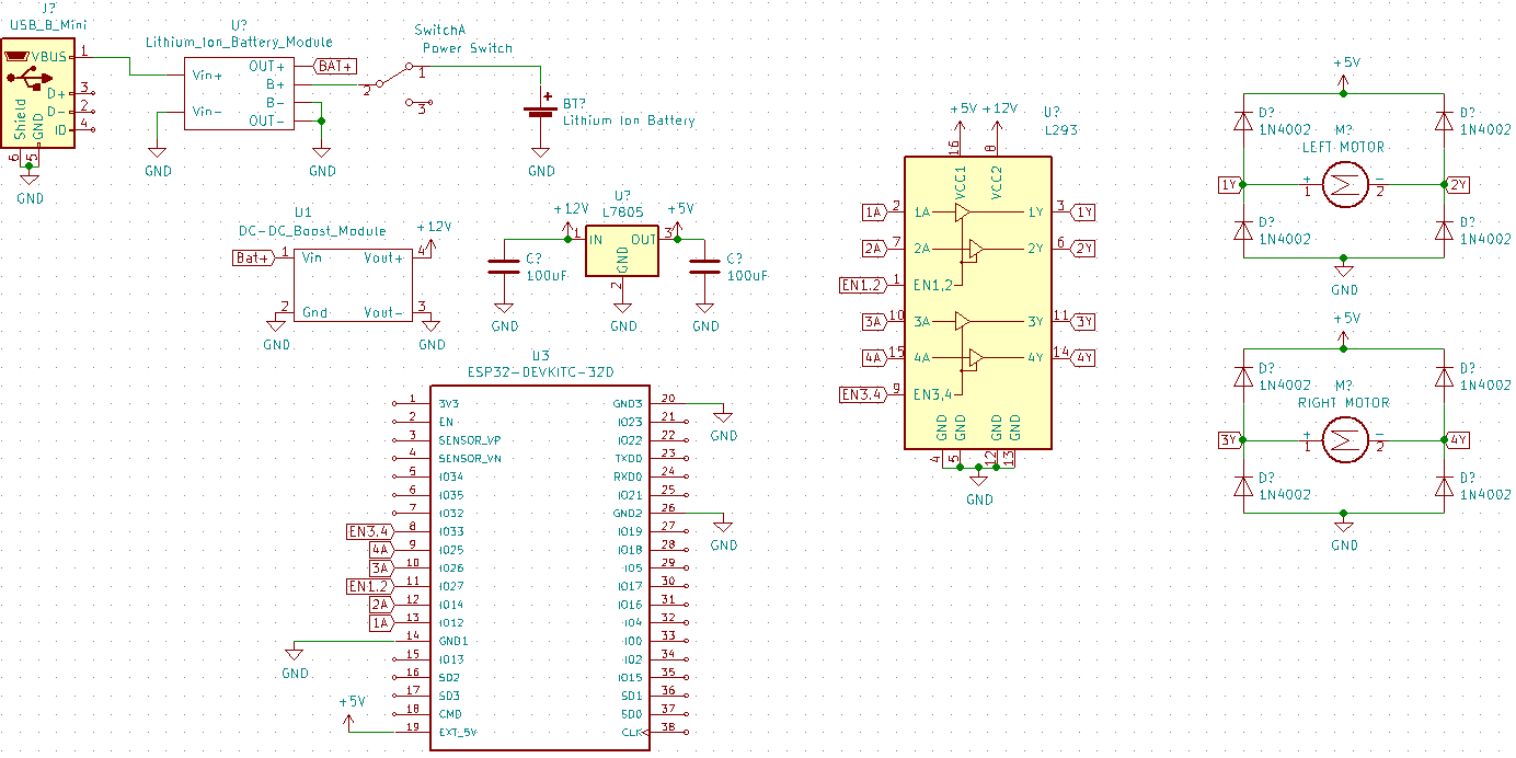
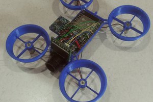
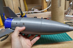
A simple WiFi controlled robot prototype for a club at my university. Uses the ESP32 dev board, a L293 dual H-Bridge, and is mostly 3D printed.
0%
0%
ESP32 Mini-Bot
A small proof-of-concept ESP32 Bot
Become a Hackaday.io member
Already have an account? Log in.
Just one more thing
To make the experience fit your profile, pick a username and tell us what interests you.
Pick an awesome username
hackaday.io/
Your profile's URL: hackaday.io/username. Max 25 alphanumeric characters.
Pick a few interests
Projects that share your interests
People that share your interests
 Jon VB
 ArsenioDev
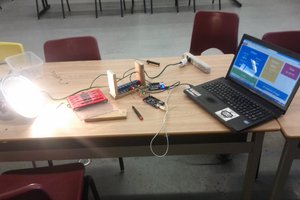
 Ansaf Ahmad