0%
0%
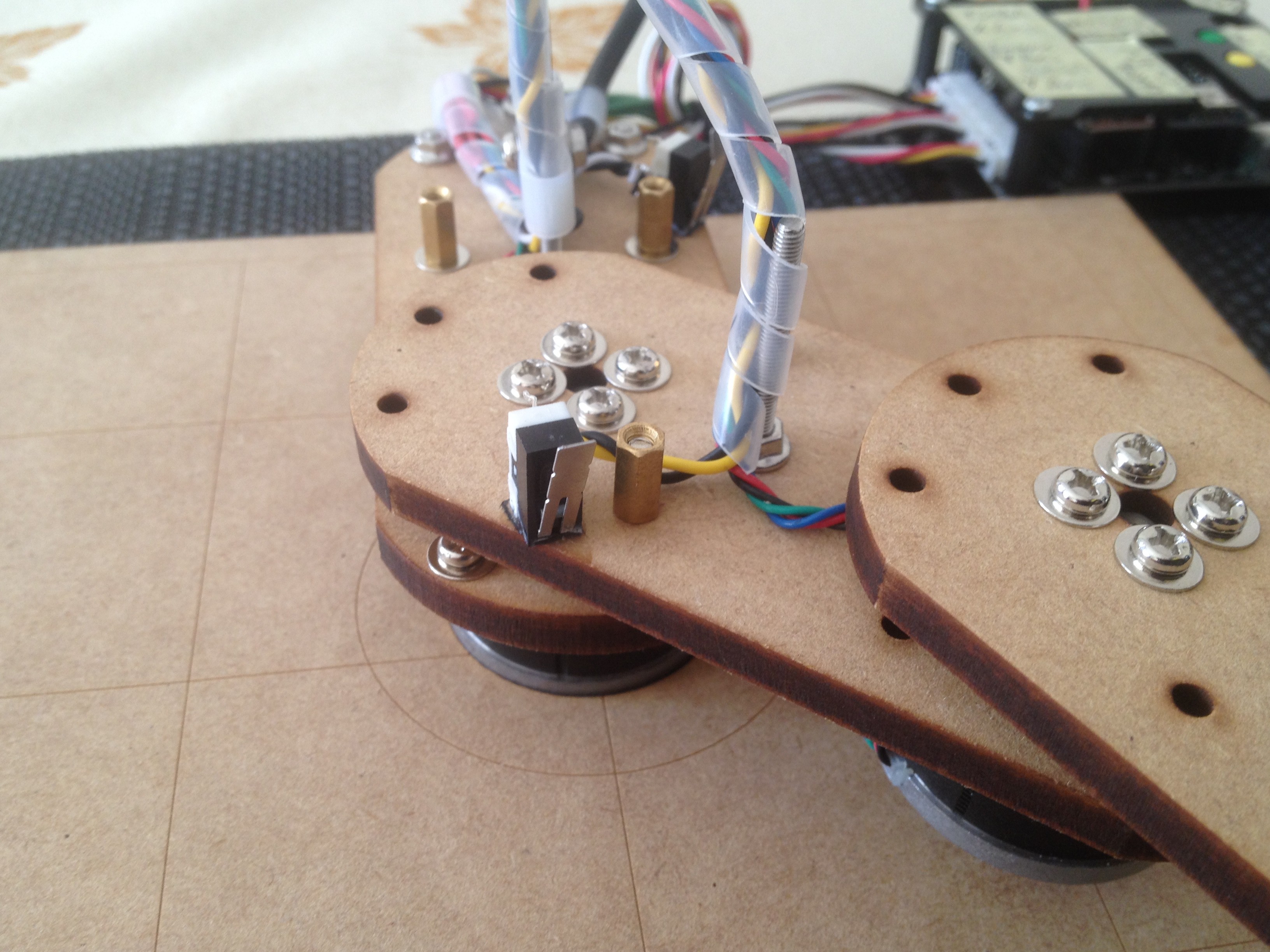
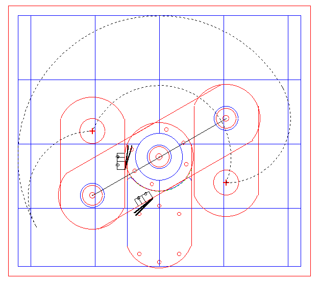
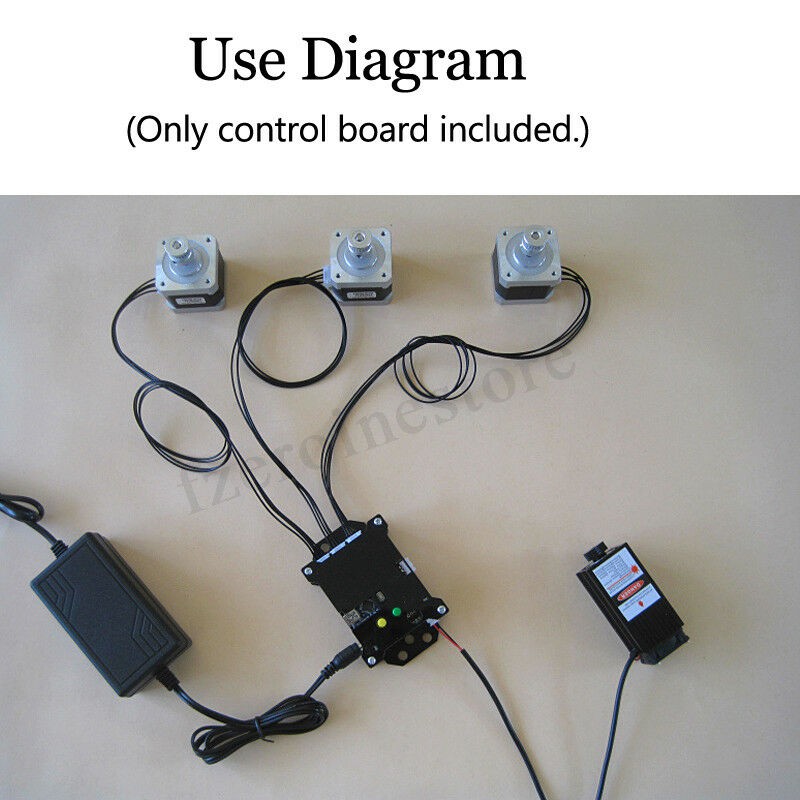
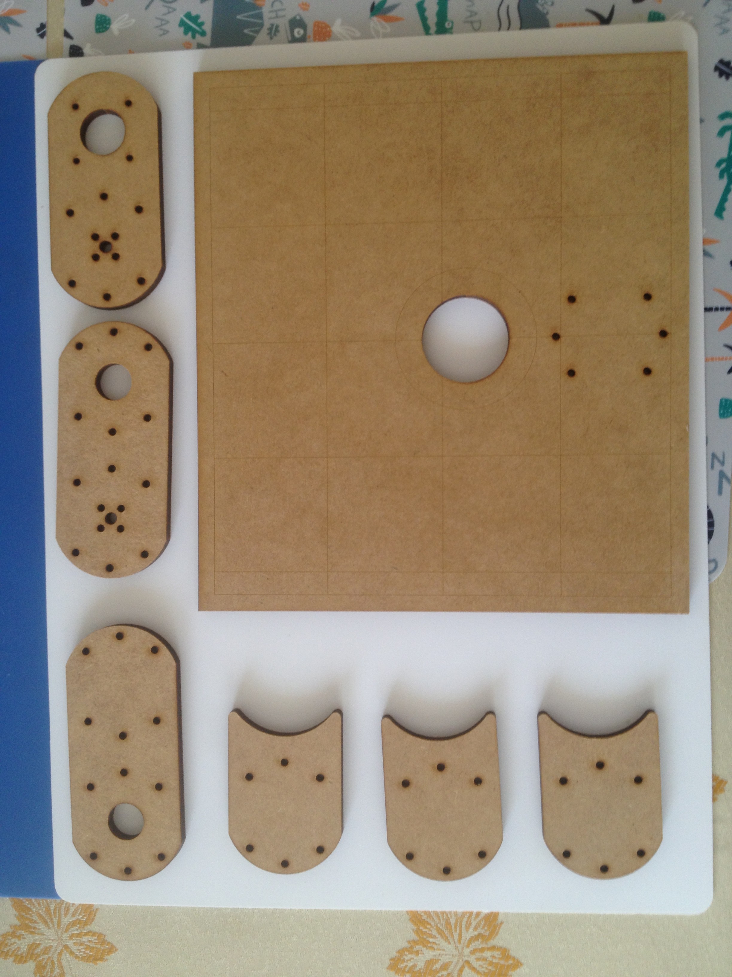
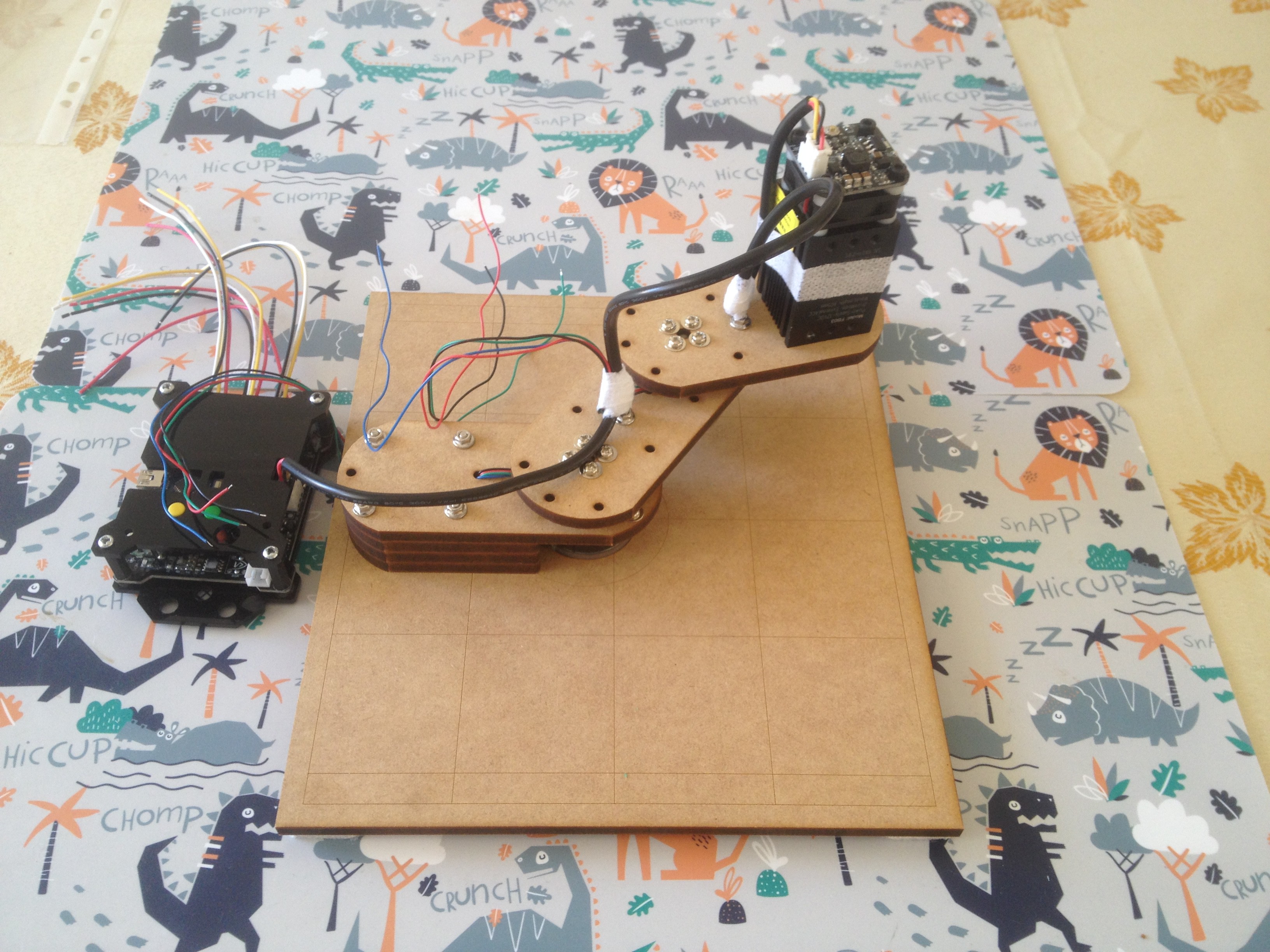
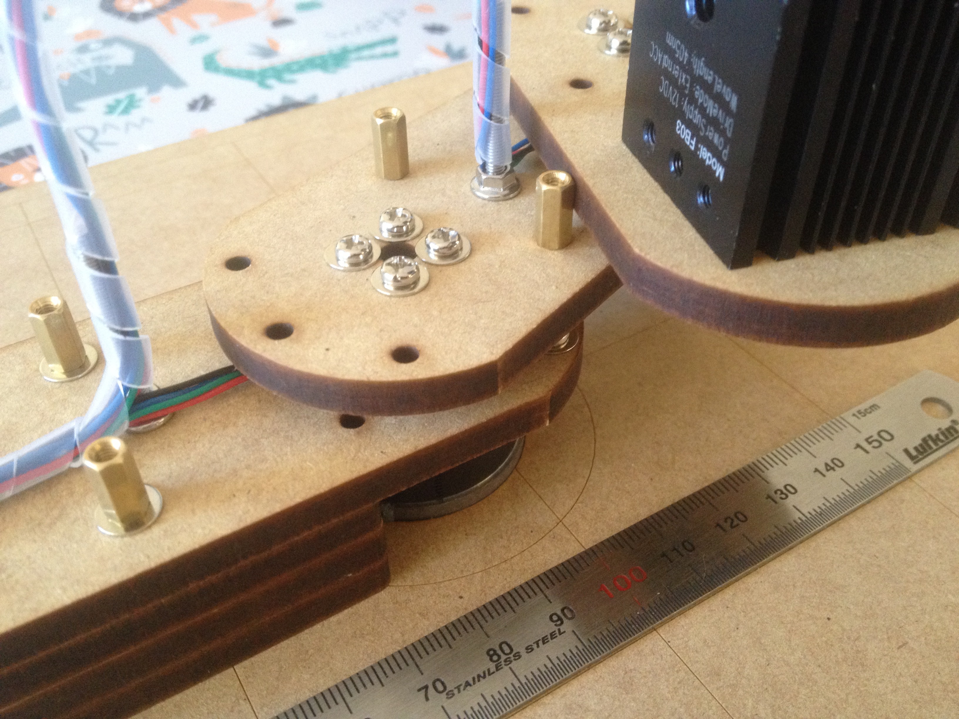
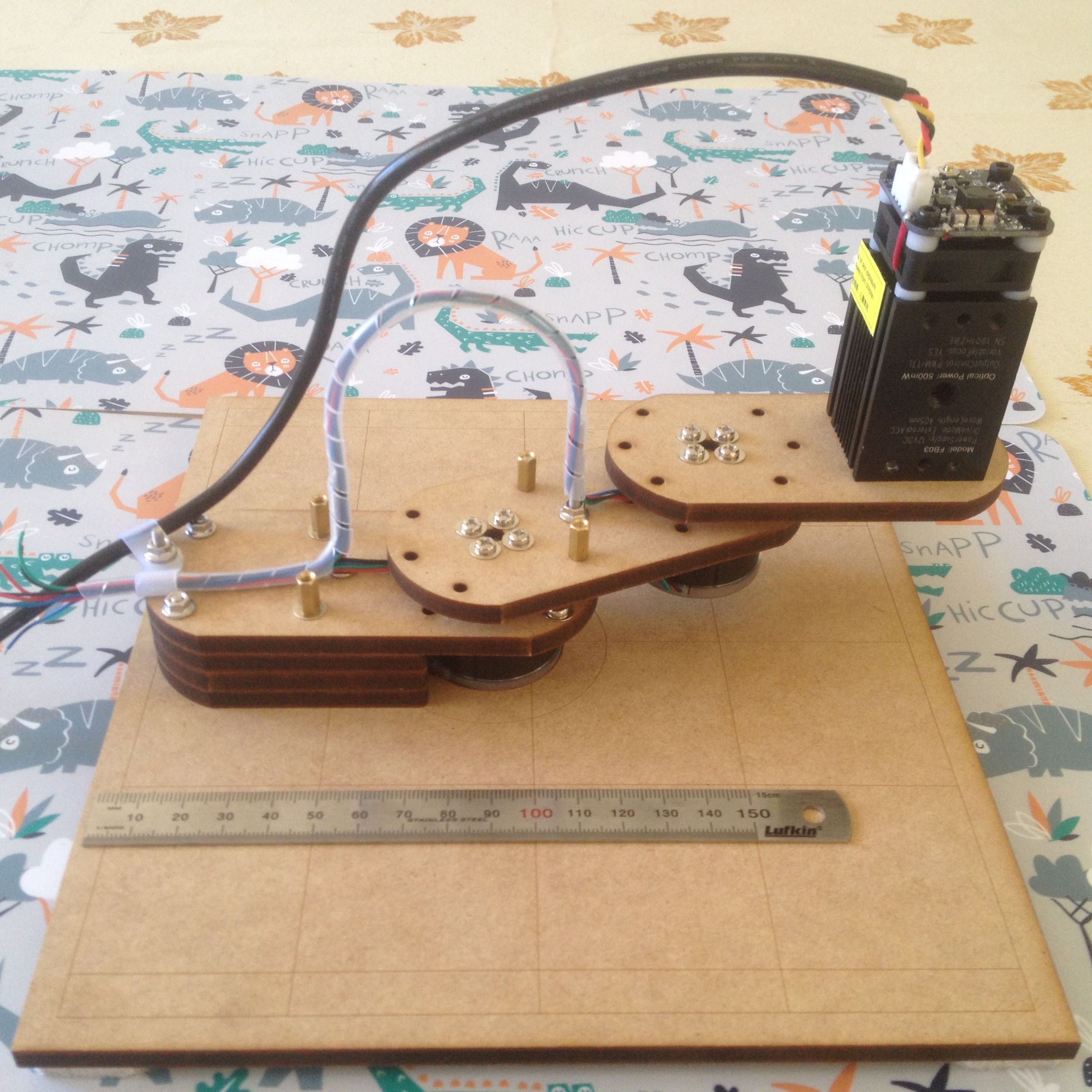
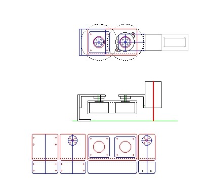
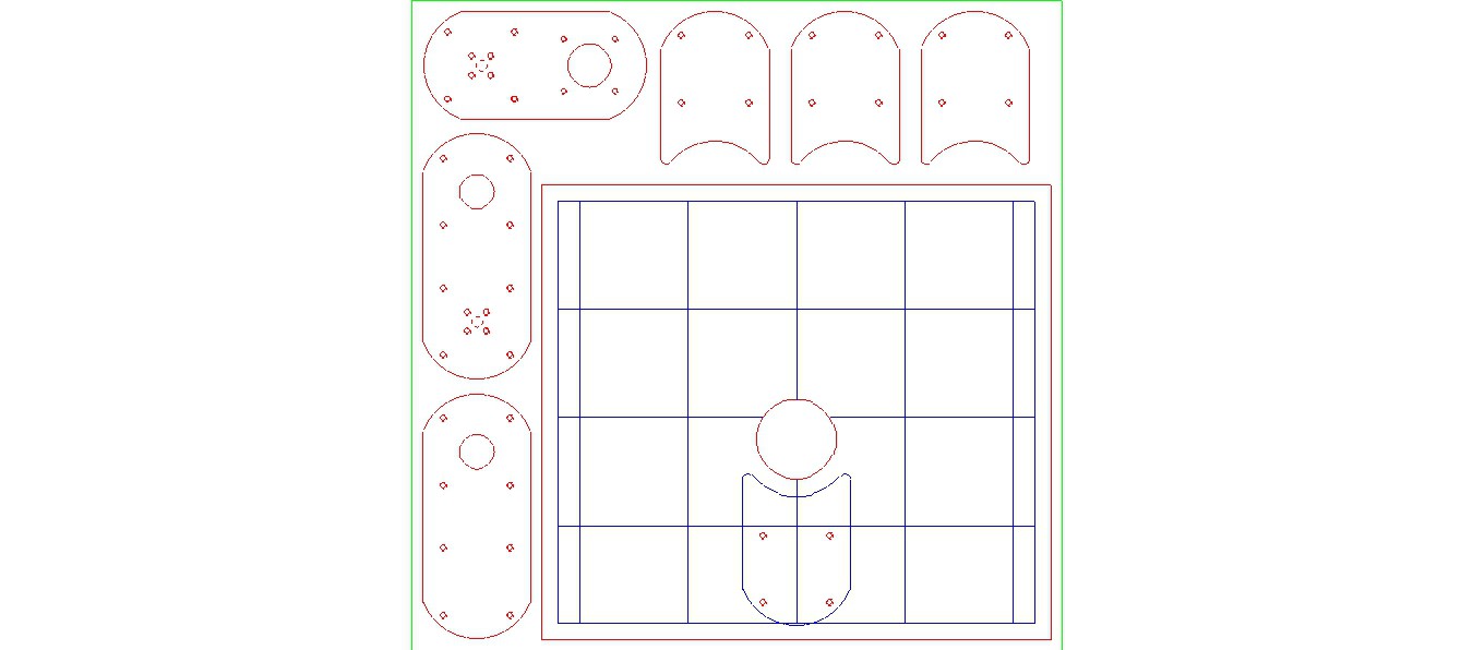
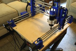
Prototype SCARA
A "demo" direct drive SCARA made out of MDF.
The idea is to test my SCARA Controller.
 agp.cooper
Become a Hackaday.io member
Already have an account? Log in.
Just one more thing
To make the experience fit your profile, pick a username and tell us what interests you.
Pick an awesome username
hackaday.io/
Your profile's URL: hackaday.io/username. Max 25 alphanumeric characters.
Pick a few interests
Projects that share your interests
People that share your interests
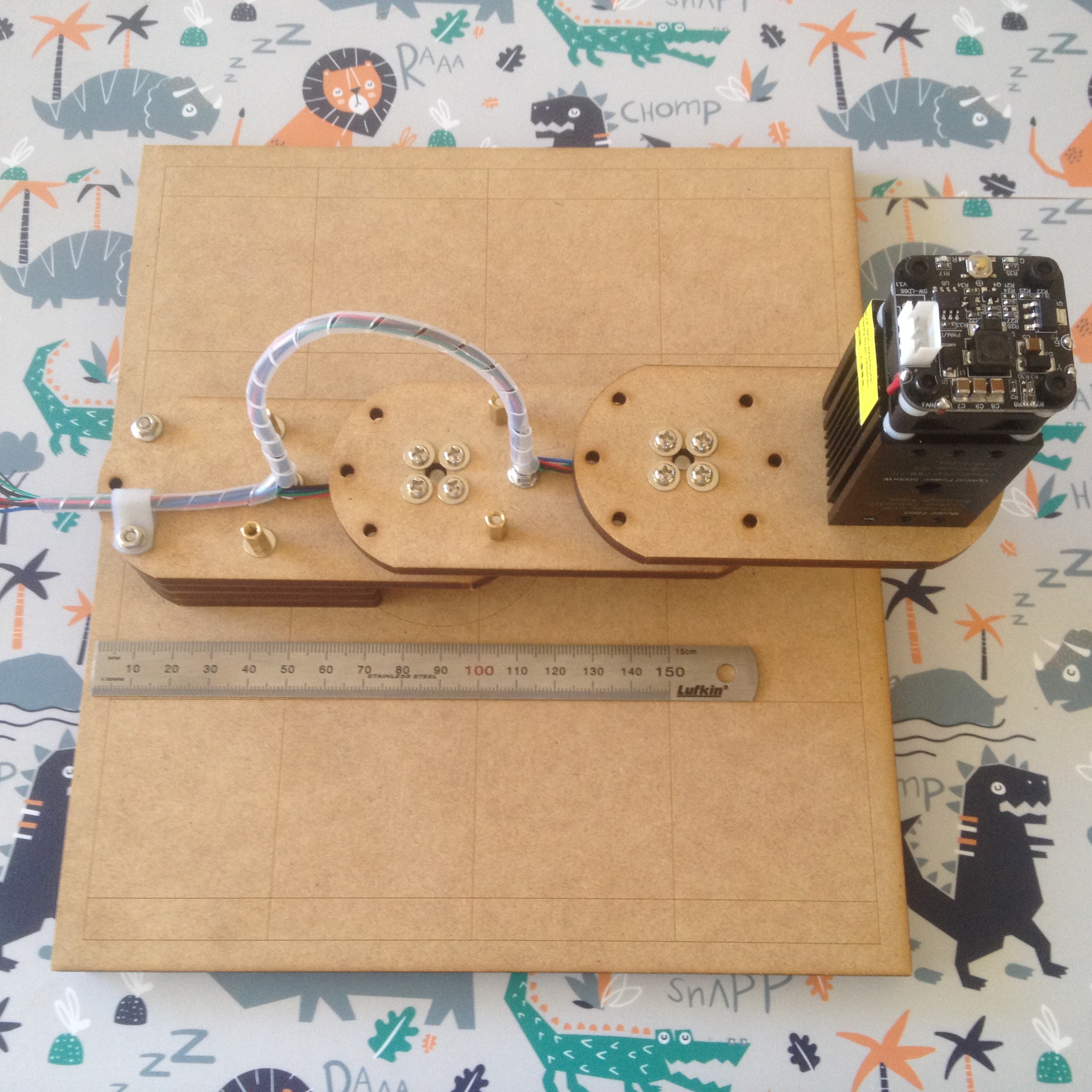
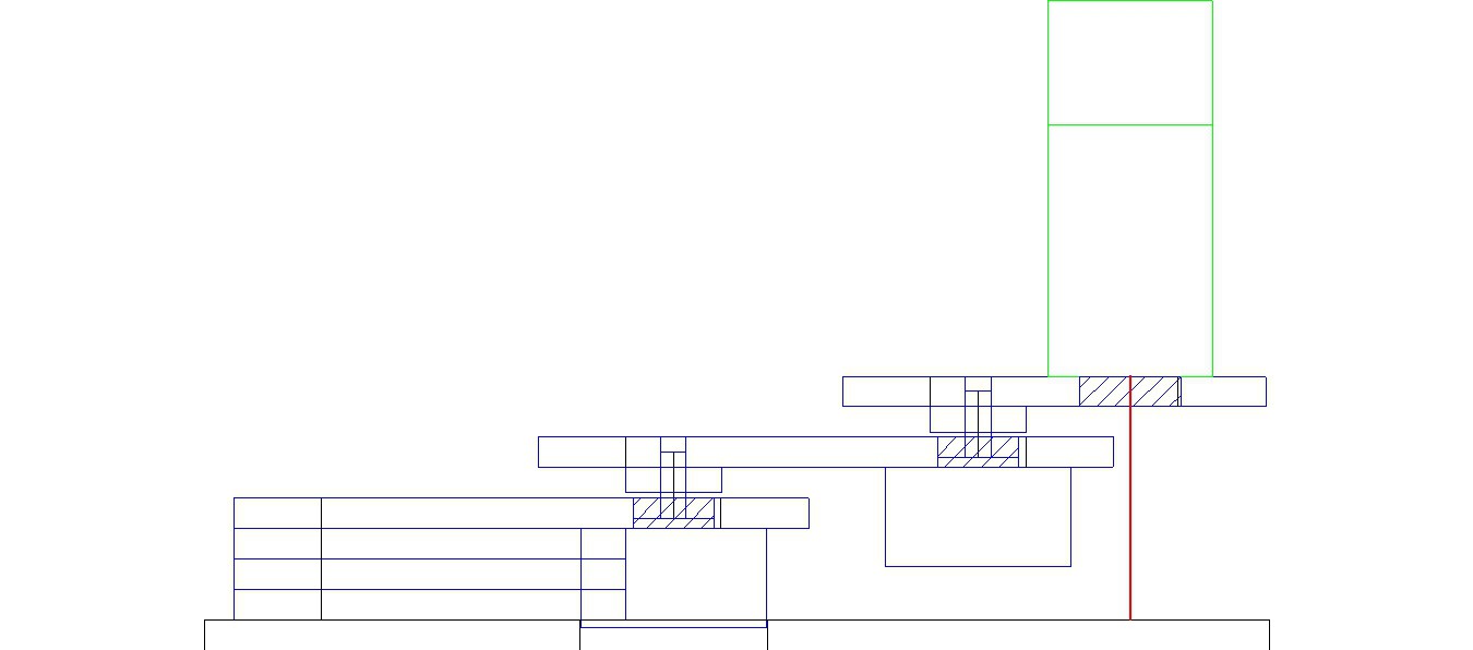
 The bending moment calculations suggest less than 0.5mm deflection (assumes 2.5N end load). Maximum end load is 30N (~5mm deflection).

 David Tucker
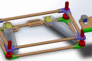
 Timo Birnschein
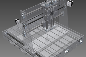
 Kert
Kert
Sorry for the late reply, Sandwiched Al or FRG would increase the stiffness significantly as would increasing the thickness of MDF.
Consider MDF with a Young's modulus of 3.5 GPa versus 70 MPa for Al. We get the same stiffness if the MDF is 2.7 times thicker (i.e. 2.71 = (70/2.5)^0.3333).
FRG has a Young's modulus around 8 to 12 GPa depending on the layup. So ball park 2 to 3 times stiffer.
So the best solution is a thick MDF - fiber-glass sandwich.
My biggest problem here is damping of resonance of the arms.
AlanX