I did originally plan on using stripboard for the final wiring of the sensors, however I think my electrics knowledge just isn't good enough... I designed the layout and attempted several times at the soldering of it - but no luck:
Have I messed up with this design???
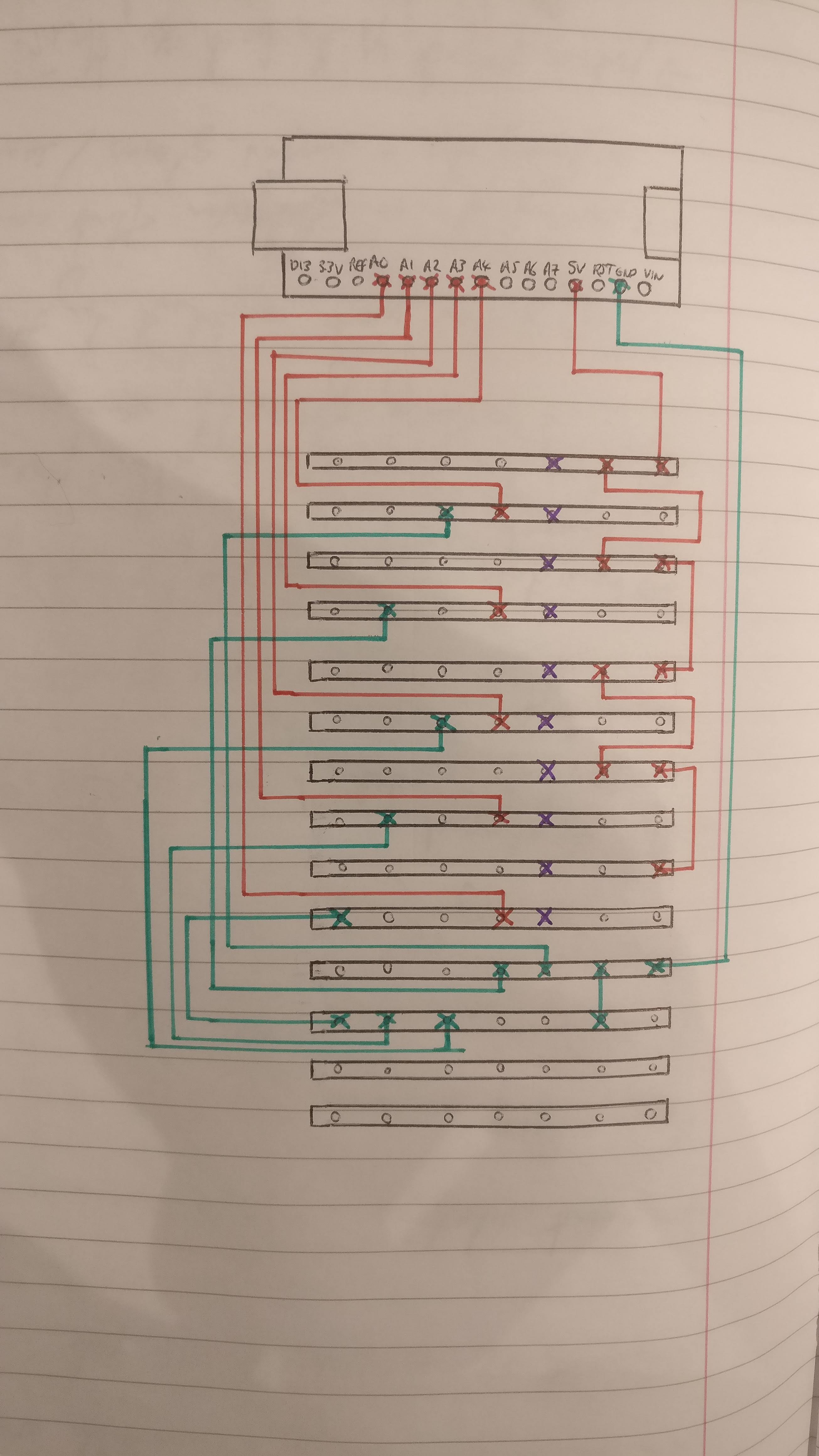
Where the purple represents the sensor connection points. The green represents the resistors going to ground. And the red represents the power pathway and the wire connections back to analog.
Discussions
Become a Hackaday.io Member
Create an account to leave a comment. Already have an account? Log In.