-
Project Update
03/14/2019 at 22:46 • 0 commentsHere's a video of the device 'smartwatch' in action:
Few things left to do still, want to finish off the GUI aesthetics, complete the Raspberry Pi House, attach the senors and Arduino house to glove, attached the strap to the Raspberry Pi House. Then if time permits in this project, to move the sensors to the wrist strap and code the gestures to be recognised from those contact points.
-
Raspberry Pi House #1
03/14/2019 at 21:39 • 0 commentsThe Raspberry Pi House is coming together now. However I made a big error when it came to the charging access point, which has resulted in me having to cut out a hole. So the one side now is a bit ruined. If i have time towards the end of the project, I will reprint the case to improve its aesthetics.
![]()
Here's the side which a hole was required to be post assembled cut:
![]()
Not terrible... right...? Haha
Having the backing board for the speaker has increased its power tremendously. Now functions as a pretty good speaker for this size device.
![]()
I will measure up and print out the remaining sides to fill it in another time. To have this now though is another great step in the right direction.
I will post a video in my next log of it in working order to show where the projects at currently.
-
Raspberry Pi house
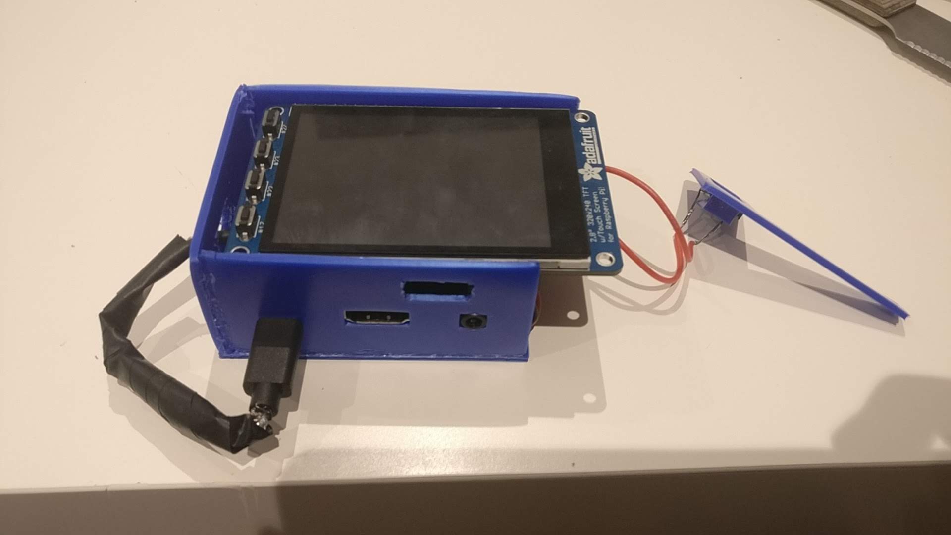
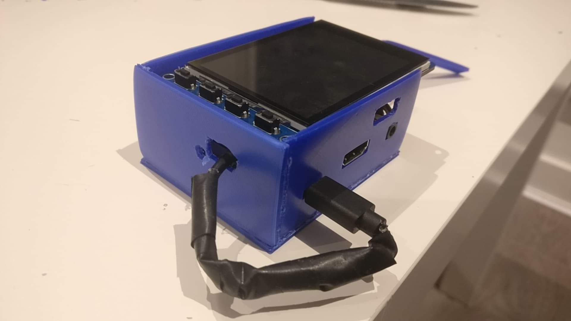
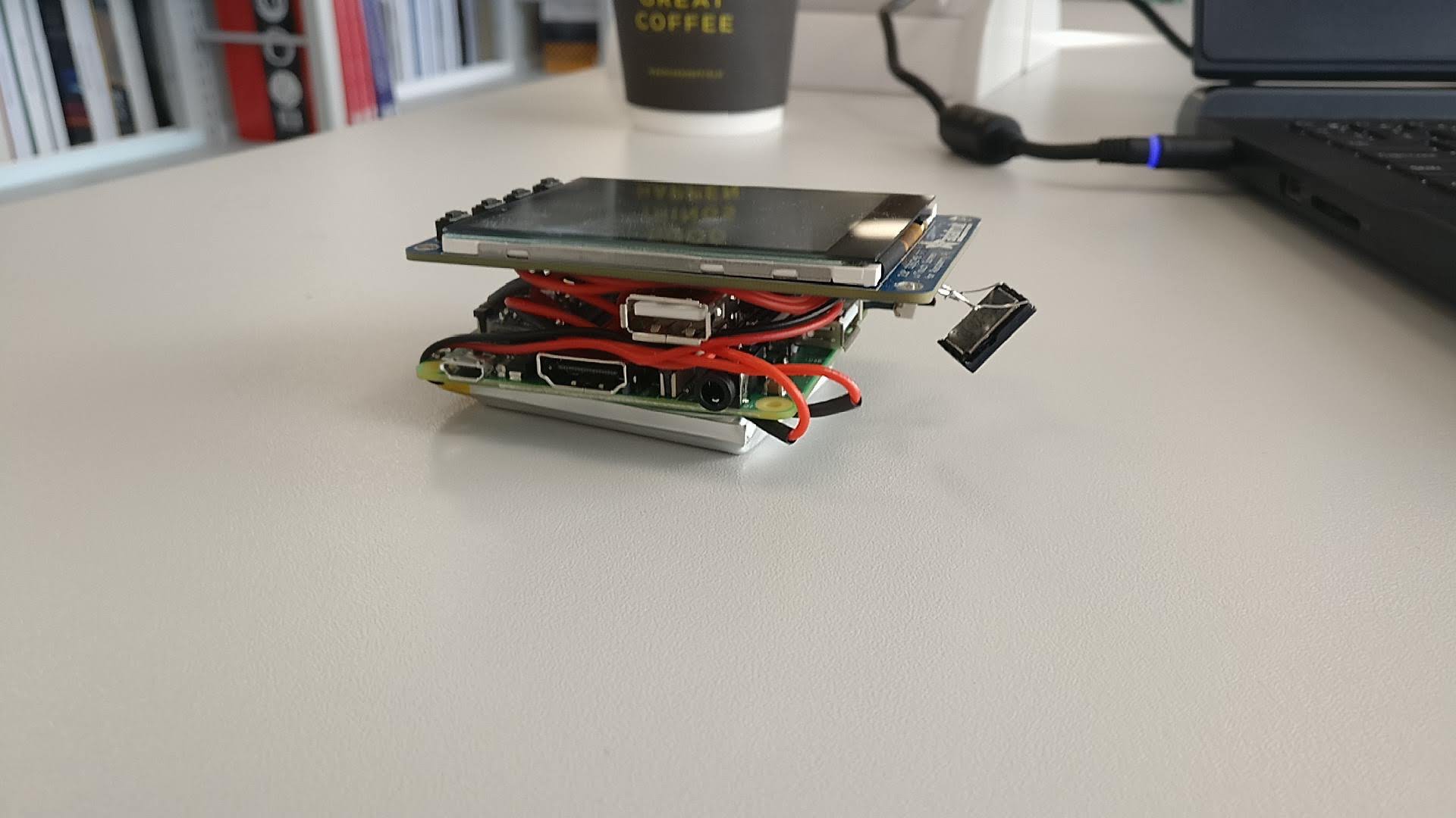
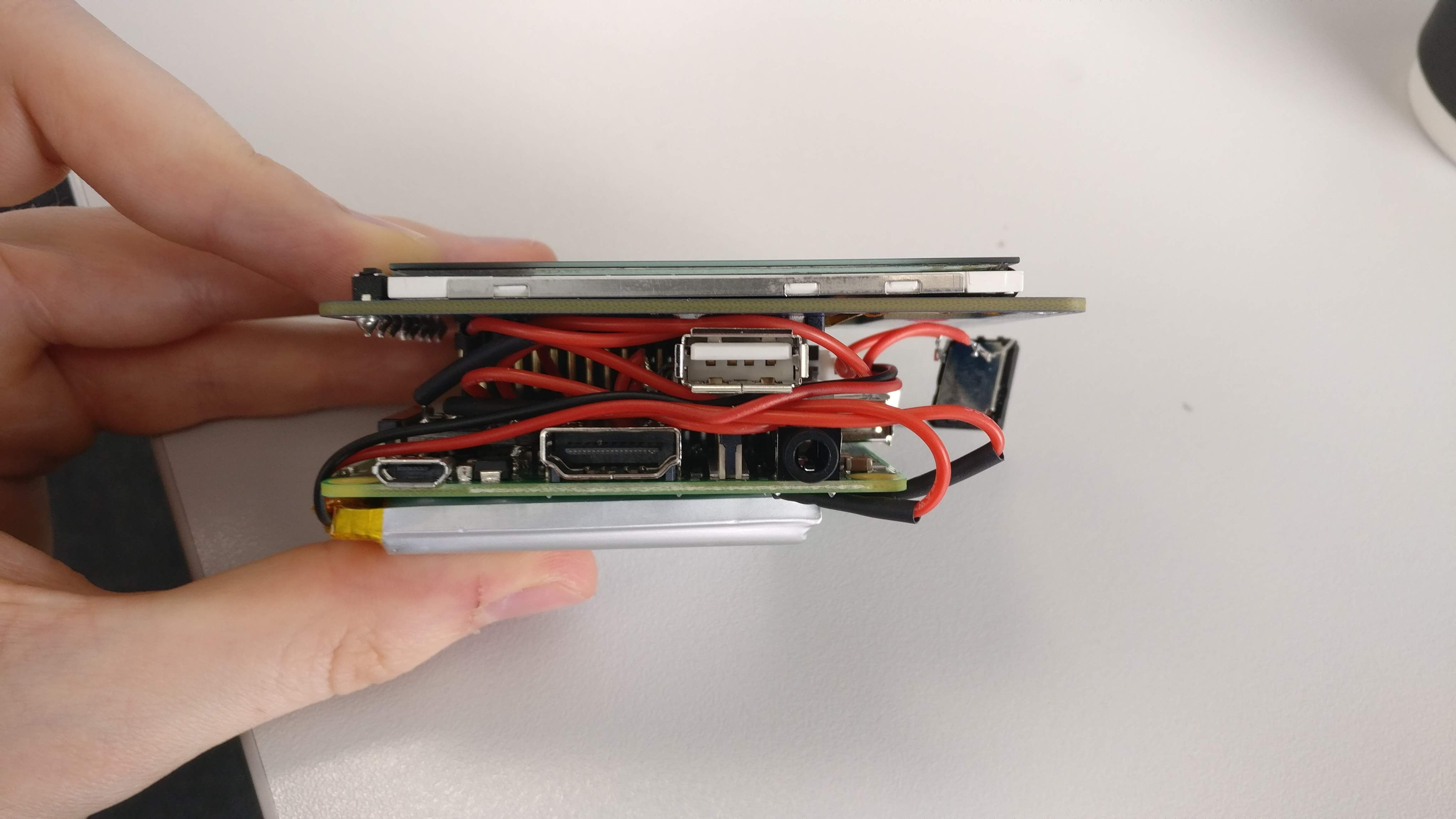
03/14/2019 at 21:21 • 0 commentsNow its time to design a housing/case for the Raspberry Pi. The main 'watch' aspect of the project. There are a lot of ports to take into account and I want to keep access to them all. I've compacted all the wiring and board into the final 'shape' so I know what kind of size i'm working with.
![]()
For the first time delving into electronics and taking on this kind of project, I'm pretty happy with the final thickness I've achieved here.
![]()
-
Arduino House #2
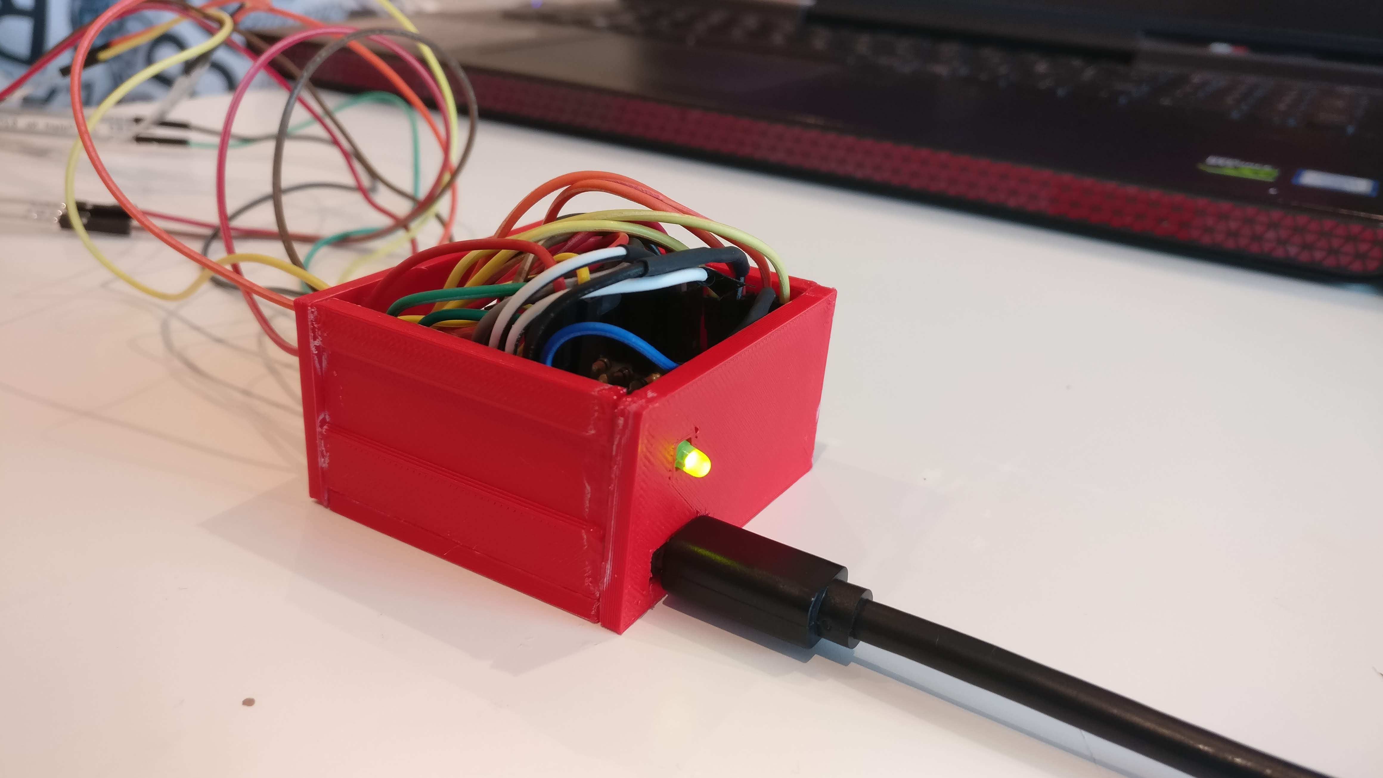
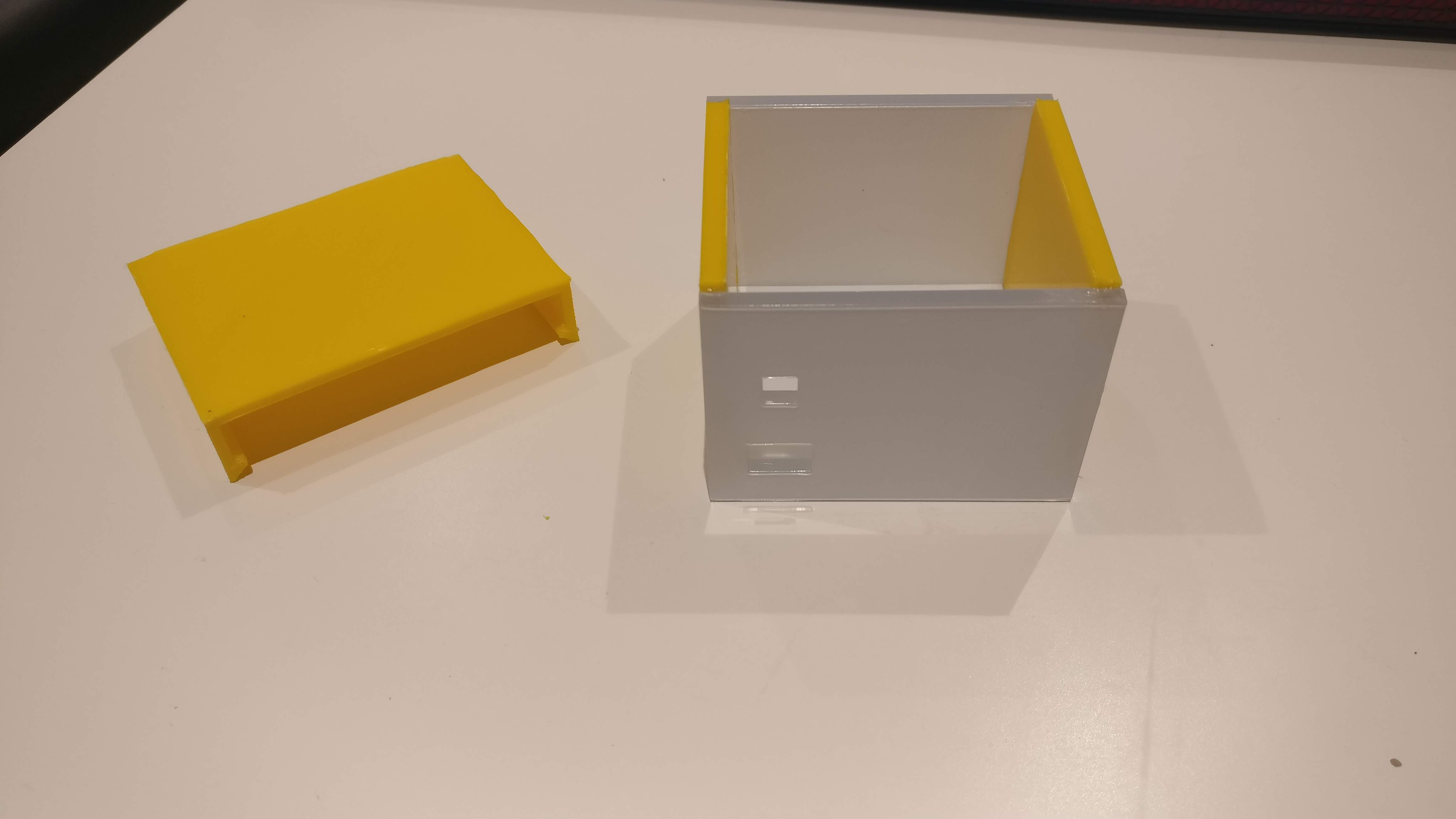
03/14/2019 at 21:18 • 0 commentsSo after tinkering with the dimensions, I have reprinted the Arduino Case, its lost a lot of size and is a perfect fit for the components it has to house, with the power connection point and Power LED held in position stably.
![]()
![]()
-
Arduino House #1 - Too Big!
03/14/2019 at 21:15 • 0 commentsIt seems I was a bit too generous with the dimensions of this first attempt.
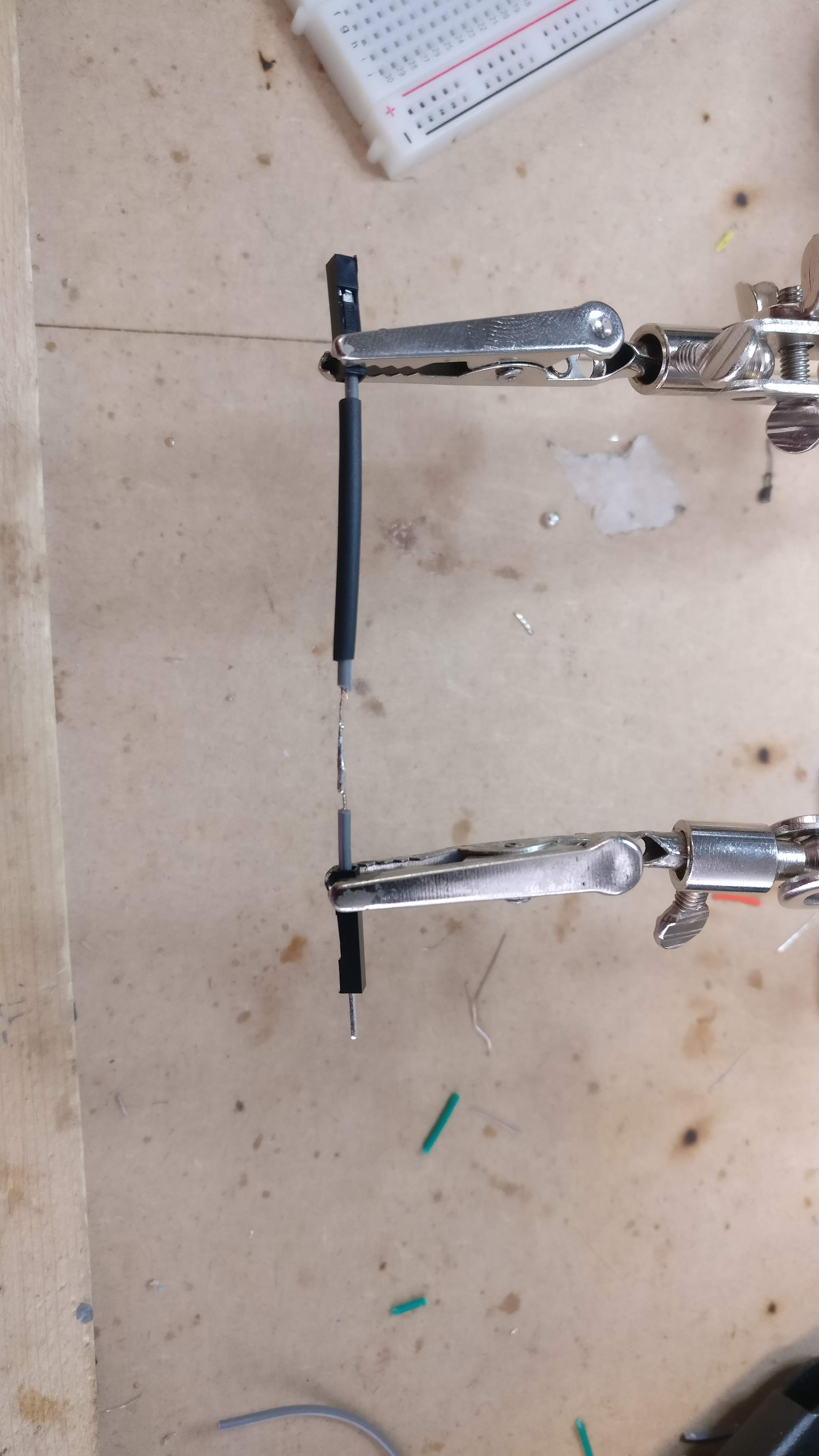
After splicing and soldering all the wires down shorter, like so:
![]()
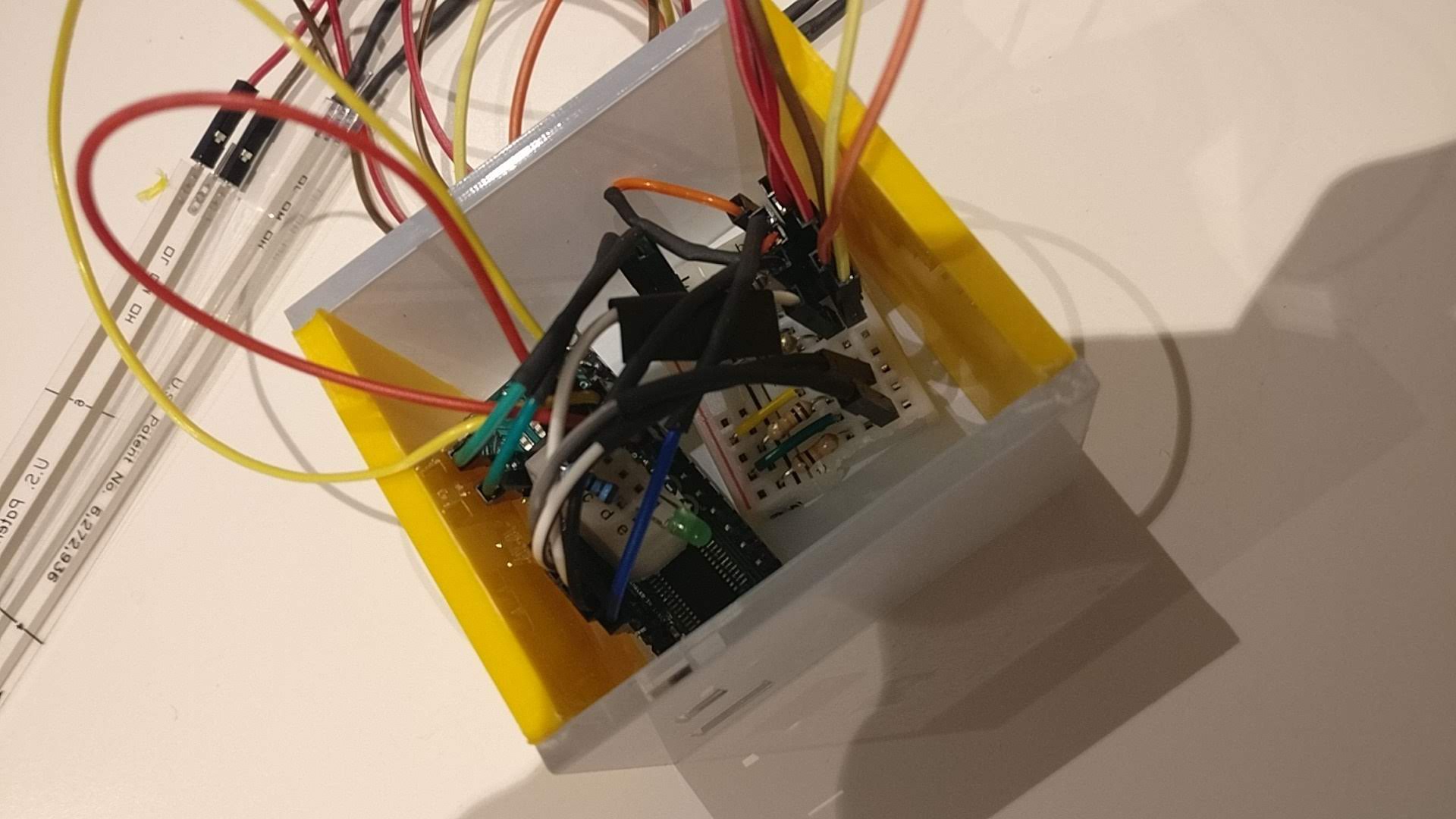
And then after placing the sensor wiring/breadboard/arduino into the housing, it was apparent how much unused volume of space there was.
![]()
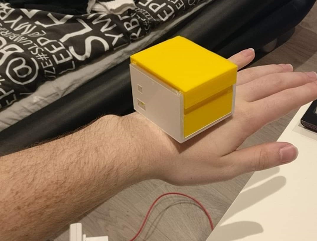
Also, placing it on the back of my hand, where this house will sit, shows just how large and cumbersome this house would be.
![]()
Back to the drawing board to make a smaller version...
-
Arduino House #1
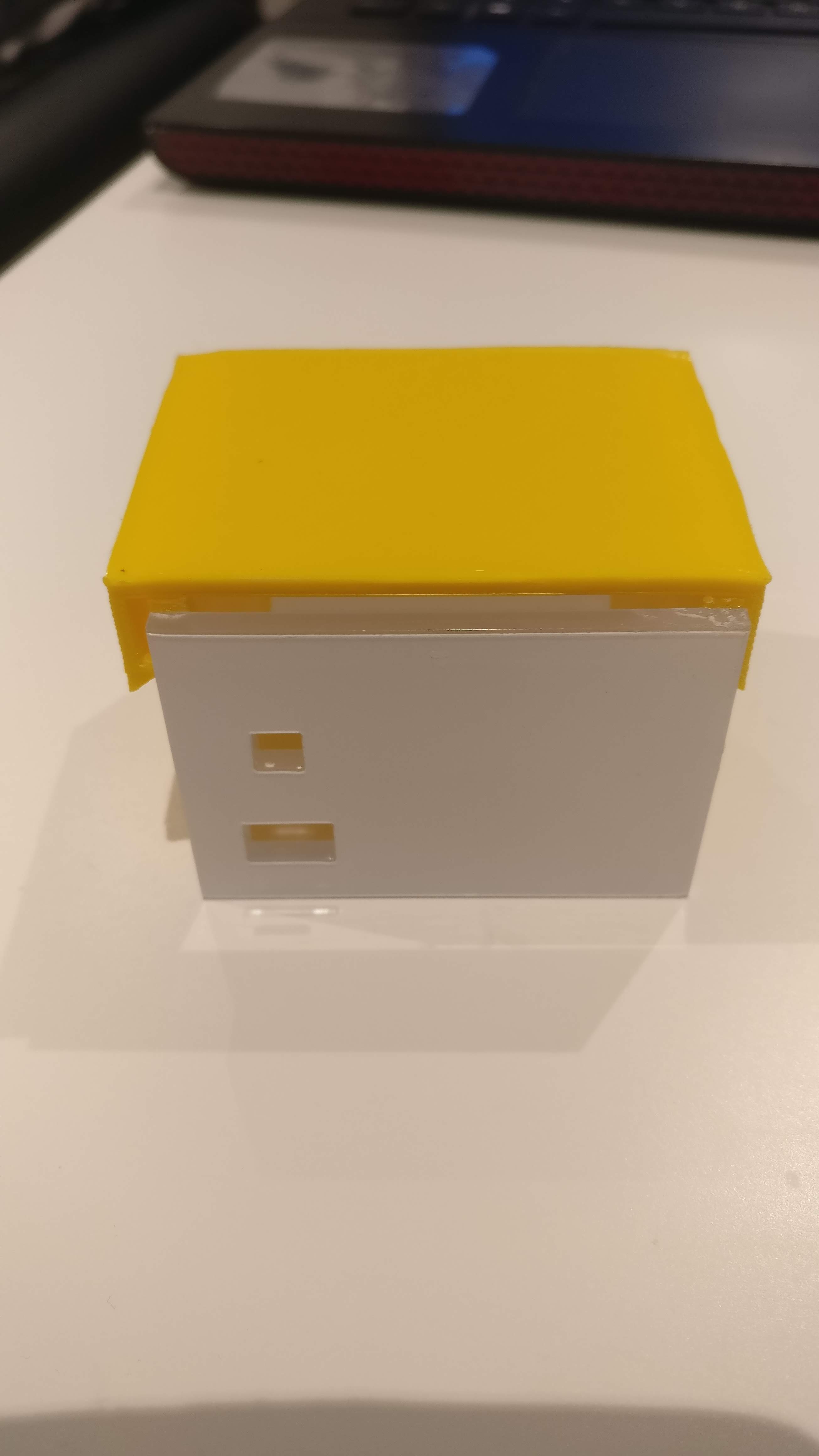
03/14/2019 at 21:09 • 0 commentsSo using a mixture of 3D printing and Laser cutting and a quick mock up on CAD, I've made a first attempt for the Arduino House:
![]()
![]()
Two holes on the front, one for the power/data transfer cable, the other for the green power indicator LED. One the back, a large hole for the sensors to pour out from.
-
Power Light for Arduino House
03/14/2019 at 21:04 • 0 commentsI then realised that it would be very handy to know if the Arduino was getting power when it is inside this box., as the pre-manufactured light on the arduino board itself would not be visible anymore.
So using another little section of breadboard and a connection to one of the arduino's digital pins, a couple of lines of code later and it was sorted.
![]()
![]()
-
Shrinking down the Sensory Wiring on the Breadboard
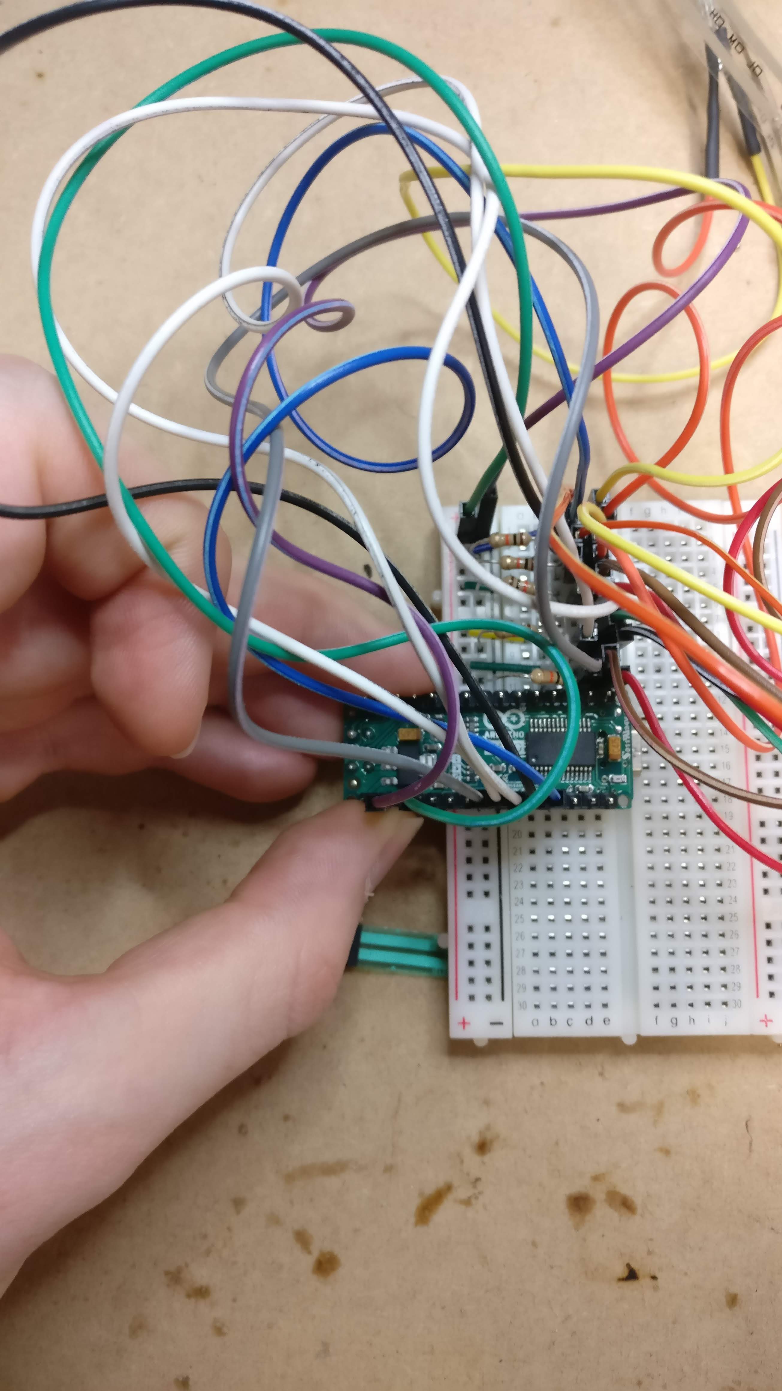
03/14/2019 at 21:04 • 0 commentsTo keep moving forward with the project I going to continue using the breadboard for the sensor wiring into the final concept device.
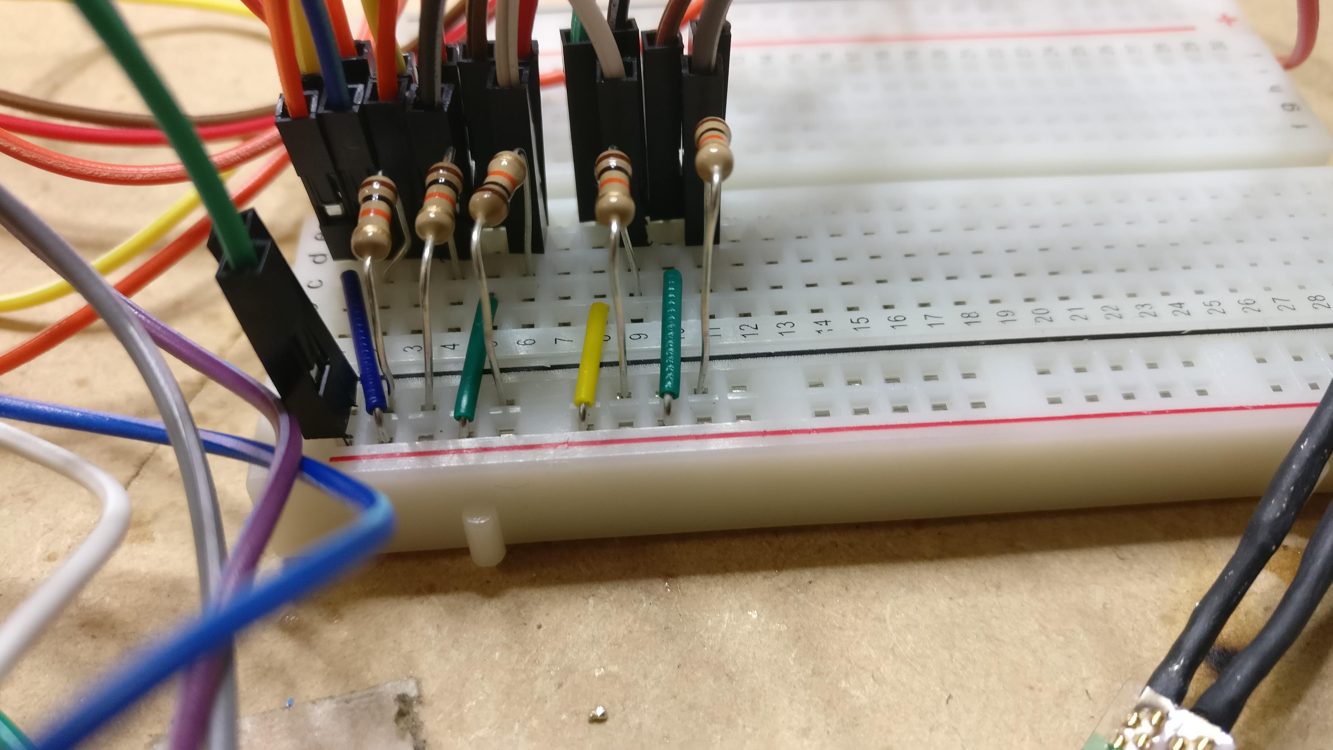
So after rewiring everything to be as small as possible:
![]()
The idea is then this small section of breadboard and the arduino will sit in the 'Arduino House' case on the back of the hand, like so:
![]()
-
Separate Housing/Cases
03/14/2019 at 21:04 • 0 commentsI've decided to separate the Arduino and Raspberry Pi into different cases - as a space saving measure. I don't want this device to become too large for the wrist, to the point where it would become uncomfortable.
So I will have one case which will be the 'watch' which will house the Raspberry Pi, battery, speaker etc. And another case which will house the Arduino and sensors circuitry. This case will sit on the back of the hand.
-
Sensor Circuitry - Making it smaller
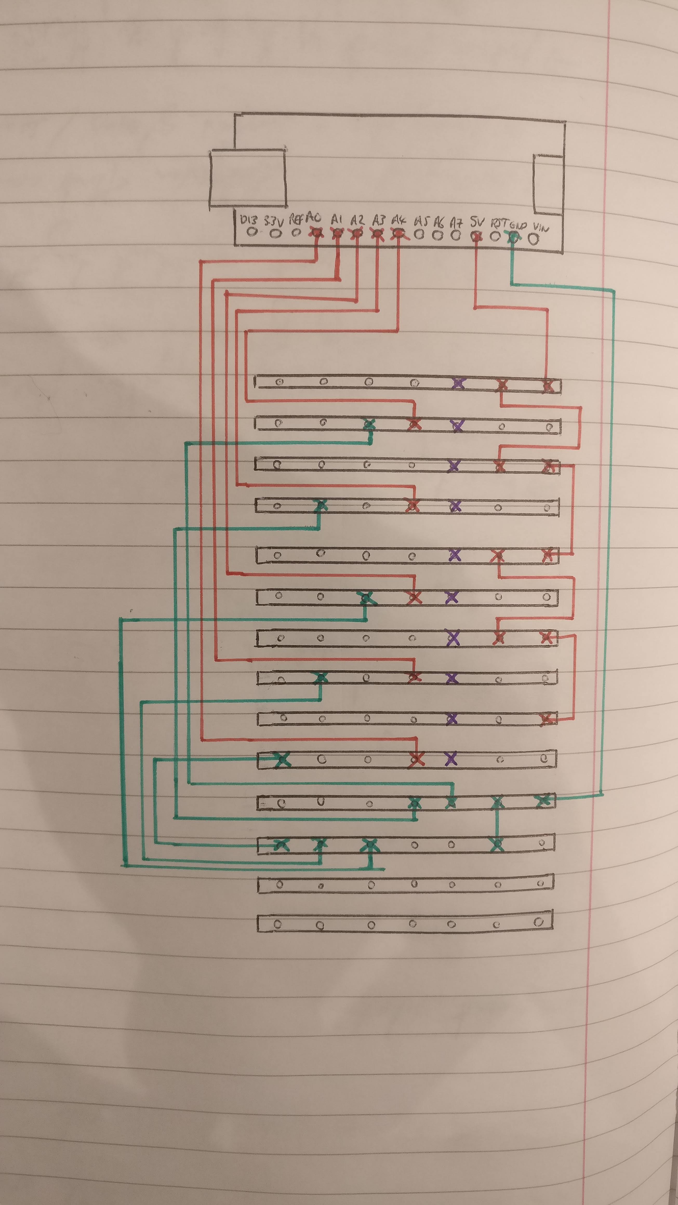
03/14/2019 at 20:54 • 0 commentsI did originally plan on using stripboard for the final wiring of the sensors, however I think my electrics knowledge just isn't good enough... I designed the layout and attempted several times at the soldering of it - but no luck:
Have I messed up with this design???
![]()
Where the purple represents the sensor connection points. The green represents the resistors going to ground. And the red represents the power pathway and the wire connections back to analog.
Gesture Controlled Smartwatch
A larger, more functional smartwatch with gesture controllability