-
Solving the x00 Serial Arduino Problem
03/04/2019 at 18:16 • 0 commentsWell I have found a solution to this Serial Connection x00 problem:
By including an if statement which looks at the serial port incoming data, and if it doesn't match a certain format of 5 numbers, like the expected, correct incoming data from the FSR Sensors:
0, 0, 0, 0, 0
then it will dump the reading, and replace it with a reading of zeros, like above. Now only the correct formatted readings are delivered to the List in the Kivy GUI app code, and no longer any issues with the numeric property that defines said list.
This solution, I think, will actually help against all kinds of potential future bugs from the sensor data incoming along the serial connection.
This is the code in the arduinothread.py file I have included:
def read_serial(self):
"""Returns a list of from serial monitor."""
reading = self.serial.readline().decode('utf-8')
reading = reading.strip('\r\n').split(',')
if len(reading) == 5:
return reading
else:
return [0, 0, 0, 0, 0] -
Serial output x00 problem - Arduino Nano
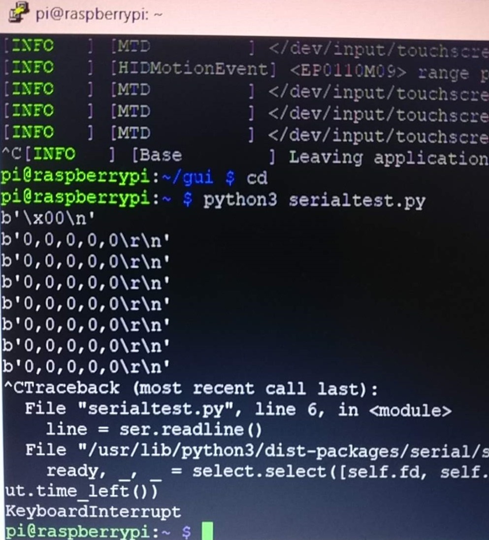
03/04/2019 at 18:16 • 0 commentsNow that I've moved from using the Arduino Uno to the Arduino Nano, i've come across a problem. The first line, everytime, that comes through to the Pi through the serial connection is this x00. Which is then having a domino effect, as the splicing and numeric property of the list that is generated for the sensor readings from this input cant function, and so the GUI fails. Below shows this output, using the simple serial test code:
![]()
I don't know why this is?? If anyone can shine any light on it??
Is it the move from the Uno to the Nano?
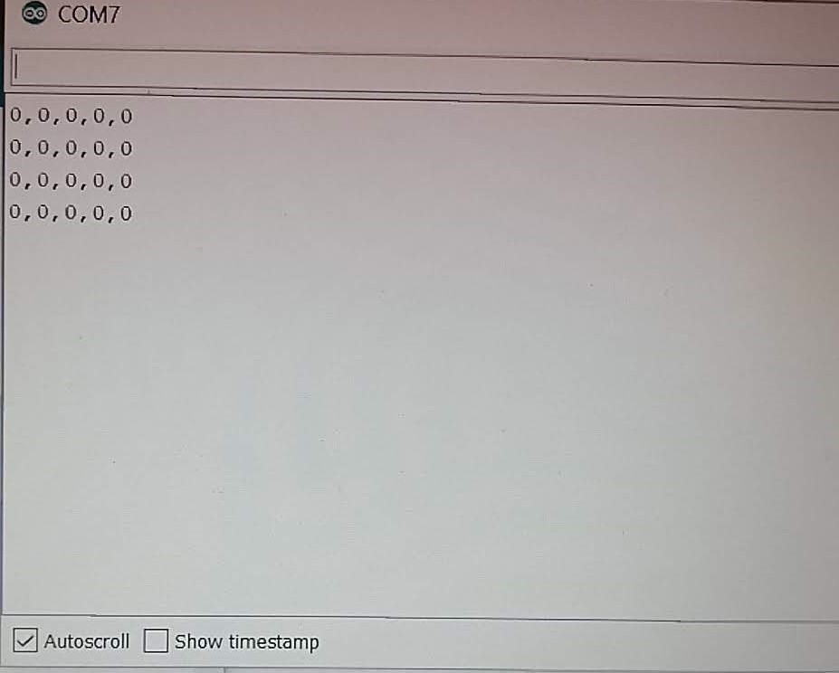
This seems to be a fault with the Raspberry Pi side of things, as when I connect the Arduino Nano and FSR Sensors into to the computer and run the serial monitor in the Arduino IDE, its transmitting just the numbers and comma's as instructed:
![]()
-
Arduino Nano, Breadboard & Floating Voltages
03/04/2019 at 18:16 • 0 commentsTo continue decreasing the size of this device, I'm changing out the Arduino Uno for the Arduino Nano. I've almost brought 2 more Flexiforce FSR Sensors that I have connected up, bringing the total up to 5 (one for each finger).
I had a big issue when I went about doing this, some sort of floating voltage came about - in both boards... giving me random readings from the sensors. Had to un-wire everything and wipe the boards clean, re-type out the code and re-upload, and what I think solved it was connecting the 5V with a jumper wire directly to the ground for a moment... maybe it drained this floating voltage out of the circuit??
No idea how this came about??...
I've also taken out of the breadboard and the Arduino code, the LED related software and hardware, as this will not be needed in the final product form and allows me to know the minimum size needed for my breadboard.
-
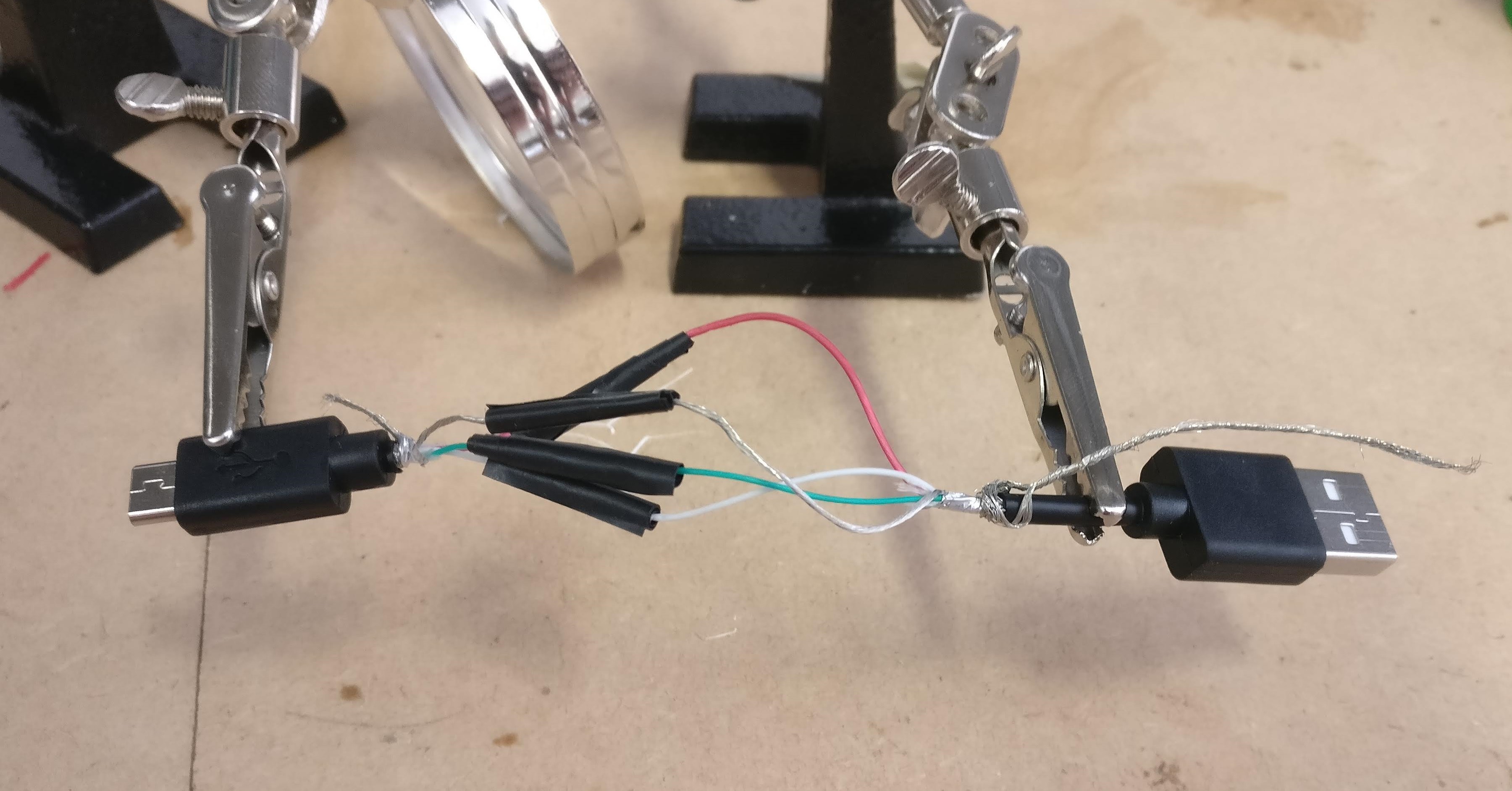
USB Splicing
03/04/2019 at 18:10 • 0 commentsAs you saw from the project schematic in the last entry, there is always a micro USB from the powerboost charging board to the pi itself. Which is constantly connected and will need to be inside the housing of the watch in the final product form.
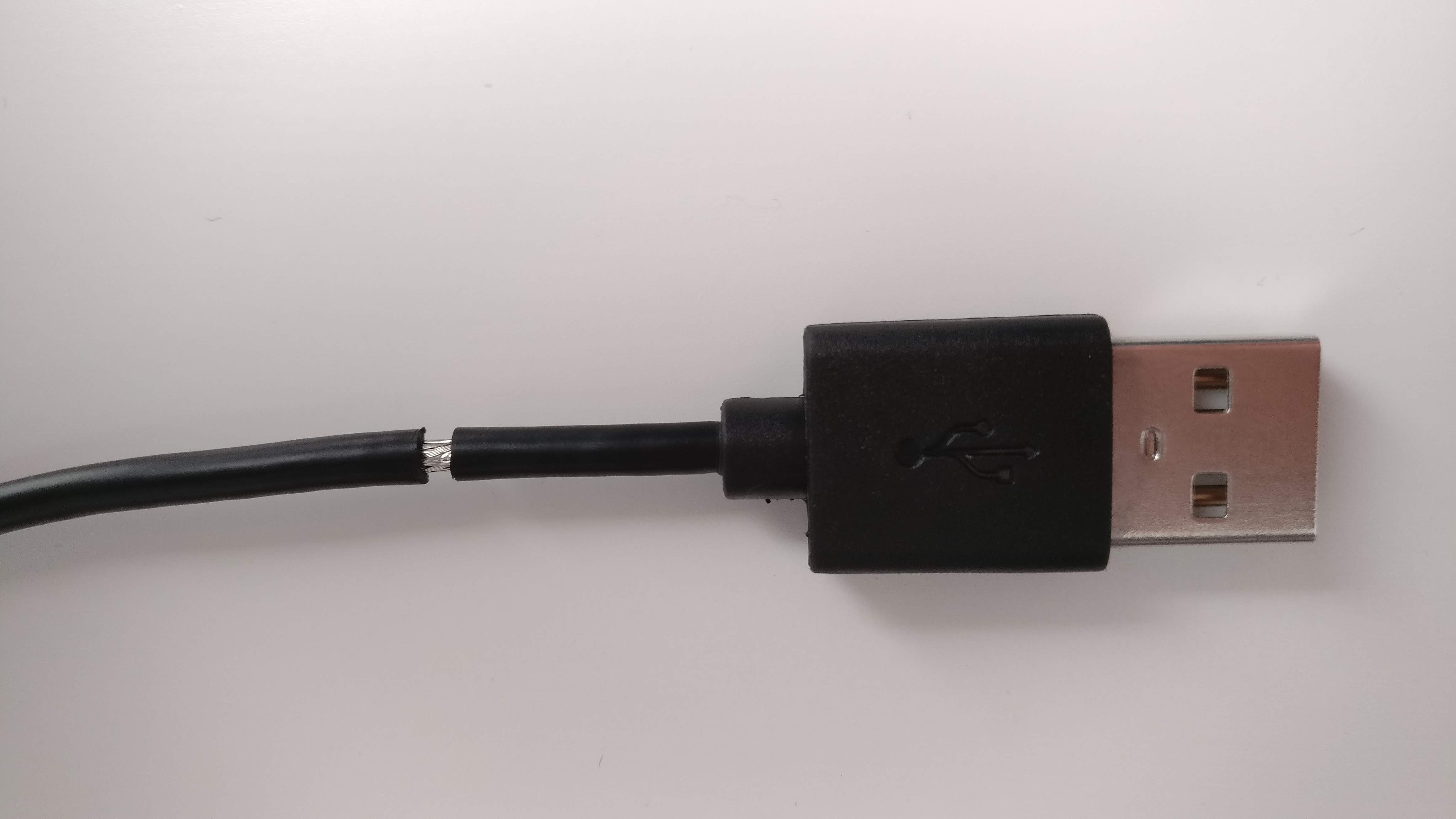
My micro USB cable is 1m in length, which will take up a lot of space/volume in the watch house, so in order to reduce the size needed to be the very smallest it requires, I have spliced this micro USB Cable to only a few inches long, i daren't go any shorted due to the intricacies of the wires and lengths when soldering involved.
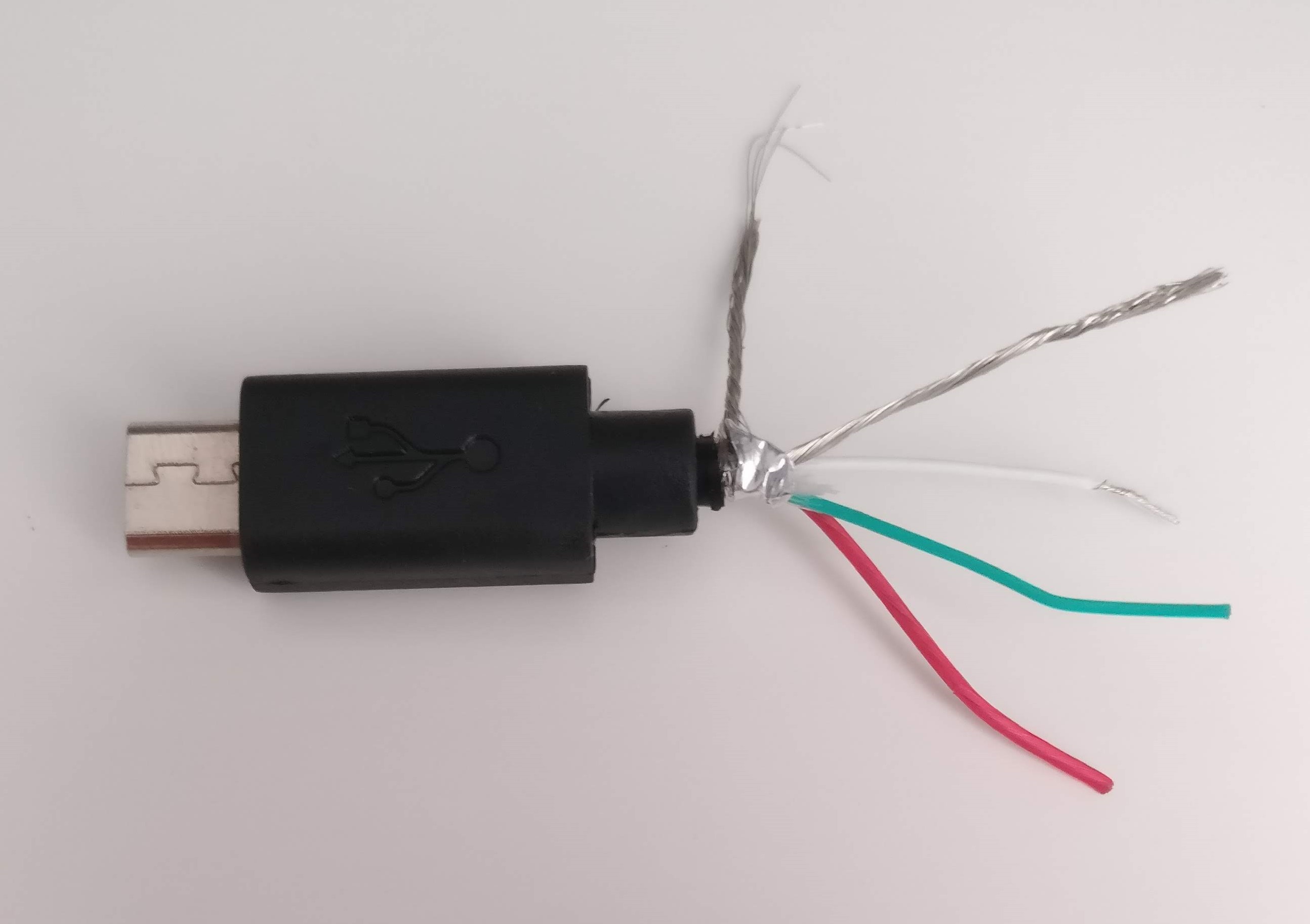
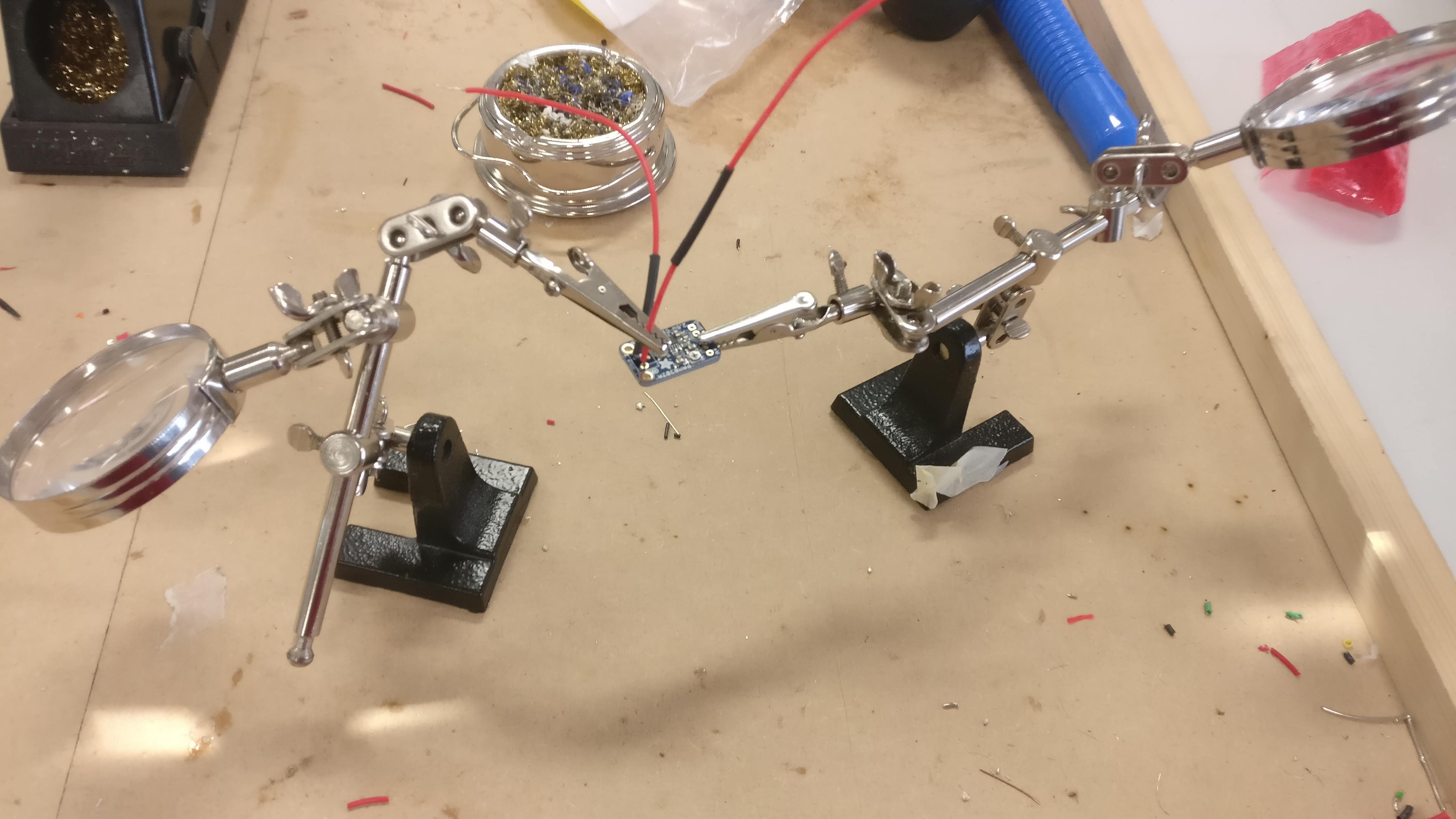
This involved, stripping the micro USB back to its constituent 4 wires ( power, ground, data (positive), data (negative)) and then soldering these back together as can be seen in the attached photos:
![]()
![]()
![]()
*NOTE: Not the best soldering I know...
![]()
-
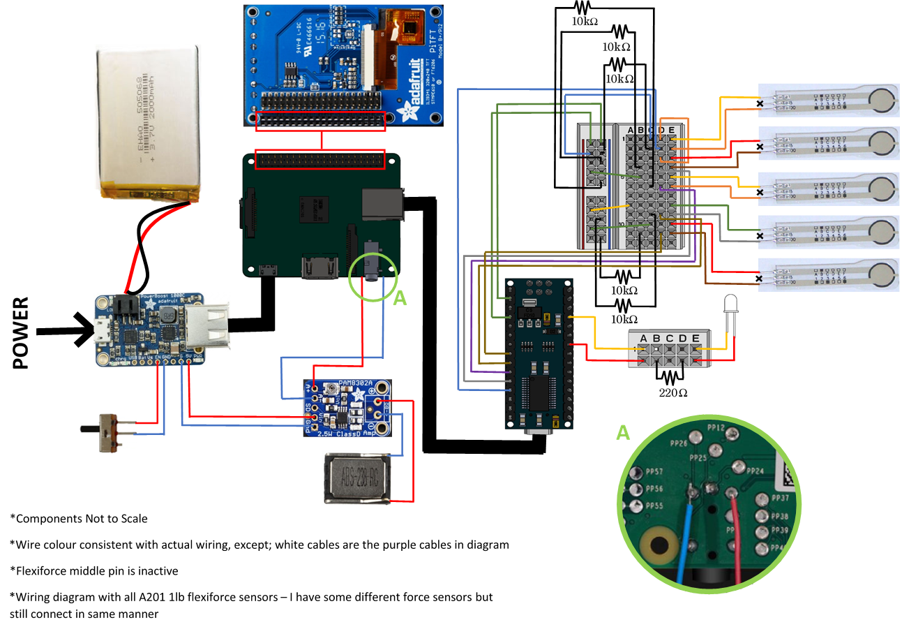
Project Schematic
03/04/2019 at 18:10 • 0 commentsHere's a schematic of all the wiring/set-up of the watch so far:
![]()
-
New Strap
03/04/2019 at 16:47 • 0 commentsNow that I am no longer aiming for a wrist strap sensor location, I have built a simple prototype strap to use with the pi smartwatch in order to wear it on the wrist. This prototype could and may be used to experiment with a strap control method, time permitting.
![]()
This is simply 3 strips of thin pliable leather sewn together along the edges.
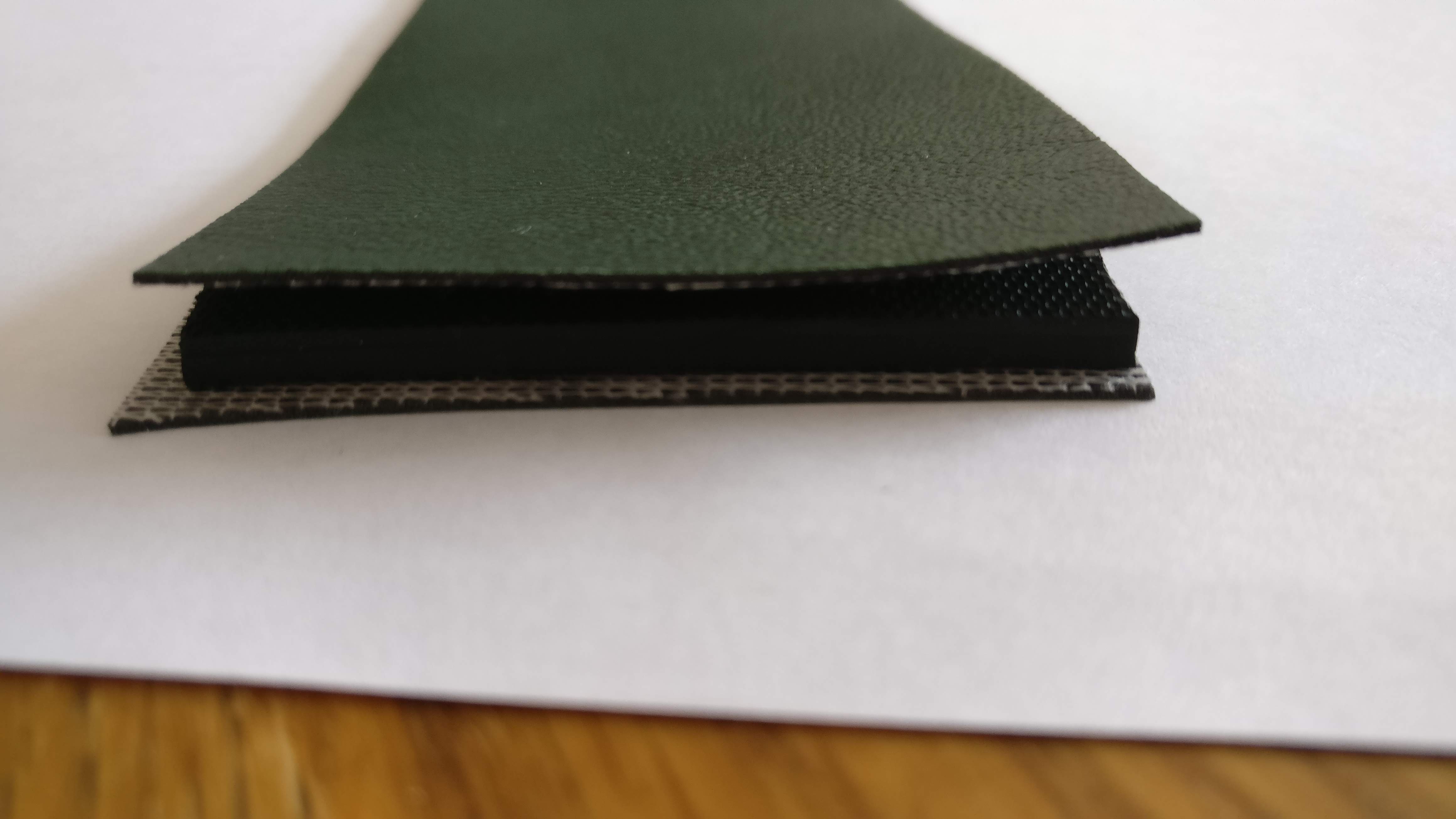
I did originally try 2, with a piece of rubber in-between, like so:
![]()
However, this turned out to be too stiff for good manipulation around the wrist. And too stiff for the hook and loop fastening system I have gone for with this strap design - it would pull itself loose.
-
Multiple Analog Sensors (Arduino)
03/04/2019 at 16:41 • 0 commentsThis project now has 3 FSR sensors connected to the Arduino, with the data being transferred to the Pi. In the end I plan on having 5 in total.
One of the things that cropped up when I started to add more sensors, was the voltage leak between the analog Pins of the Arduino. A common problem I found for alot of people with a fairly simple solution:
http://forum.arduino.cc/index.php?topic=197855.0
Solved by using a 10k phm feedback resistor for each sensor resulted in the minimal voltage leakage between the sensors. Although this did affect the sensitivity of the sensors, as discussed before, changing the feedback resistor can have this affect, it is still sensitive enough - especially for the finger pinching glove method that I am following now.
-
Smartwatch Speaker in Action
03/04/2019 at 16:36 • 0 commentsFollowing on finishing all of the soldering from my last entry, here's a little video of it up and running:
There was no coding needed to get this working after the soldering.
Its very quiet, but that is because the speaker requires a backing board behind it in order to get its full potential. When it comes to designing the case for this watch, I will engineering this backing board into it. So on the final product the speakers work to full affect.
-
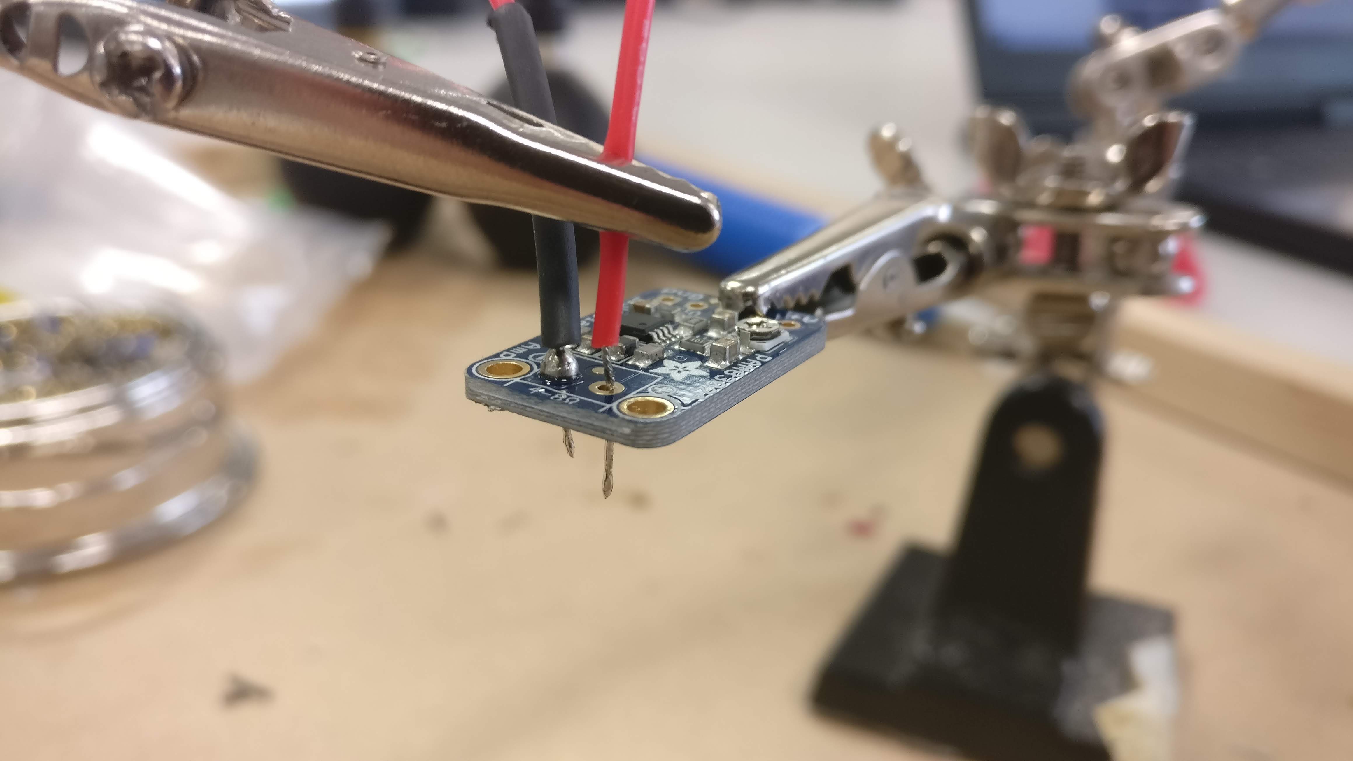
Lil bit of Soldering
03/04/2019 at 16:27 • 0 commentsSo following this gameboy build, only difference is I've moved my project to a Raspberry Pi 3 Model A+ to make this watch smaller. I didn't originally plan on downsizing to the Pi Zero, the smallest available, but after reviewing this guide, I need a board with a headphone jack, in order to hijack the soldering points of it for my speaker.
Does any know of a way, I could have used a Raspberry Pi Zero, with a touchscreen and a speaker system??
But for this project, it will work just fine the path I'm following. Spent the day soldering all of those components together.
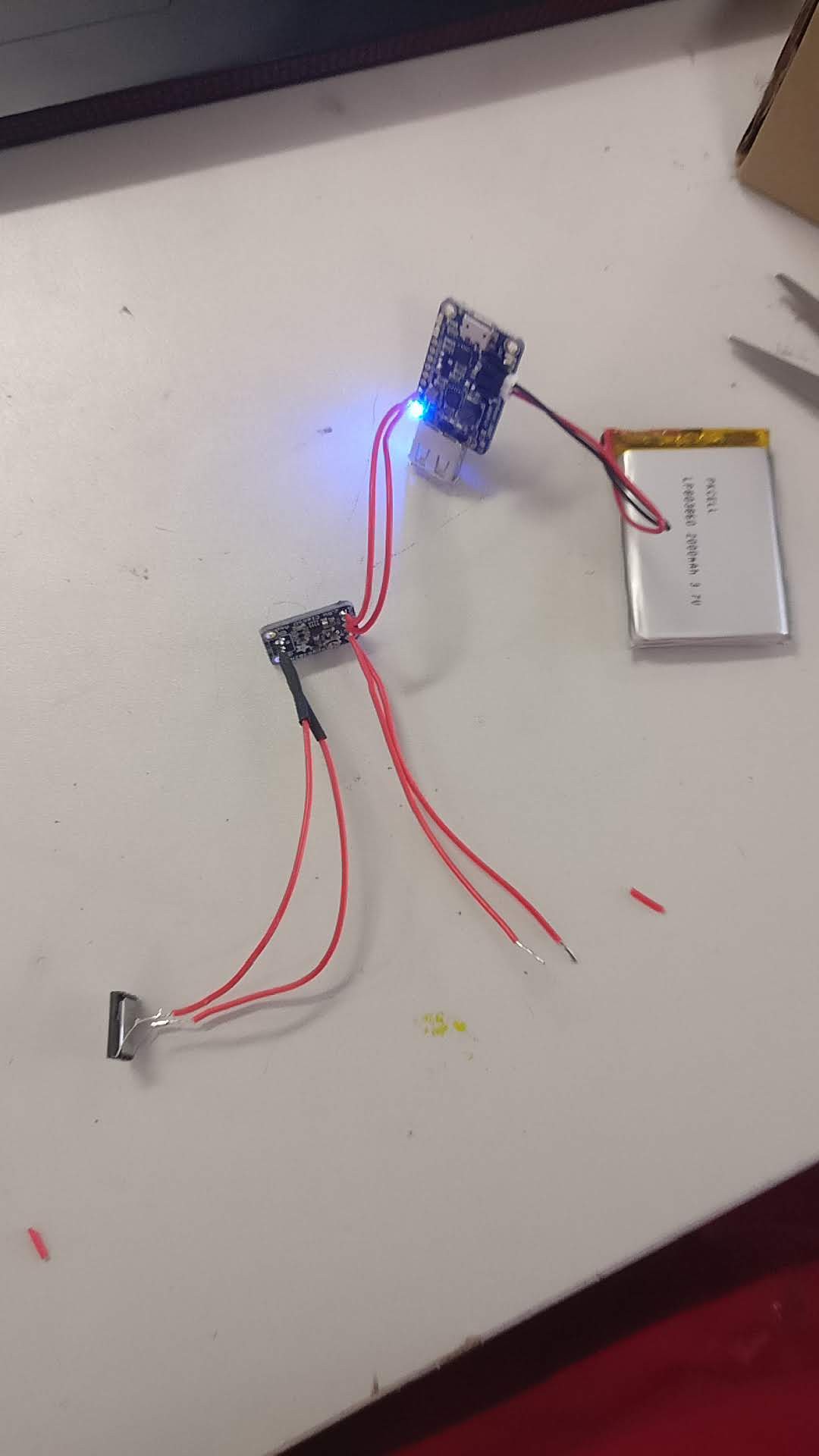
![]()
![]()
![]()
![]()
As you can see from the second last photo, the power from the rechargeable LiPo battery connects to the system just fine. And the final photo, shows the connection of the speaker to the Raspberry Pi, hijiacking the headphone jacks soldering points. All of this is detail in the adafruit gameboy build instructions:
-
Components
03/04/2019 at 16:10 • 0 commentsSo I followed the steps in the adafruit gameboy build instructions:
https://learn.adafruit.com/pigrrl-2/overview
^ This is a brilliant way to bypass the need for using GPIO pins for an audio output.
Is there another way to do this??
Brought these components:
Power Slide Switch [ADA805] - https://thepihut.com/products/adafruit-breadboard-friendly-spdt-slide-switch
PowerBoost 1000 Charger Board [ADA2465] - https://thepihut.com/products/adafruit-powerboost-1000-charger-rechargeable-5v-lipo-usb-boost-1a-1000c
Silicone Wire [ADA1877] - https://thepihut.com/products/adafruit-silicone-cover-stranded-core-wire-2m-26awg-red
Audio Board [ADA2130] - https://thepihut.com/products/adafruit-mono-2-5w-class-d-audio-amplifier-pam8302Miniature Speaker [117-6046] - https://uk.rs-online.com/web/p/miniature-speakers/1176046/
Lipo Battery (2000mAh) [BAT0005] - https://shop.pimoroni.com/products/lipo-battery-pack?variant=20429082247
Now its time to start building...
Gesture Controlled Smartwatch
A larger, more functional smartwatch with gesture controllability