0%
0%
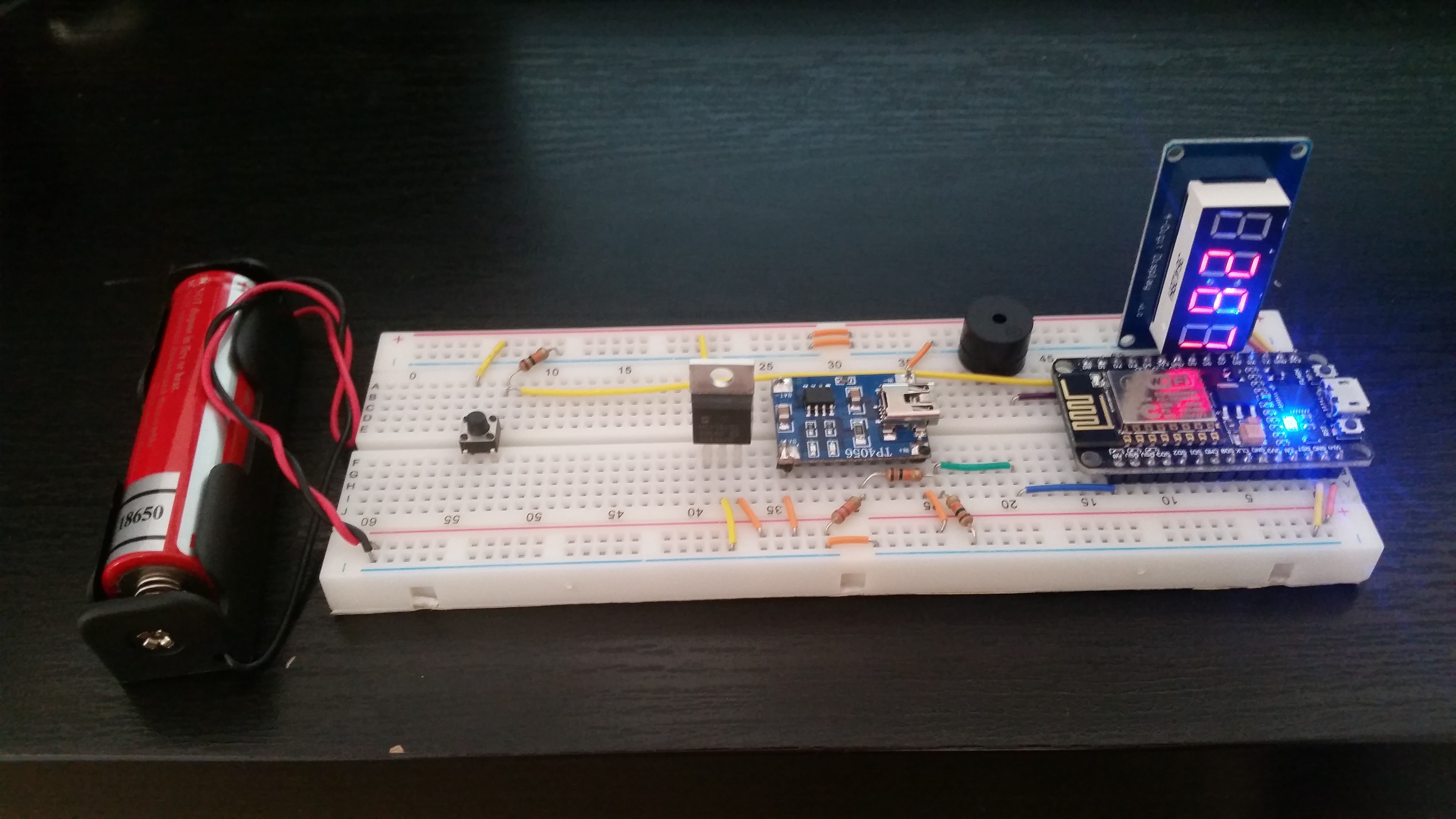
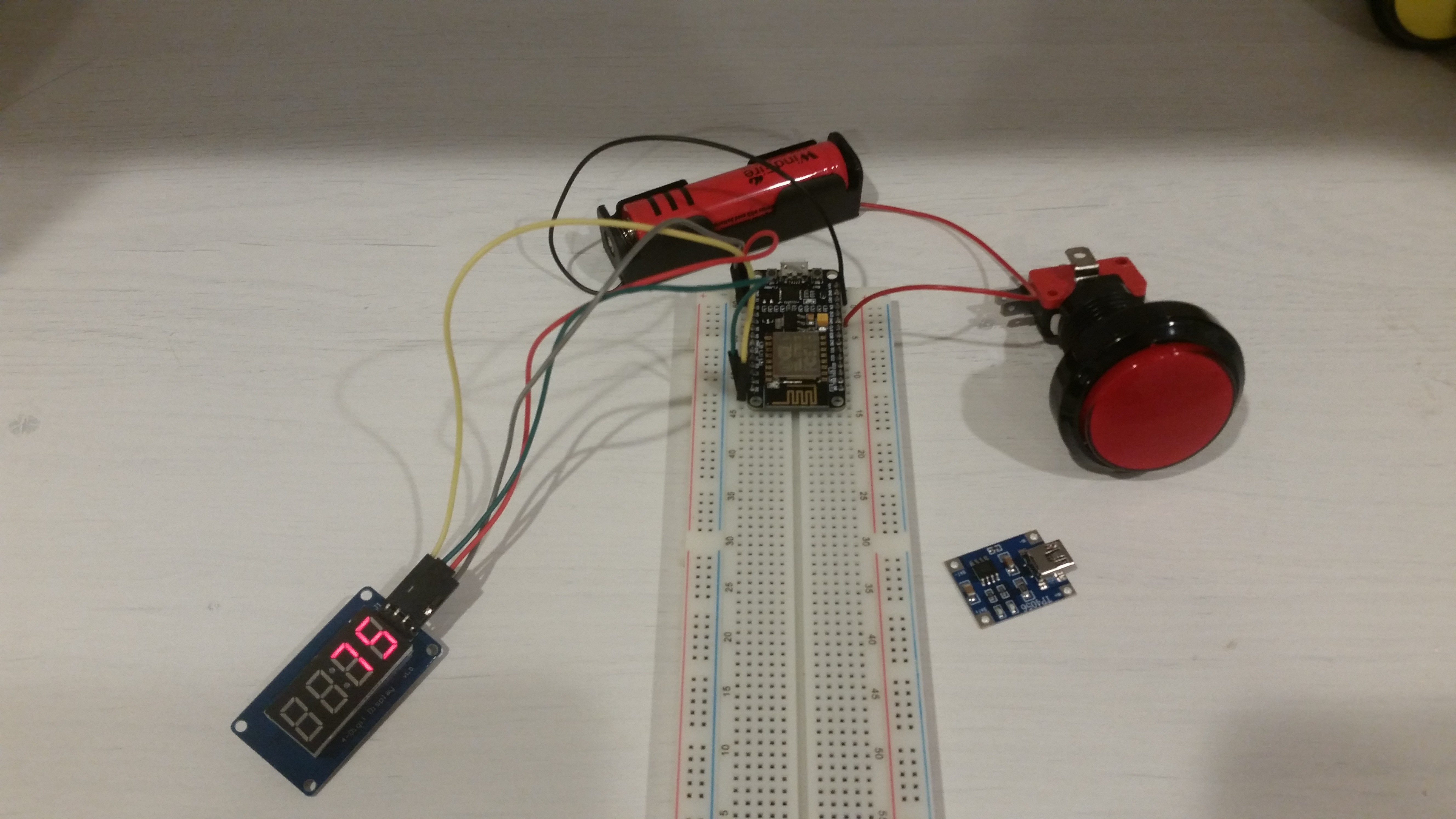
Wi-Fi Game Clock
A Wi-Fi enabled clock that can be used as a time control in chess or other board games for any number of players.
 Patrick Graham
Become a Hackaday.io member
Already have an account? Log in.
Just one more thing
To make the experience fit your profile, pick a username and tell us what interests you.
Pick an awesome username
hackaday.io/
Your profile's URL: hackaday.io/username. Max 25 alphanumeric characters.
Pick a few interests
Projects that share your interests
People that share your interests
 Jeremy g.
 teru
teru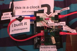
 PointyOintment
 Hulk
Hulk