 Ken Yap
Spurred by interest by readers I finally got off my backside and soldered one board. Then I did an inspection of the joints with a magnifying glass in case there were any missed or bad joints. I did a short circuit test between adjacent pins of the sockets. I also did a continuity test from the IC sockets to the pads. I found one pin bent under the socket. Fortunately I was able to reach under with the soldering iron tip and deposit enough solder to join the bent pin with the pad. Better a little effort now than troubleshooting later.
To start with I will use a 28256 32kB EEPROM so that I can modify the firmware easily. The board also accepts 16kB EPROMs with a change of jumpers.
I have installed a 62256 32kB SRAM. A 6264 8kB SRAM could also be used. The difference is that for the top 2 address pins, A14 goes to NC, and A13 goes to Enable 2, which means that the 8kB will appear at both [0xA000,0xBFFF] and [0xE000,0xFFFF]. So it's just a matter of placing the RAM area the firmware uses in the appropriate 8kB interval.
I have to verify the GAL. I think I used the image for 6.144 MHz crystal but it's easy to burn the right one if I didn't.
Instead of using a MAX232A RS-232 level converter chip, I have elected to use a USB to TTL converter, readily available for a dollar or two. So I have soldered leads directly to the appropriate holes of the MAX232A.
The RAM backup is optional and won't be used.
I soldered a two pin header for the reset pins to which I can plug a lead to a NO push button switch.
Instead of using a barrel connector for power, I have soldered power supply leads. I don't understand this obsession with barrel connectors for 5V power. A more logical choice would be a micro USB connector which can take a cable from a 5V USB power supply. Many people have spare phone chargers which can be turned into project power supplies. Did you know that micro USB connectors are rated for a large number of insertions, think of all the times people plug their phone to charge, so are quite sturdy?
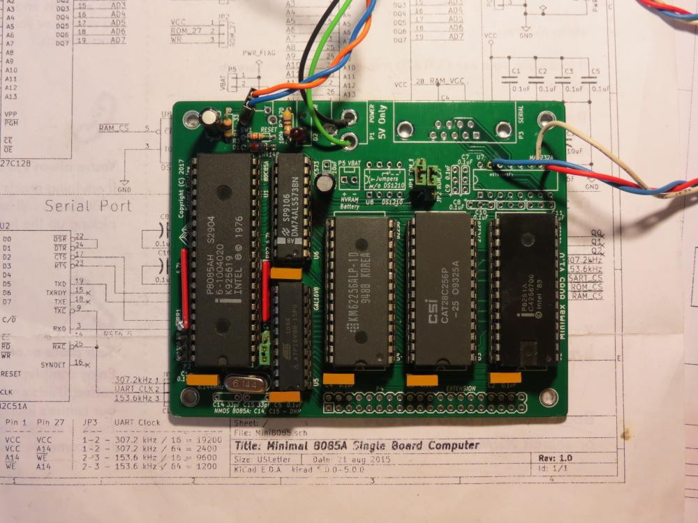
Look at the age of those chips! So now I have to work up the courage to connect up a LED, fetch the blink program, burn it into the EEPROM, and power up.
Discussions
Become a Hackaday.io Member
Create an account to leave a comment. Already have an account? Log In.