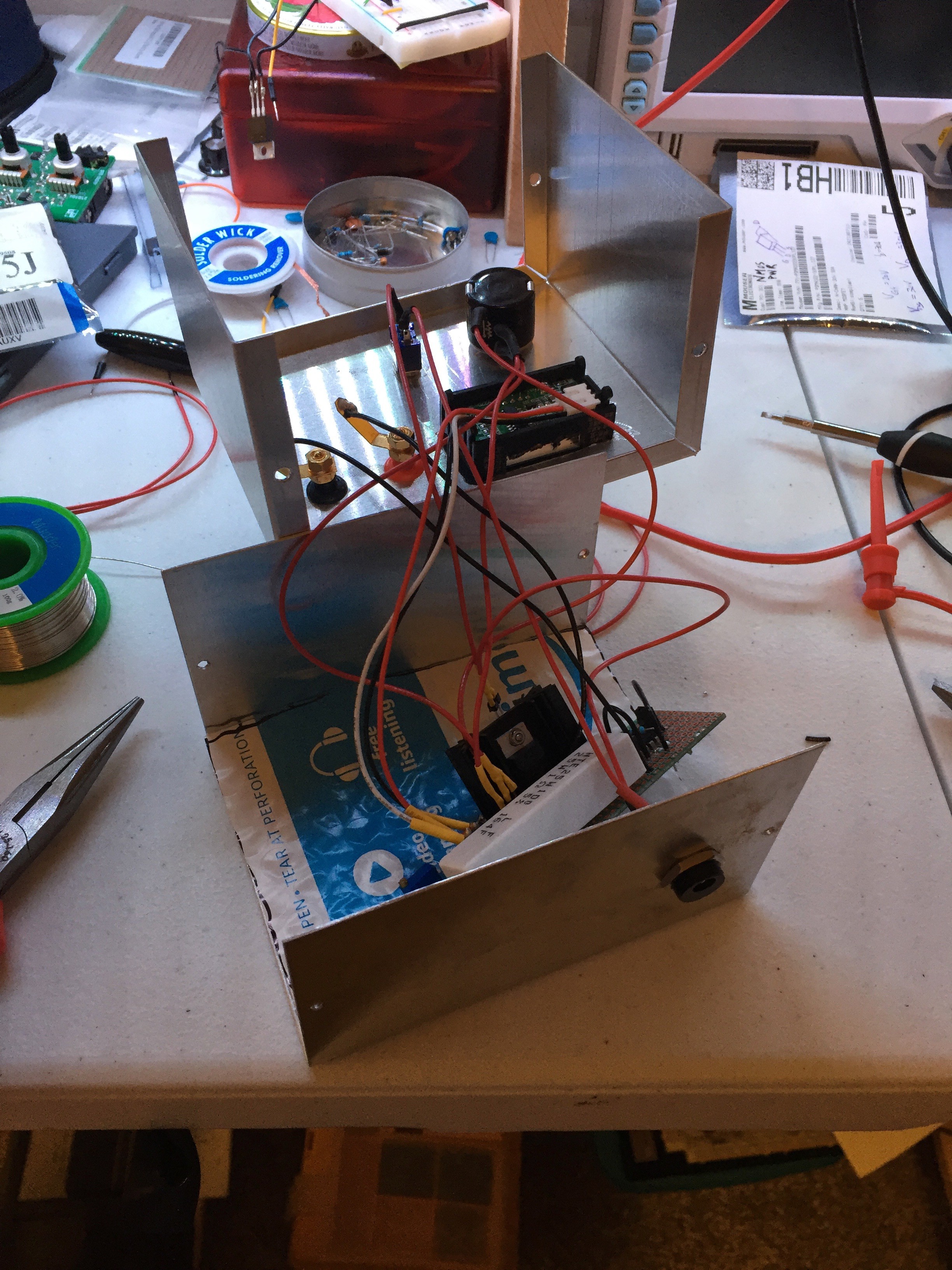
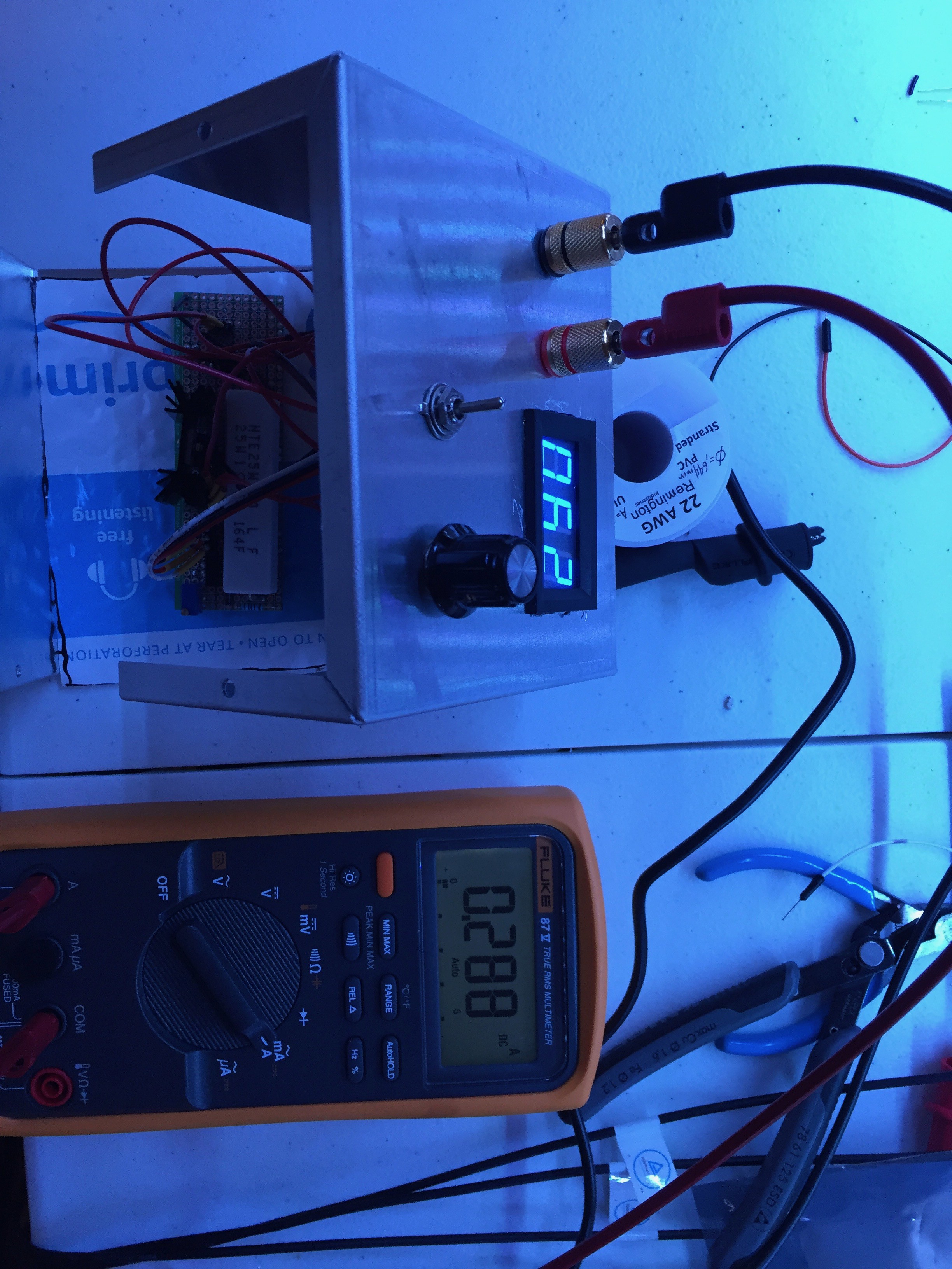
• Assembling the Load

    Grant Giesbrecht03/02/2019 at 22:12 0 comments

    I received the final parts I needed to build my load. I started off by putting the actual circuit together on a piece of strip board. It's a small circuit, so it didn't take too long. I made sure to connect all parts that mount to the chassis with plugs rather than soldering their leads to the PCB so maintenance and trouble shooting would be easier. Getting in the tight nooks and crannies of an aluminum enclosure can be a pain, so I wanted the board to be easily removable. The only exception were the binding posts. The load is designed to take up to up to about 4 amps, so I didn't want that much current running through the header pins I was using to connect the other components to the PCB. Here's an image of the finished PCB installed in the aluminum enclosure.

    I used a drill and my Proxxon rotary tool to make holes in the enclosure for the power jack, switch, potentiometer, binding posts, and volt meter. The bottom of my PCB has lots of exposed nickel plated copper wires, so cut a piece of a bubblewrap mailing envelope to make an insulating layer on which my board can rest. 

    I ran into a ton of issues while testing my board. First I found that the op amp used in my ground-generating circuit was fried. Fortunately, it was a dual channel amp with only one channel being used, and the unused channel wasn't fried, so it was pretty quick to switch over to the operational channel. I also ran into a problem where the FET was shorting the drain to ground because the drain was connected to the heatsink, which was shorting to my ground rail. This took me a while to catch. 

    After I worked out all of the kinks, the load worked pretty well. I used my Fluke 87 to calibrate the volt meter. It was easy to do because I had the op amp U3 hooked up as a variable gain amp. By trimming RV2 I could set the gain to get accurate readings on the load's panel meter. The meter's reading still isn't perfect though. It's accurate within about 20 mA. 

    The only thing I don't like is how hot my MOSFET gets. I looked at the inside of my load with my FLIR after running about 1A at 10V through it for 2-3 minutes. The FET and its heatsink were getting up to about 120 C and rising. I really need a larger heatsink, and cutting some slits in the enclosure and adding a fan is probably a good idea also. I'll add a larger heatsink when I have the chance, but I'm going to skip the fan because that's more effort than I want to put into this project right now. Instead I'll just be sure to run the load for brief periods of time and give it long breaks to cool down. 

  • Testing the Load on a Breadboard

    Grant Giesbrecht02/26/2019 at 08:20 0 comments

    I threw the circuit together on a breadboard to: 1.) make sure it was working 2.) use for another project (I needed the load for another project pronto and some critical parts for the load's "final form" are in the mail).

    After getting the circuit hooked up correctly with all-working parts (a fried op-amp caused some troubles initially), it worked quite well. I still need to implement the amplifier which adjusts for the source resistor not being exactly 1Ω, but this is good enough for what I need immediately. 

    One of the parts I'm waiting on is a TO-220 heatsink, so I had to improvise. Sure I didn't have any heatsinks lying around, but I did have an altoids tin. I filled the tin up with water and submerged the MOSFET. Sure this is kinda ghetto, but it worked pretty well. I hit my improvised heatsink with my FLIR thermal camera and it showed that the water was keeping the FET sufficiently cool and that the water was warming up too, so the sink was taking significant heat from the FET. Aside from a little electrolysis I saw occurring around the leads, it worked swimmingly. Turns out a spot of water is a pretty effective heat sink in a pinch. 

    Excuse the image of an image, but my thermal camera can't save images. 

    I read the current with my fluke 87 and looked at the set point with my second meter. They didn't quite agree, but that's expected because I haven't installed the calibrating amp yet. I'm going to wait for the final PCB to do that.