 Grant Giesbrecht
I threw the circuit together on a breadboard to: 1.) make sure it was working 2.) use for another project (I needed the load for another project pronto and some critical parts for the load's "final form" are in the mail).
After getting the circuit hooked up correctly with all-working parts (a fried op-amp caused some troubles initially), it worked quite well. I still need to implement the amplifier which adjusts for the source resistor not being exactly 1Ω, but this is good enough for what I need immediately.
One of the parts I'm waiting on is a TO-220 heatsink, so I had to improvise. Sure I didn't have any heatsinks lying around, but I did have an altoids tin. I filled the tin up with water and submerged the MOSFET. Sure this is kinda ghetto, but it worked pretty well. I hit my improvised heatsink with my FLIR thermal camera and it showed that the water was keeping the FET sufficiently cool and that the water was warming up too, so the sink was taking significant heat from the FET. Aside from a little electrolysis I saw occurring around the leads, it worked swimmingly. Turns out a spot of water is a pretty effective heat sink in a pinch.
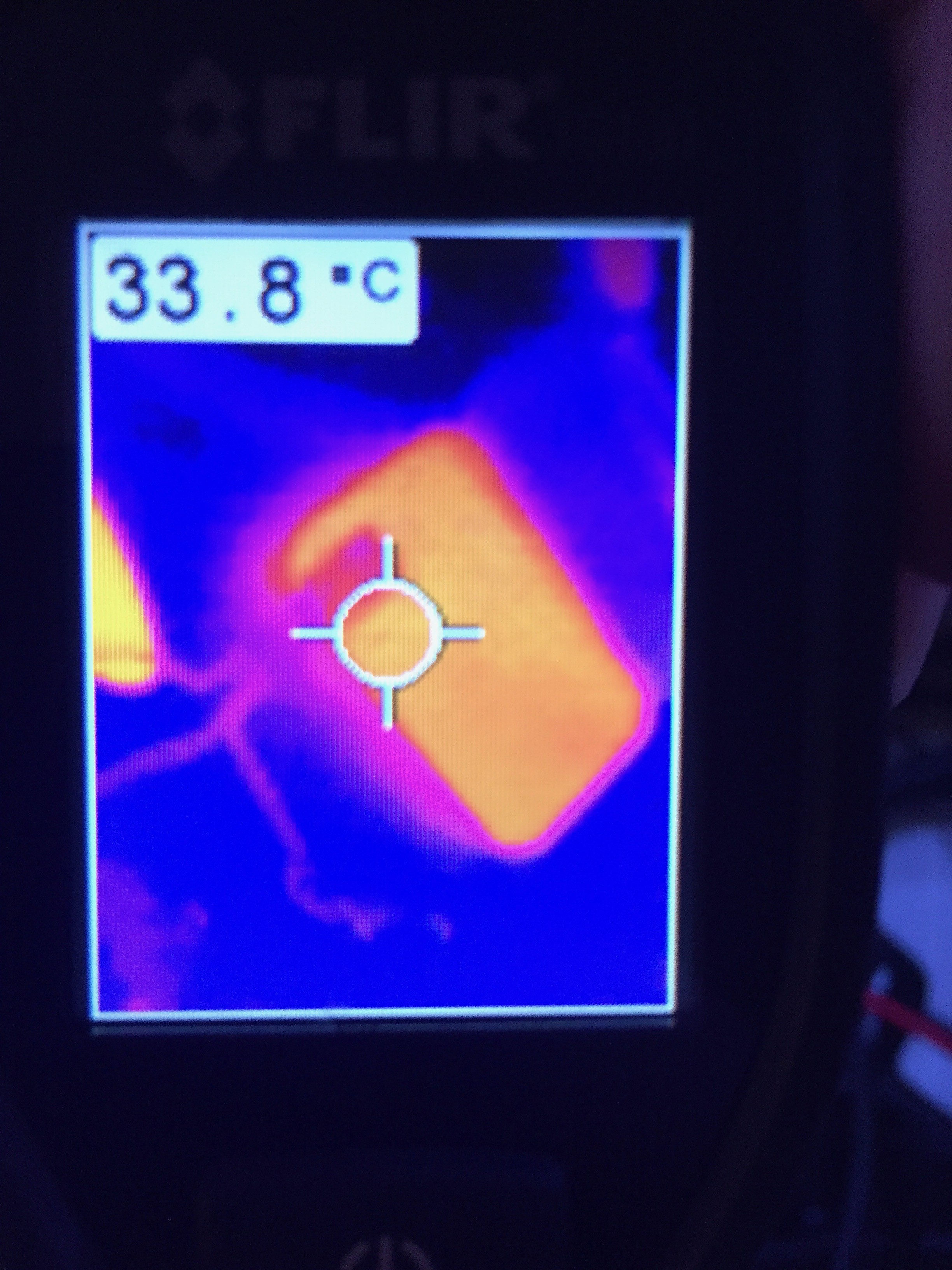
Excuse the image of an image, but my thermal camera can't save images.
I read the current with my fluke 87 and looked at the set point with my second meter. They didn't quite agree, but that's expected because I haven't installed the calibrating amp yet. I'm going to wait for the final PCB to do that.
Discussions
Become a Hackaday.io Member
Create an account to leave a comment. Already have an account? Log In.