Hello again! I'll be reviving this project with a new, hopefully improved printer design.
The new design is no longer a bed-slinger, has a 100x100x130mm build volume, is overall sturdier, and has a host of design changes that allow more general electronics selection.
I'm currently testing a prototype of the new printer. It has some design flaws, namely the rack/pinion sizing, but can produce reasonably accurate prints in its current form (Though at limited speed).
I've attached some images of the printer 3D model as well as of the current prototype. Over the next few weeks I expect to post the first fixes to the current design problems, and I'll post project updates as I test them.
Current problems:
- racks on each axis distort during operation (add rack rigidity/change pressure angle)
- excessive/unrepeatable backlash (add adjustability for pinions)
- z-axis binding (working on altered z-axis design)
- extruder lever can get "caught" and not apply pressure properly
- no cooling fan!
I won't be releasing the 3D model/lasercutting files juuust yet, as I don't feel it could be considered functional in its current form. Once I've worked through the motion issues in the list above, I'll release a reliable version.
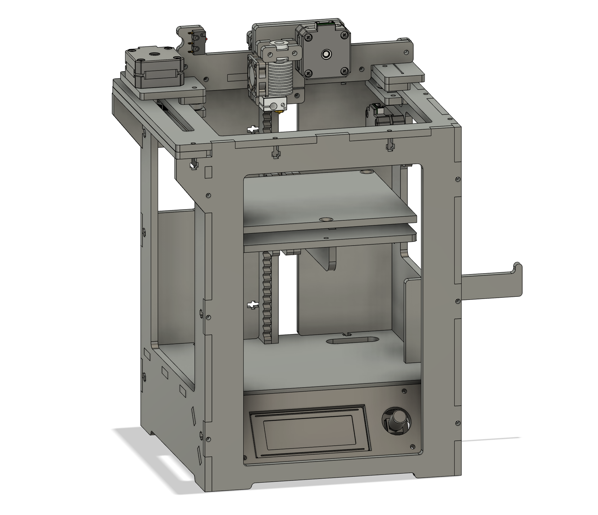
Full 3D model
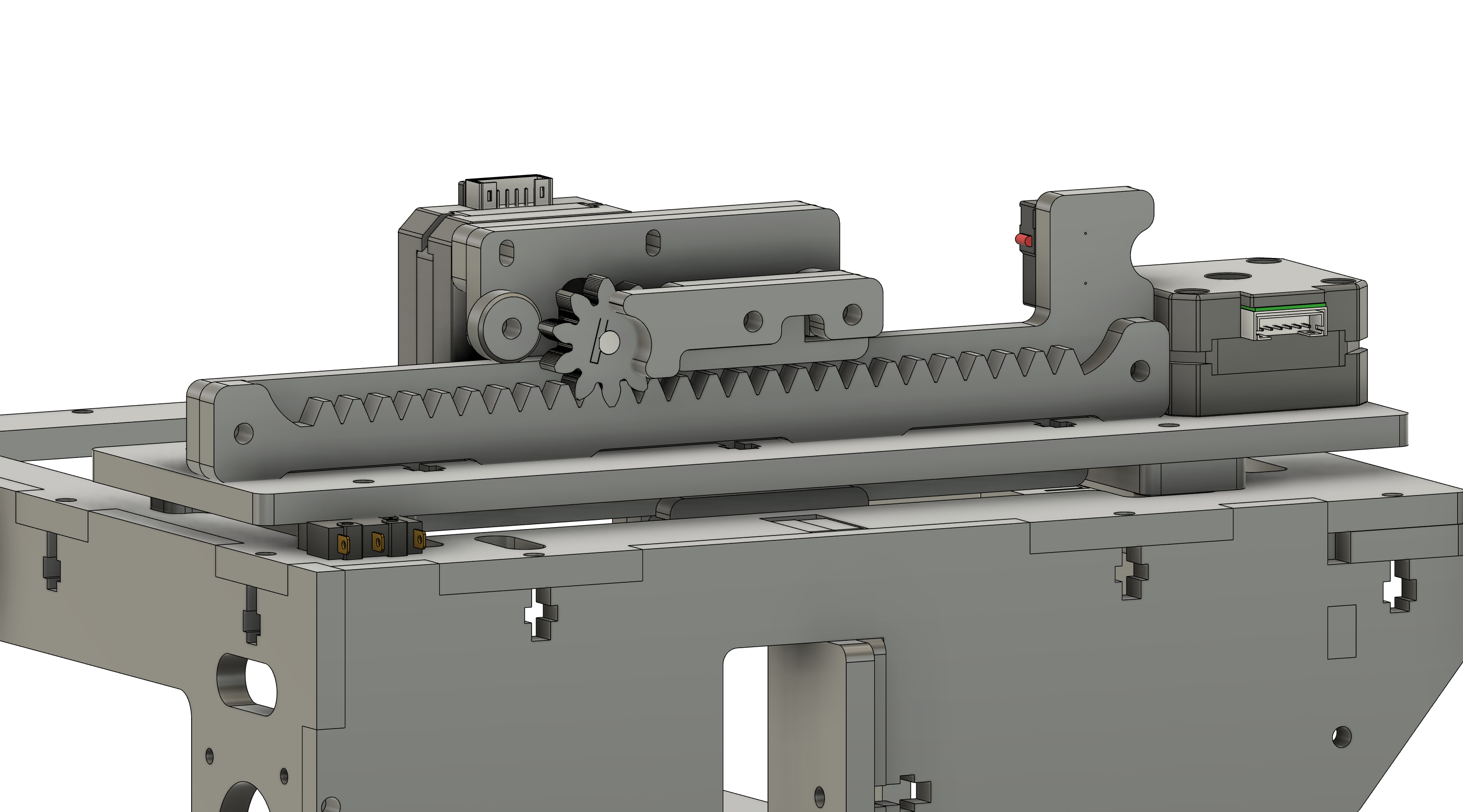
x-axis rack/pinion
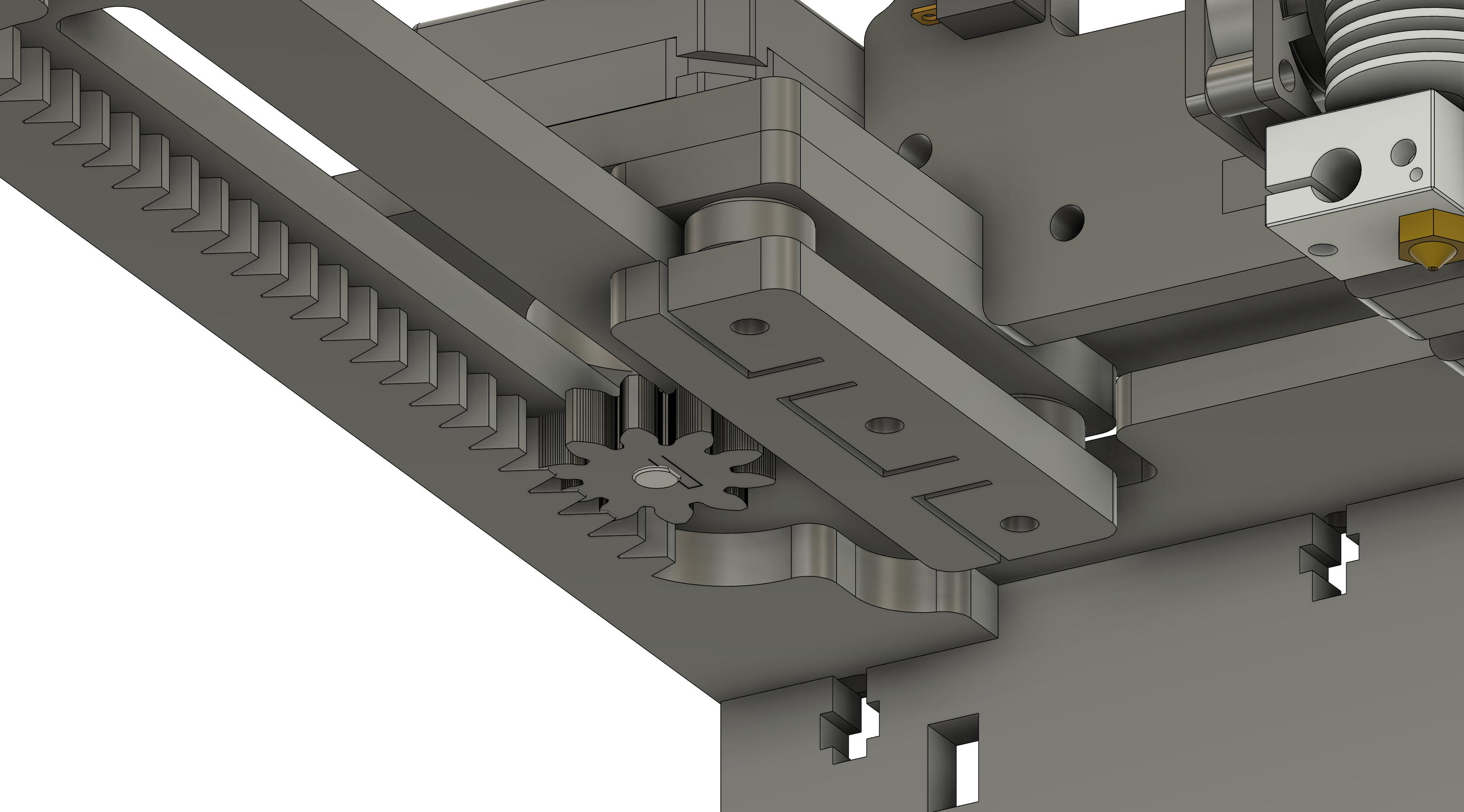
y-axis rack/pinion
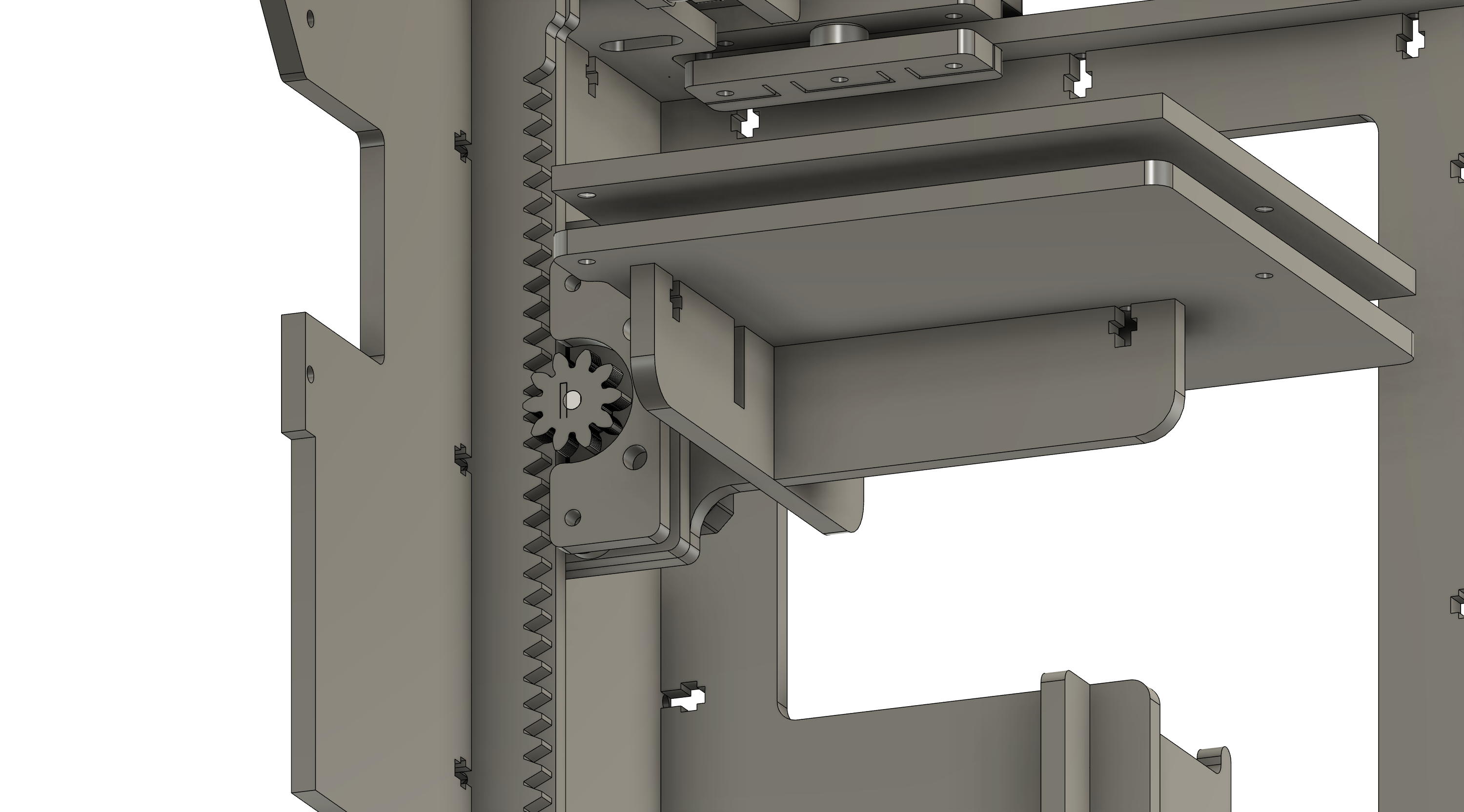
z-axis rack/pinion
Lasercutting assembly

OLD DESIGN
This is hopefully the final frame update.
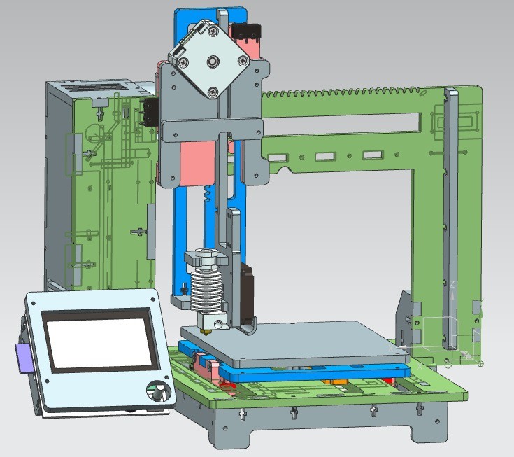
Here's the full 3D model:
The printer is a modified prusa-style system, with the Z axis riding on the X axis, and the Y axis actuating the bed.
The frame relies on M3 x 16mm bolts for almost every connection, with 4 M3 x 50mm bolts connecting the Z axis to the X axis, and a handful of M3 x 25mm bolts for the roller assemblies. The rollers used for each axis are a simple lasercut ring around a 6mm tall by 7mm outer diameter nylon spacer with 2 washers on either end. Here's a quick view:
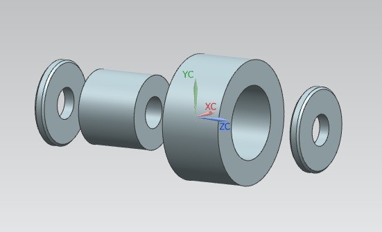
The roller system also requires several eccentric spacers, which can be printed in just a few minutes. These eccentric spacers press the rollers into the rails of each axis and ensure smooth rolling action. The whole motion system relies on these rollers, and so far they've been performing well. I've only tested them for around 20 hours of printing, so I'm still waiting to see if or when the rollers wear down over time.
The motion system:
Lets go through how each axis works, starting with the Y axis.
The Y axis:
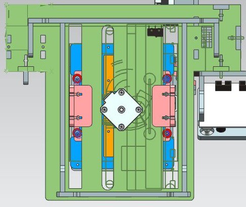
Here we can see the bottom of the printer and the Y axis mechanism with major components highlighted. The Y axis stage is blue, the roller bearings are red, the slide bearings are pink, the rack is orange, the base of the printer is green, and the eccentric spacers are in purple on the right side of the stage.
The slide bearings and the roller bearings are attached to the bed of the printer and ride along the two rails. The slide bearings constrain the bed in the Z direction, and the roller bearings constrain the X and Y directions. The rack engages with an 8 tooth, 5mm diametric pitch gear mounted on the output of the stepper in the center.
In the video below you can see the Y axis moving:
I've found that the surface finish of plywood is a less than adequate bearing surface, and the axis will bind if left unsanded or bare. Since hand-sanding the rails can introduce bowing or other inconsistencies into the surface, I've found the easiest option is to throw some low-friction tape on either the rail itself or the bearings for each axis. So far I've tested regular scotch tape, kapton tape, and packing tape, and all have worked well.
Even better, if you have access to a planer, I've found that planing the wood down to 5.7mm before lasercutting is the best option, and makes assembling the printer much easier. I'll put out a video near the end of the summer on my process for planing the wood I use.
The X axis:
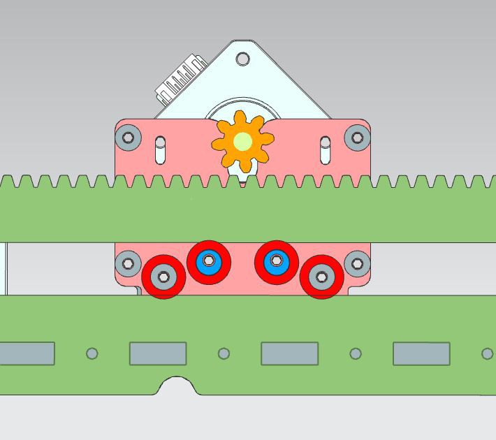
Here we can see the interior of the X axis carriage, with the roller bearings in red, the rear slide bearing in pink, the eccentric spacers in blue, and the rails/rack in green. The front slide bearing is another important component but is not shown, as it it shared by the Z and X axes and obscures the X mechanism.
The rollers ride on the inside of the frame, constraining the carriage in the Z direction, while the front and rear slide bearings are pressed against the rails and constrain it in the Y direction. The top rollers contain the eccentric spacers for this axis,and press against the top rail to stabilize the axis.
Here's a video of the X axis moving.
Here we see the top of an old version of the X/Z carriage. The Z axis rides on the front of the X carriage, and the front slide bearing can be seen sandwiched between the two. The X axis rollers sit in the middle of the moving assembly, so its hard to show, but they're about a centimeter below the horizontal rack.
This old version of the Z axis was redesigned because the thin vertical rack warped while moving. The new version of the Z axis is described below.
The Z axis:
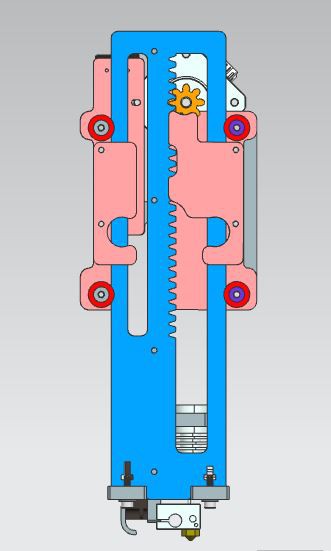
The first photo below is the Z-X carriage from the back, and shows how the Z axis mounts to the front of the X carriage.
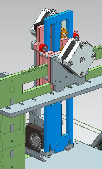
The photo shows the interior of the Z axis mechanism. The main axis is in blue, the slide bearings are in pink, the pinion gear is in orange, and the eccentric spacers are in purple on the right side. The front slide bearings are shared with the X carriage, and the entire mechanism is pinned to the X carriage with 4 60mm M3 bolts.
Here's a quick video of the (old) Z axis moving.
The lasercutting files:
Figuring out how to fit this many parts in 3.4 square feet felt alot like a bad tetris game.
The first cut, 12 inches by 20 inches.
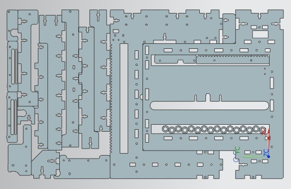
And the second cut, also 12 inches by 20 inches.

And that's the whole printer frame! Both of these files can be found below, and can be cut from any suitably strong 6mm material.
I'll be putting together a lasercutting/prepping/build video at the end of the summer, as I'll be travelling until mid-August. I'm also working to put together an organized release of the 3D models, but I haven't had time to sit down and convert the ~60ish .prt files to something more useful. It might still be a while, but I promise they're both coming.
Thanks for checking out my project! If you have any questions, comments on the design, or anything else, you can email me at lukewallac@gmail.com.
(most recent file update: 2019-07-31)