There's been a huge improvement in print quality since I got the backlash compensation algorithm running. Test print number 8-ish looks pretty good! I'd caution even acceptable.
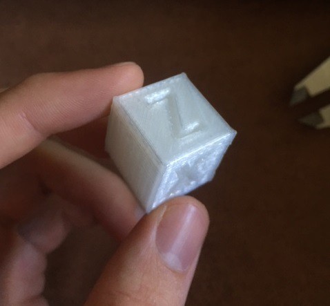
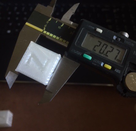
The y-axis is now much closer to 20mm than without compensation, so I'd say that the algorithm is working!
The backlash compensation software isn't actually too complicated. It's just a python script that I run the gcode files through before printing, and it adds quick G0 moves that take up the backlash before every direction change. Right now it is a separate program from the printers software, but in the next update I'll be dealing with placing it inside Marlin 1.1.9 to run before every print.
The compensation moves can be seen if you load the altered gcode files in Pronterface.
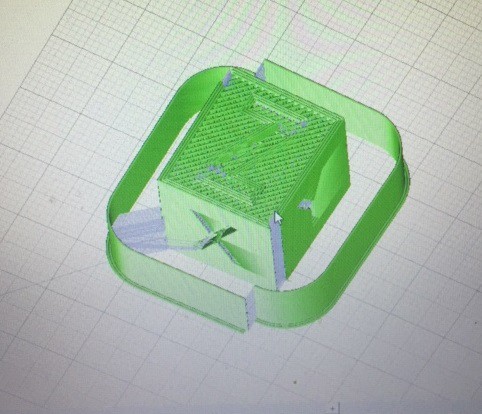
In the picture above, that 'split' in the line around the cube is due to the compensation moves that the script added. Here the script is only running for the Y axis, as the backlash in the X and Z axis is unnoticeable. But if the other two axis had significant backlash, we would see similar splits on the left and right sides as well as the front and back. For context, the backlash in the Y axis is ~2.3mm and the backlash in the X axis is ~0.2mm.
I should add that the Y axis only has this much backlash because I've put off upgrading the Y axis rack and pinion to test the compensation. Once I've finished testing I'll install the new rack and pinion and the backlash will be much closer to the ~0.2mm of the X and Z axis.
Now here's how the compensation algorithm works:
To determine the amount of backlash in each axis, I measured the backlash in each axis and entered the measured values before running the script. In the next update, I'll be dealing with using the endstops to determine these values instead.
Once we have the backlash values, we need to determine where to place our compensation moves. To do this, the script splits the gcode files into three lists; all lines containing X moves, all Y moves, and all Z moves. It then iterates through each of these lists and determines the direction of the printhead at each line. To do this, the script compares concurrent pairs of moves, subtracting the current position from the last position and storing the sign of the remainder. ( either +1 or -1 )
This creates three new lists with a negative or positive value for each line. The script then iterates through these three new lists and compares pairs of lines. If the sign of the current line differs from the sign of the next line, that means the printhead has switched direction at that line.
For example, if the list was, [ +1, +1, +1, -1, -1, -1, +1, +1 ], a direction change would occur at line 3 and line 6, where the list flips signs.
The script then stores every line that contains a direction change, and uses the inputted backlash values to generate and insert a compensation move at those lines.
Here's a screengrab of a gcode file with a Y axis compensation move inserted. The lines starting with G1 are print moves, and the lines starting with G0/G92 are inserted by the algorithm.
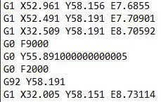
You can see from the first two lines that the Y axis is moving in the +Y direction, as 58.191 (line 2) - 58.156 (line 1) = 0.035, which is a positive value. So the first value in this direction list would be +1.
Next, the algorithm ignores lines that have 0 difference between them, so line 3 is ignored (Y58.191 - Y58.191), and Line 4 - 7 is the compensation move, so the next Y move it would compare is the last line. Comparing the Y component of line 8 to line 2, we get 58.151 - 58.191 = -0.04, a negative number. Therefore the next value in our direction list would be -1. This indicates a direction change, as the two direction differ in sign.
When the algorithm compares the direction list for this portion of the file, it will see that the direction flipped at line 3, and will insert lines 4 - 7 as compensation.
The first compensation line, "G0 F9000" sets the movement speed, 9000mm/min.
The next line, "G0 Y55.89..." is the actual compensation move. You can see that it is ~2.3mm less than Y58.191, as this was the measured Y axis backlash, and that it is in the direction of the next move, -Y.
The third line resets the speed to a slower value, 2000mm/min.
And the final line, "G92 Y58.191" resets the Y axis position to the same as line 3, so the printer doesn't think it moved at all.
The backlash has now been removed, and the print can continue on. :)
Below is a video of the Y axis rack and pinion. If you watch the pinion gear you can see it jump backwards to press into the opposite side of the teeth before each direction change.
For the next update I'll be working on making sure the algorithm works for curves and other more complicated gcode moves, as well as automating the compensation process and placing the code inside of Marlin to run when a print is selected. Thanks for reading!
Discussions
Become a Hackaday.io Member
Create an account to leave a comment. Already have an account? Log In.
If you used something like Machinekit, backlash compensation is built in and just a number. :) A side effect of the work done for the #P2 - Pick and Place for 3D Printers could be a PocketBeagle RAMPS cape, so that could be an option... :)
Are you sure? yes | no