Kris Winer
The intent is to install the device once and have it be in autonomous service for two or three years. There is not a specific design goal here other than to minimize average power usage, size, and cost. In reality, it will be easier to minimize power usage and size than cost, but the "finished" devices should end up costing about $25 each with the cost dropping rapidly as production volumes increase.
There are practical benefits to small size. The device is more likely to fit into a wider size range of bins, the device is unobtrusive so less likely to be noticed by curious malefactors, the device is less likely to "interact" with the contents of the bin, etc. The reasons for low average power usage are obvious--smaller battery and/or longer battery life. The methods to get there are not. Let's start with the sensors.
We don't necessarily need all of the sensors mentioned above in every application, but it is useful to consider the case where we do. We need to detect and monitor bin level. We need to monitor temperature and humidity inside the bin in the case the contents are organic. Such cases include garbage bins, hospital waste bins, recycle bins, etc. We would like to know when the bin lid has been opened or has been left open, and we would like to know if the bin has been jarred or tipped over. What sort of inexpensive, low-power sensors could do all of this?
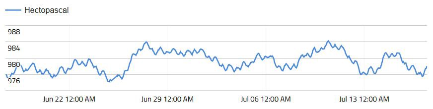
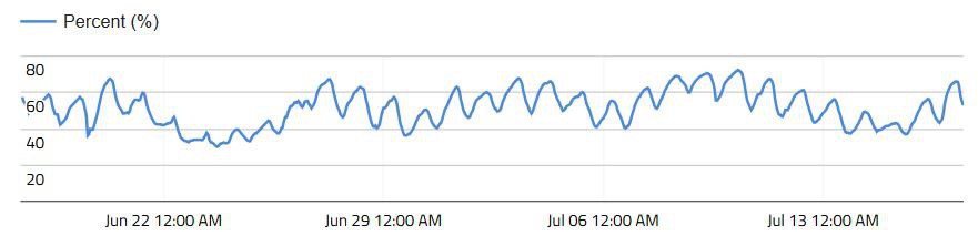
The ~$4 Bosch BME280 (or BME680 in case air quality must be monitored, but this is not an inexpensive or low power sensor) measures temperature, pressure, and humidity. It has a forced mode, meaning the sensor wakes from low power (~1 uA) sleep, takes one measurement, and goes back to sleep upon a single command. Since all of the data we want changes very slowly (with the exception of the light level when the lid is opened) it makes sense to use a timer callback, in my tests every ten minutes, and in the callback the BME280 simply makes one measurement each of temperature, pressure, and humidity. At this duty cycle the power usage is between 1 and 2 uA.
The ~$1 Vishay VEML6040 is an ambient light sensor with four channels, R, G, and B as well as a broadband "white" channel which can be used to estimate IR. The VEML6040 has a standby current of just 0.8 uA and uses 200 uA when in measurement mode. Similarly, there is a forced mode but I have simply been doing this manually; enabling the sensor, reading the sensor for 40 ms (shortest integration time), and then disabling the sensor. This mode of operation uses ~8 uA. The problem is the VEML6040 has no interrupt. Ideally we would like to set a light threshold, have the sensor monitor the light level and wake the MCU when the threshold has been crossed. The purpose of the light sensor in this application is to detect when the bin lid is open. In normal use this occurs irregularly and for only a brief period. So in order to capture this we would have to run the VEML6040 in a continuous mode which would cost a lot of power for little benefit. So we might have to limit its use to detecting when the lid is left open or just not use this sensor at all. An interesting possibility is whether the pressure sensor variations could be used to detect lid opening and closing. This would strengthen the case for dropping the VEML6040.
And of course, there are cheaper and lower power photodiodes for light detection like the $0.50 0805 SFH2716 that would likely be better anyway for this application (what was I thinking with the VEML6040!?). This diode generates ~0.5 uA at 1000 lux (bright sunshine is 20 klux) so the circuit would use a 500 K resistor in a divider circuit to detect when the bin inside is dark (V ~0 V) or light is available (V ~2 V). The divider would be read by a host analog (ADC) GPIO . This circuit costs almost no power since when dark the photodiode resistance is many GigaOhms. The STM32L082 ADC can be configured as a comparator and trigger an interrupt when the voltage...
Read more »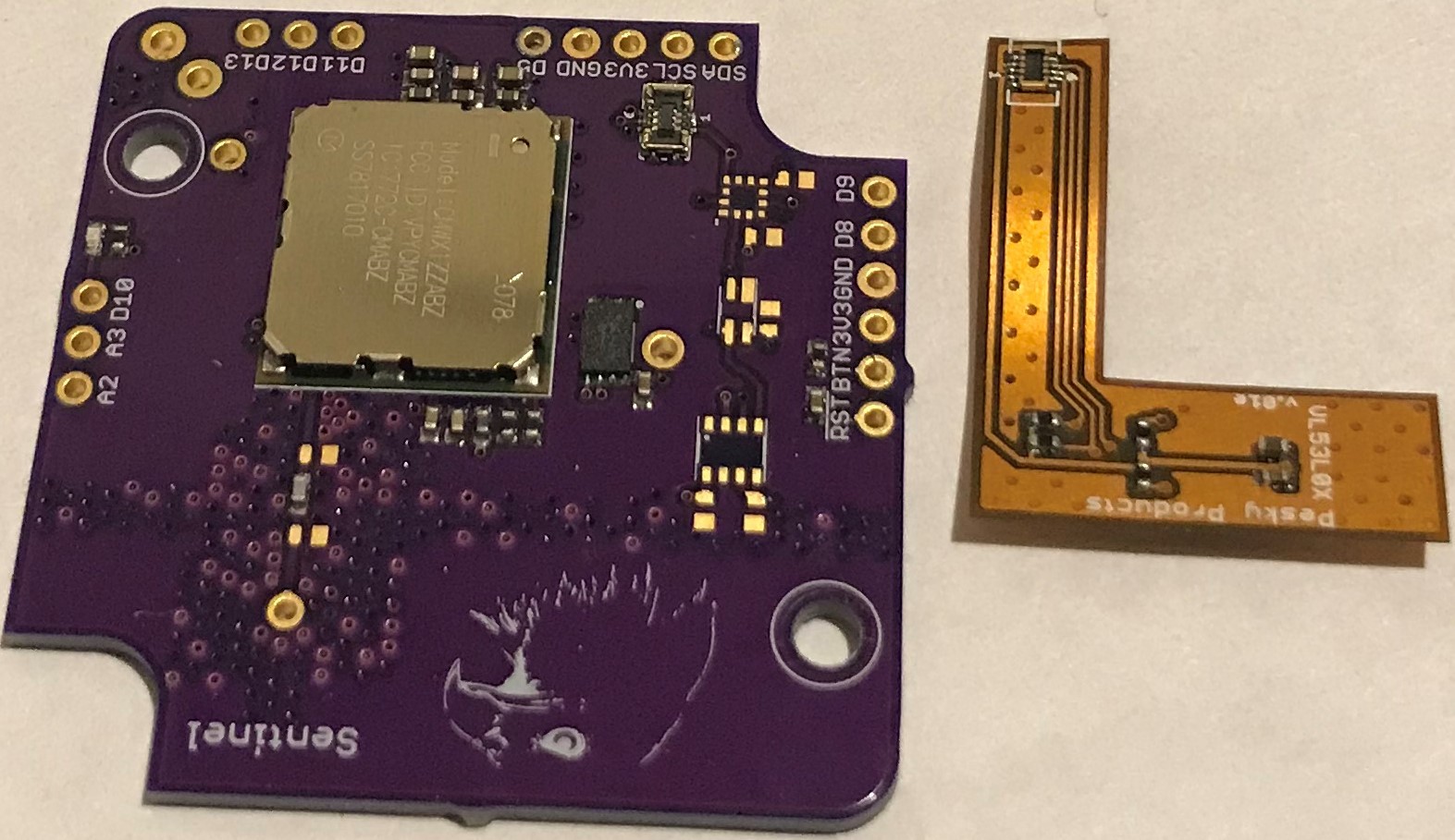

 the Bin Level Monitor is still chugging away. Next update in a week.
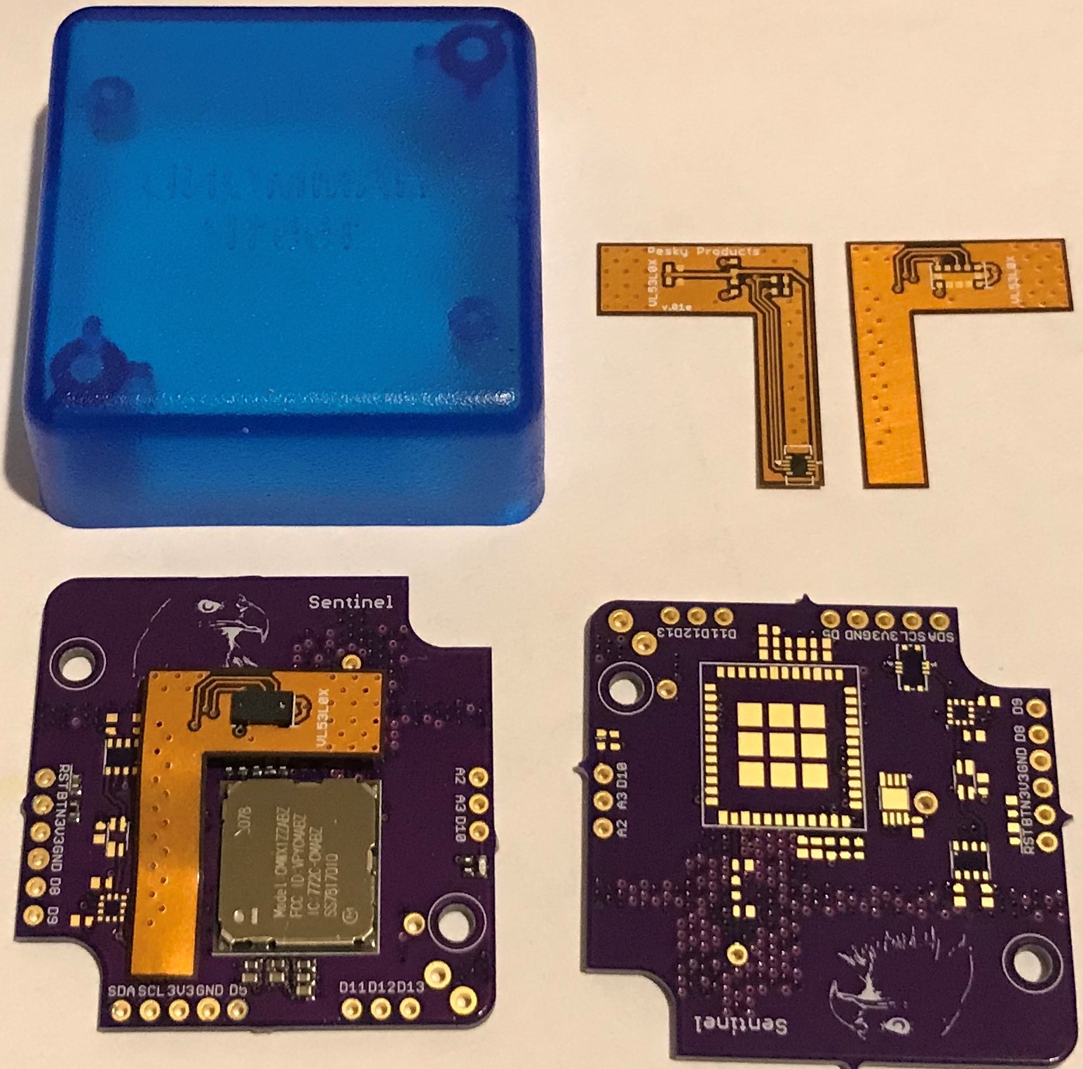
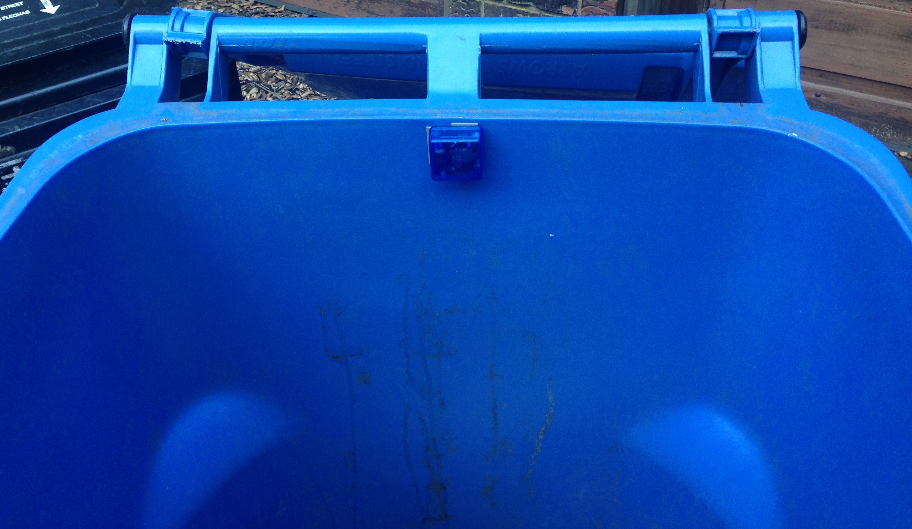
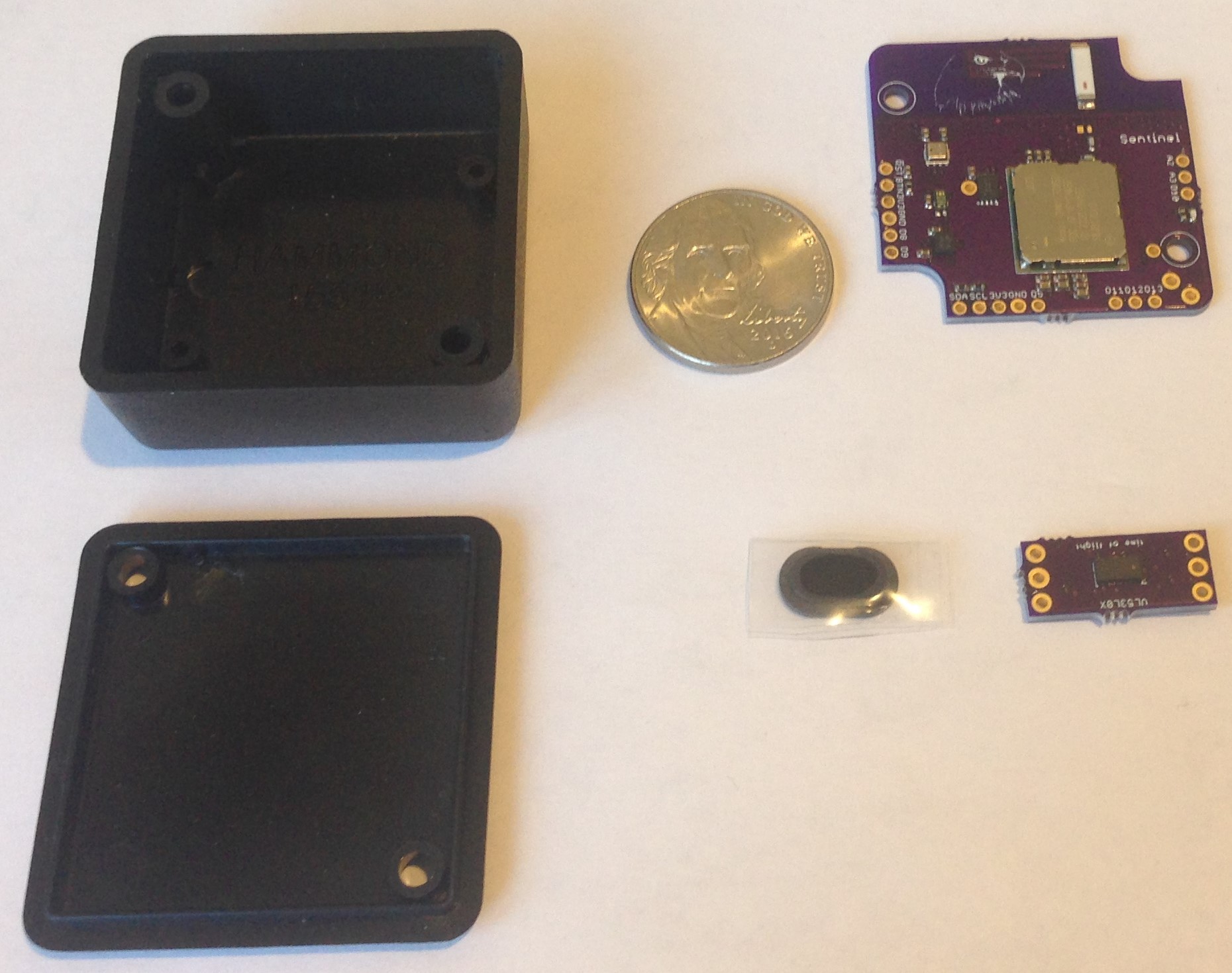
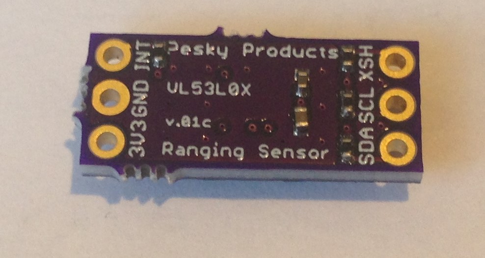
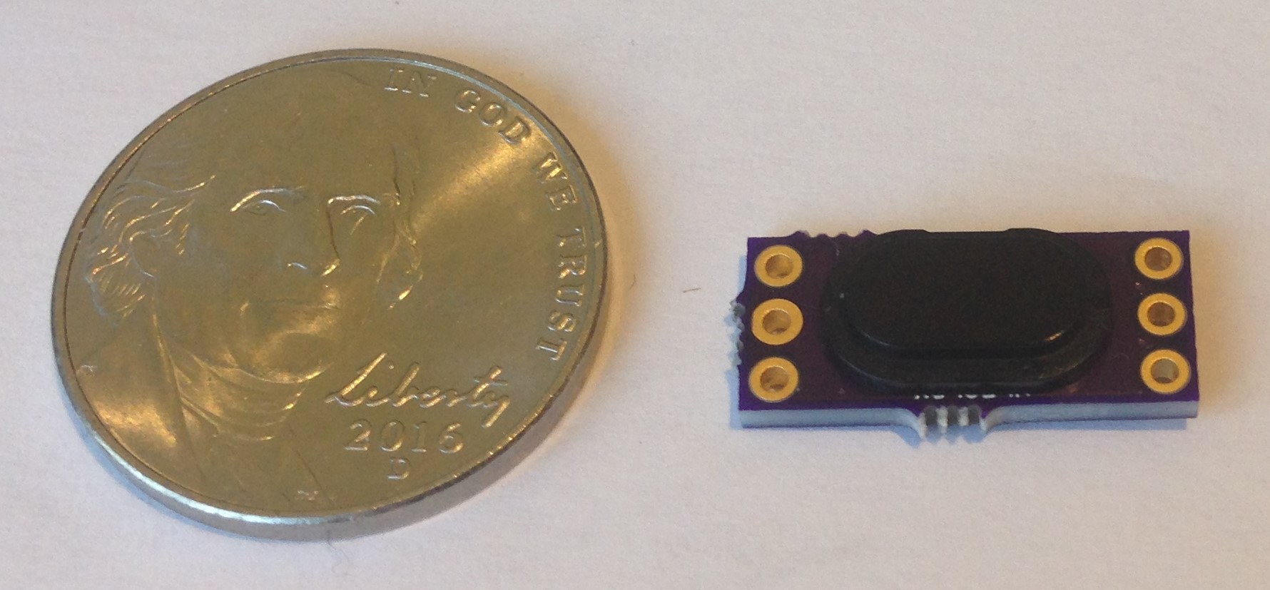
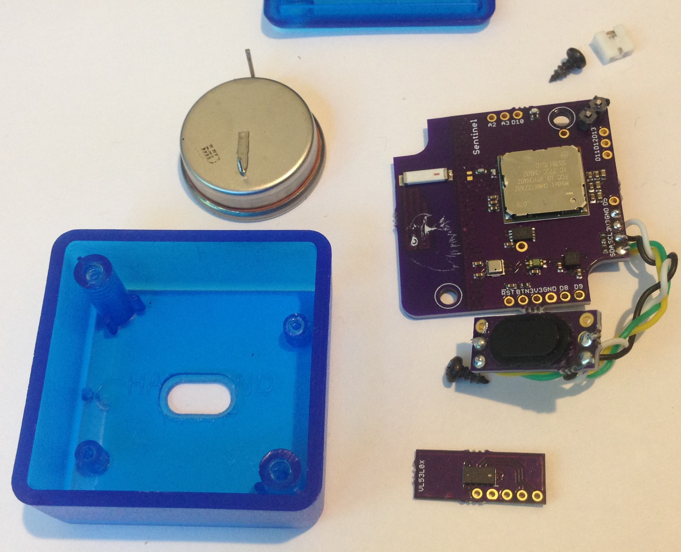 Machining such a complicated shape onto the side of the box proved impossible. But doing so on the box bottom was relatively easy (see above, thank you Greg Tomasch!). I also redesigned the VL53L0 carrier
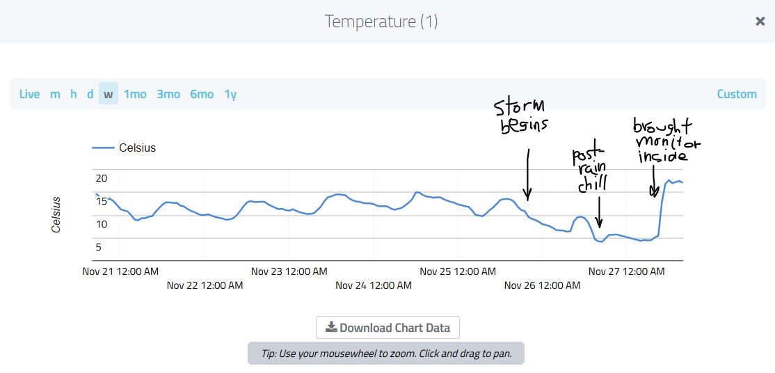
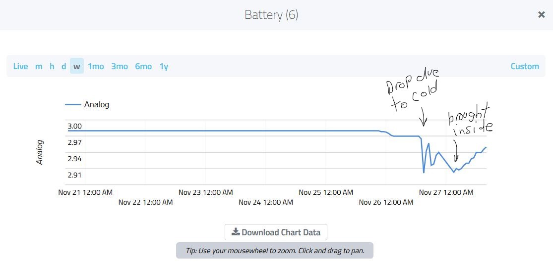
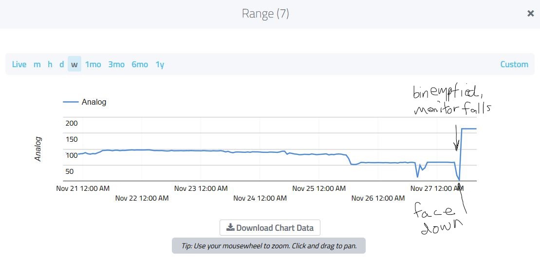
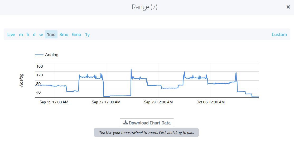
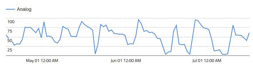
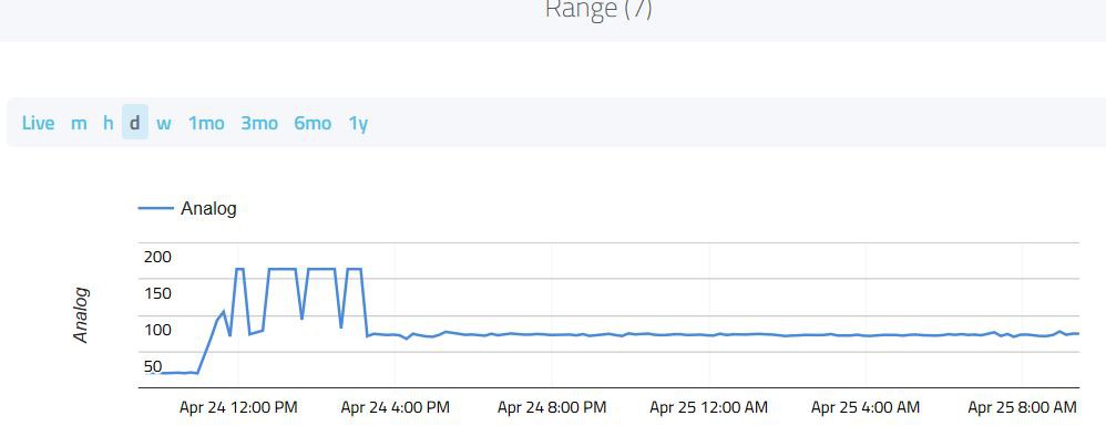
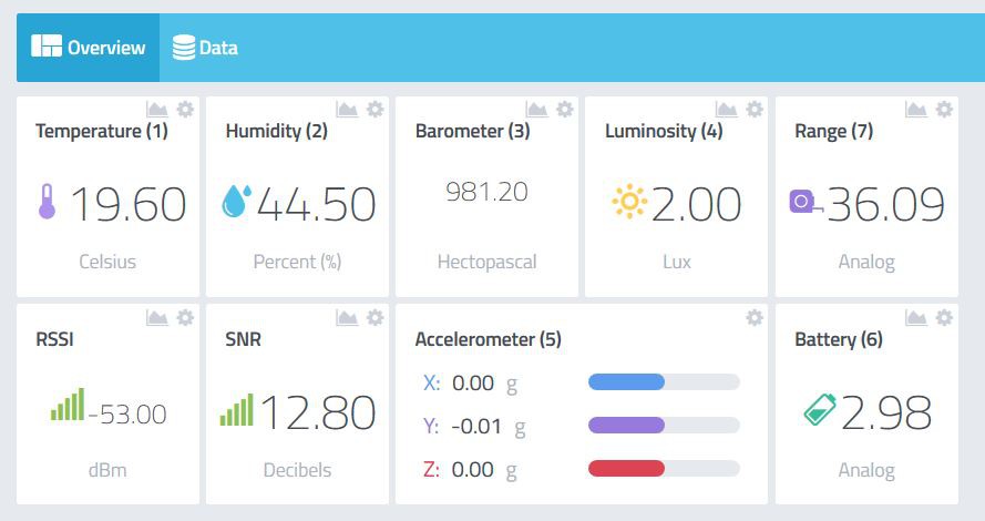
 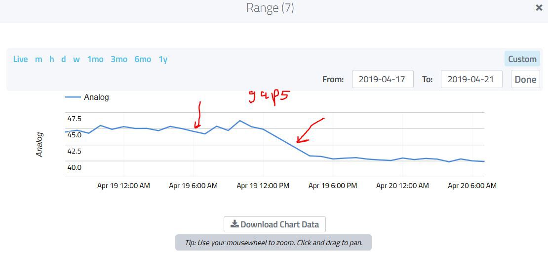 The nice thing about this is that the range is correct; the ranging sensor points straight down and sees whatever happens to be in the middle of the bin. I added some material to the bin a few times over the course of the two days and the bin level dropped from ~60 cm to ~46 cm and then to 42 cm, etc. So the main function appears to work well. I also recorded temperature, pressure, humidity, ambient light level and acceleration (really orientation of the bin lid). So all worked as it should have.
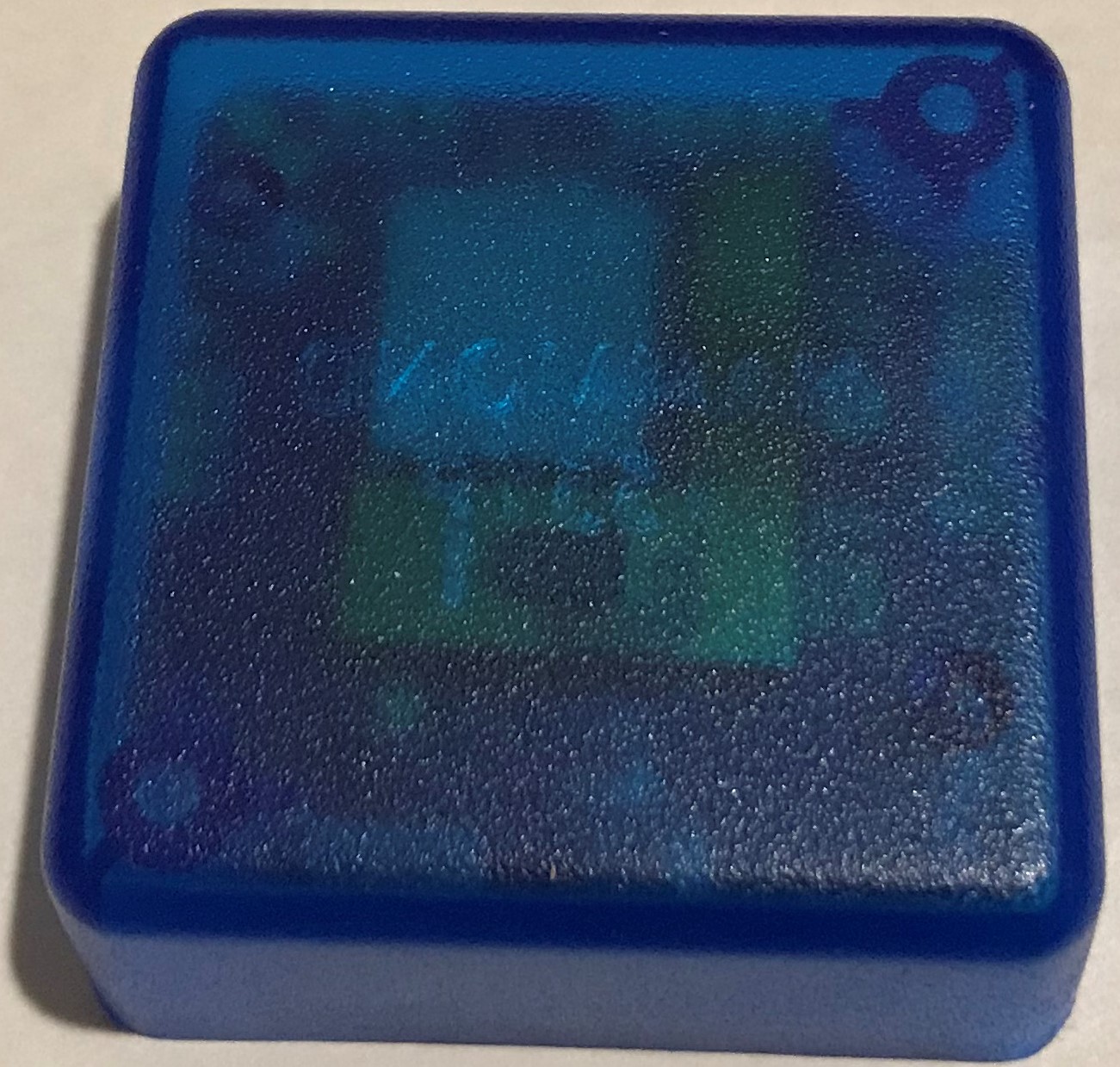
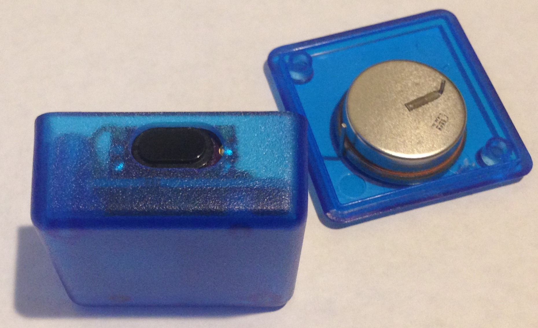
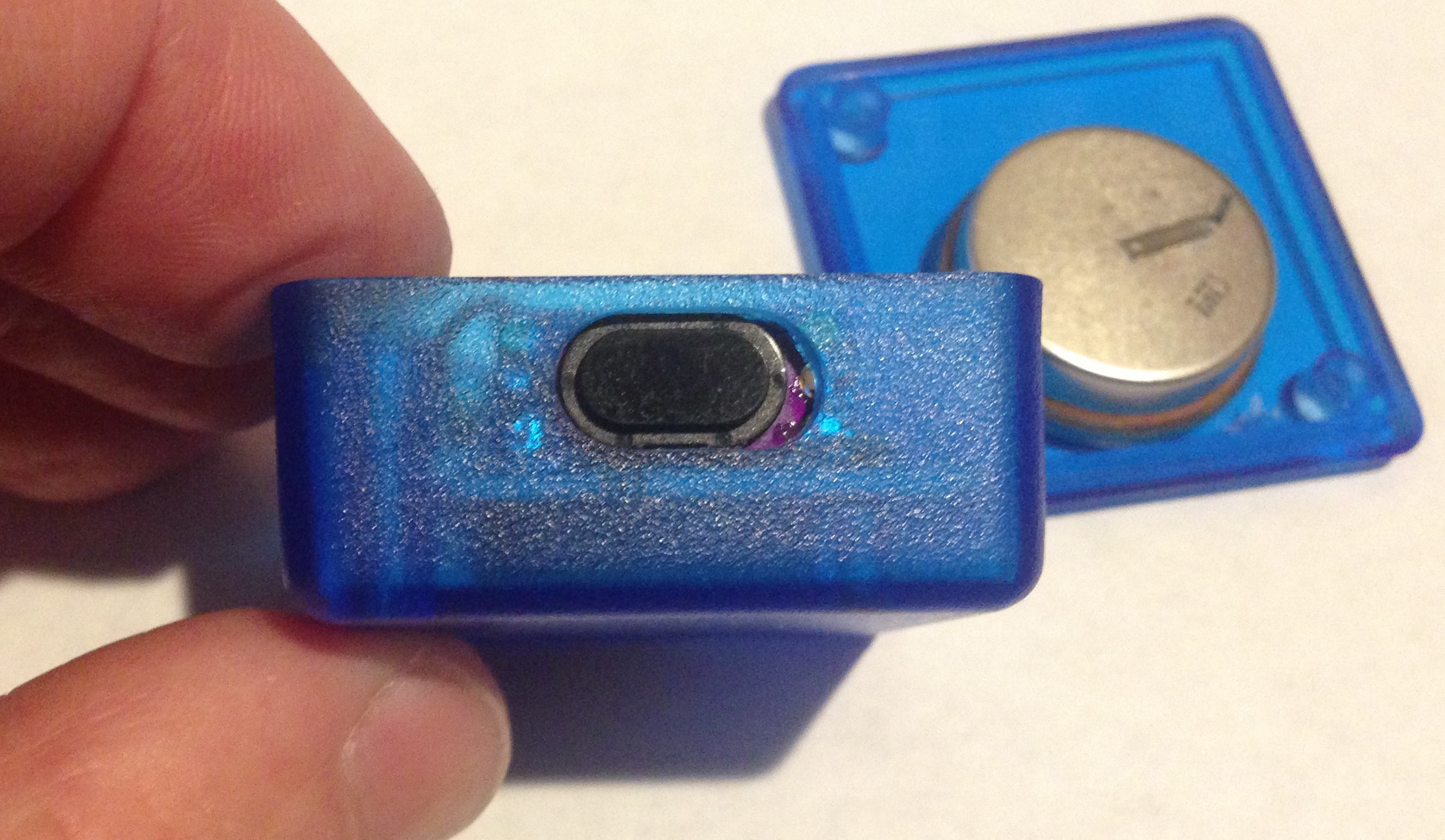
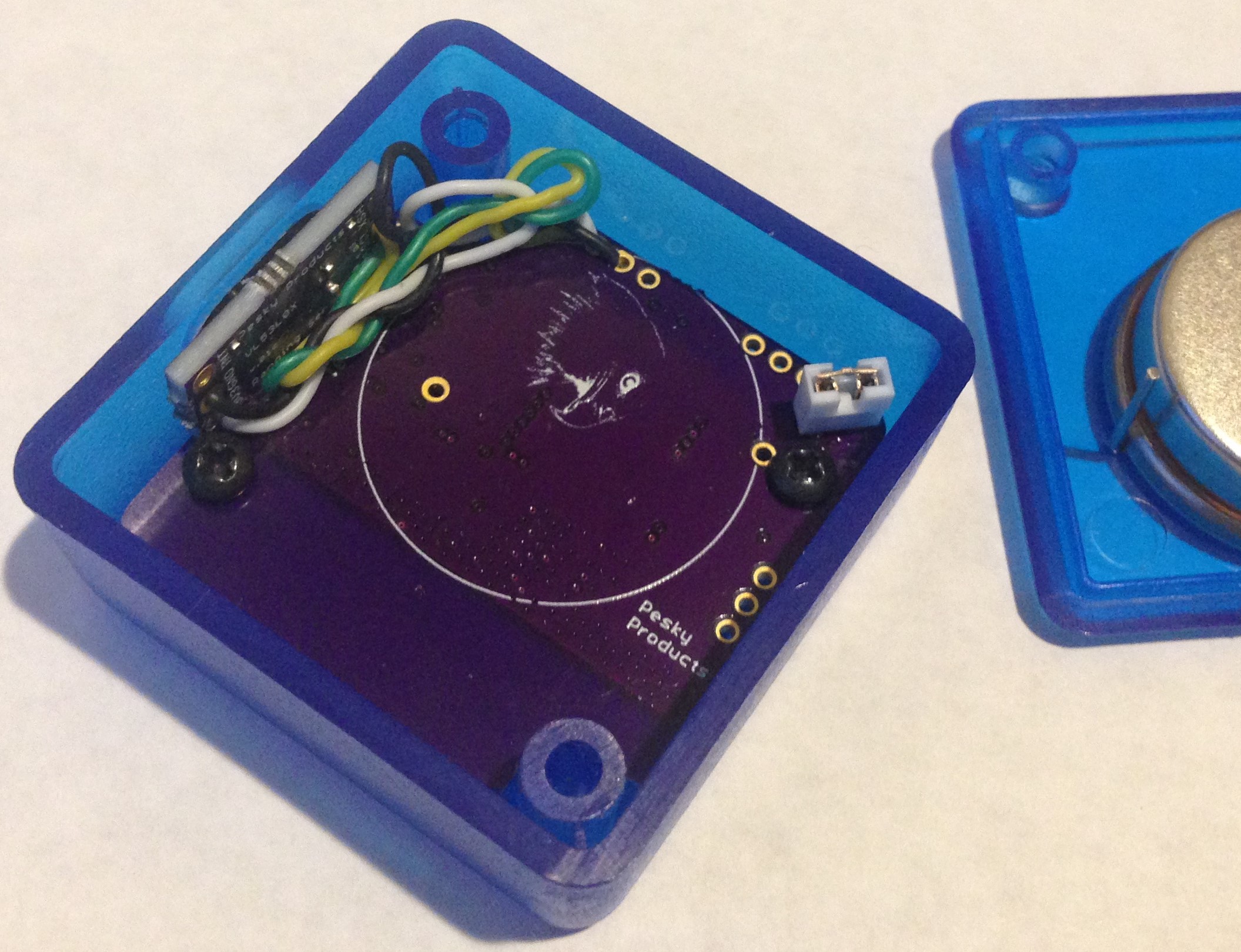
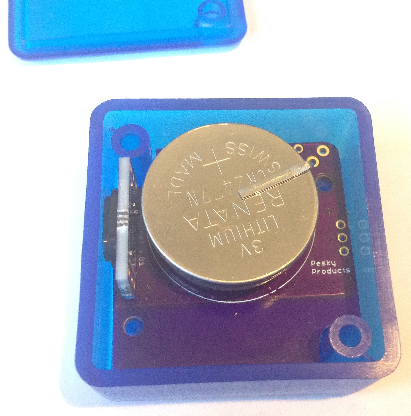
  I am holding the carrier board to the case with double-sided tape, the main board is screwed into the two case mounting holes as before and with the coin cell battery soldered to the main board the package is reasonably rugged and without jitter. A little pre-deployment bench testing to make sure all is working then out to the bin lid it goes. After a few weeks of real-world bin monitoring I will report results...
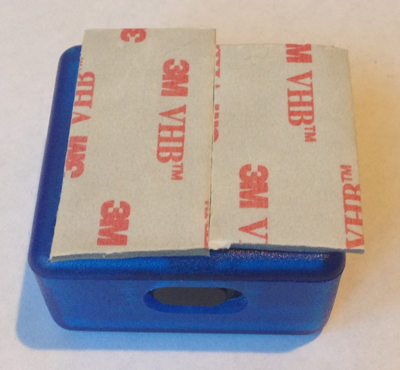


 Ulf Winberg
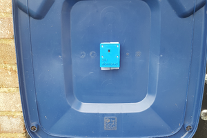
 Stephen Harrison
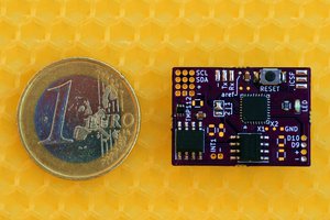
 Jan
Jan