 Marcel van Kervinck
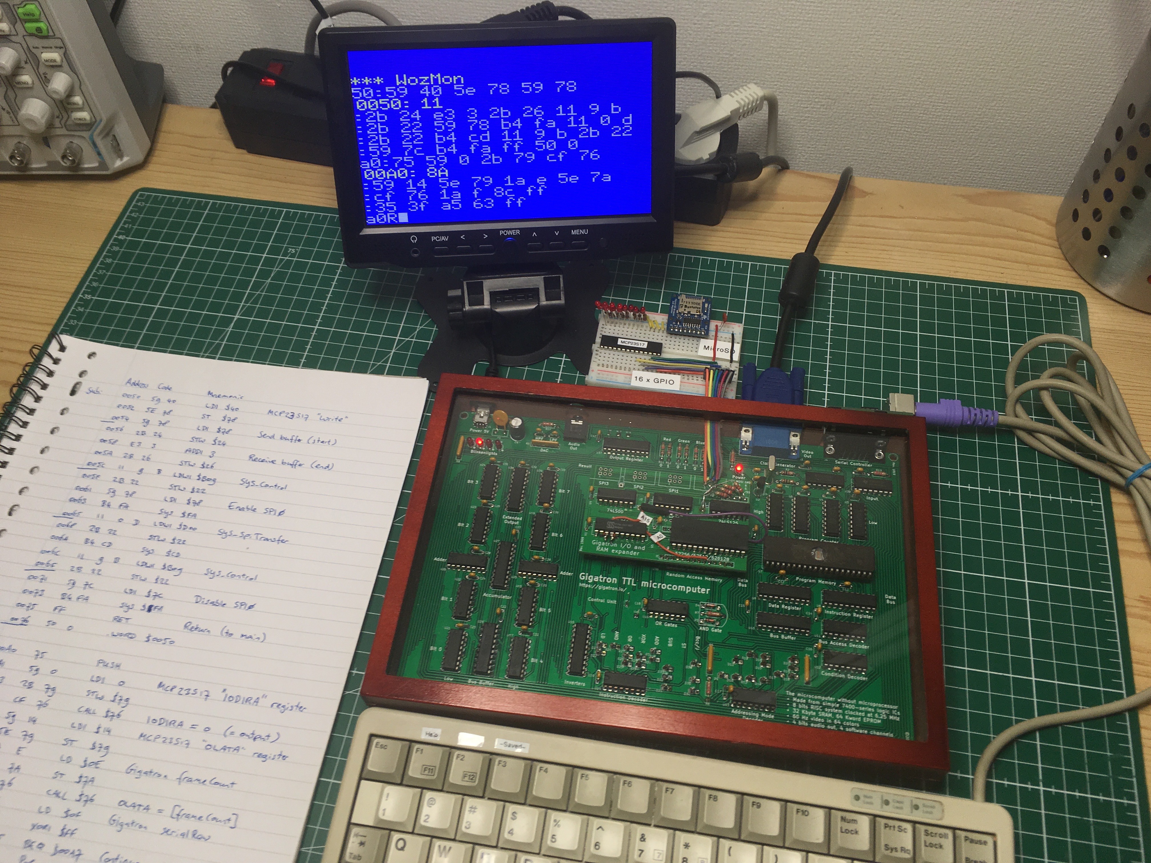
In this video I control some GPIO pins over SPI from a Gigatron TTL computer with the expander prototype. The chip on the breadboard is an MCP23S17 16-bit I/O chip with SPI interface. Because this is the retro challenge RC2019/03, I wrote the test program on paper and toggled it in using the WozMon. Then I started filming:
It works the first time! The test program first configures 8 pins as outputs, and then continuously copies over the Gigatron's 60 Hz frame counter. There are two SPI commands involved:
40 00 00 ; Set PORTA to all-output

40 14 xx ; Send byte value xx to PORTA
It turns out this chip is addressable and can share select lines without causing contention on the MISO line: it keeps its SPI output in high-impedance unless addressed for reading. There are 3 pins for setting its hardware address, giving 8 addresses. We have 4 ports, so we can effortlessly hookup 4x8x16 = 512 GPIO pins...
The next step would be talking to an MicroSD card using the AdaFruit breakout board. (SparkFun has a similar one.) You can see it's already installed on the breadboard. These breakouts come with voltage level shifters, so they should work just like that.
Discussions
Become a Hackaday.io Member
Create an account to leave a comment. Already have an account? Log In.