The selection of the feedback resistors is critical.
The standard output voltage is supposed to be 3.3V. For the appropriate resistor values i just checked the datasheet which had a table with values.
Since the I want to be able to select the output voltage I need to work out the R3 resistor value. When VSEL is high FB2 is connected to GND thus changing the feedback voltage divider and the output voltage.
The equation for R3 can also be found in the datasheet:
Therefor R3 ~ 221kΩ
The final values are:
| Vo1 | Vo2 | R1 | R2 | R3 |
| 3.3V | 5V | 470 kΩ | 150 kΩ | 221 kΩ |
Inductor selection
Since I already know I want to use a 1.5uH inductor, the peak current is a main factor. Again the datasheet helps us with an equation. First we have to calculate the boost duty cycle:
Vout is set to 5V, the max output voltage that will occur. To be sure I set the minimum input voltage to 2.8V.
Now finally we can figure out what current we are working with:
= 10370.67593mA
That is allot of current! Maybe I will not be able to put 2A through this at 2.8V in and 5V out. but a Lipo at 2.8V or 3V will not output 2A anyway. Let's use some more realistic values.
| Vin | Vout | Ipeak | Iout | η |
| 2.8V | 5V | 10370.67593mA | 2A | 0.9 |
| 3.0V | 5V | 6666.925927mA | 2A | 0.9 |
| 3.0V | 5V | 3333.592593mA | 1A | 0.9 |
I feel confident with a inductor that can handle 4A.
Now let's choose a suitable inductor. The site I am sourcing almost all my components from is Lcsc.com.They provide allot of components at low prices. Sadly they don't have the TPS63070 yet so I have get that somewhere else. Back to the inductor: I need a SMD inductor that can handle 4A at 1.5uH and has the lowest possible DC Resistance for a decent price. I chose the FDSD0630-H-1R5N=P3 from Murata with a rated current of 8.5A and 13mOhm DCR for ~ 0.37$.


 Jonathan Bruneau
 Thomas Van den Dries
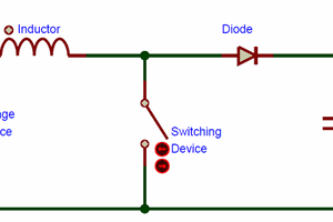
 ElectronicABC
Promising start--are you still working on this? I'm wondering how it worked.