Close
0%
0%

Wendy

Wendy is a UV laser projector for alt photographic process printing

Similar projects worth following
Wendy started with an entry on the cycling74 blog in december '15. A UV laser projector was used for "printing" (insolating, in fact) cyanotype on fabric for an art project.
And a friend calling me, who wanted to create such a thing for images...

Three years later, the project has been let to rest several times (lot of solutions tried and let aside), but we are now able to print pictures, and more.

Wendy uses a 200mW blue / UV laser (405nm), a pair of galvanometer servo, and a raspberry pi with an hifi audio hat for galvo driving.
The software used on both user and laser side is Pure Data, which has powerfull yet easy to use audio tools, as well as mathematics objects, and network, hardware, interfacing tools using external libraries.

Wendy can print images from files on the computer, but it can also create abstraction from wathever idea you can have, like playing with sound, trigonometric tools, and so on..

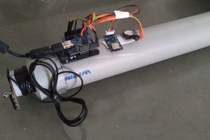
Wendy is composed of the following hardware elements :
- A near UV laser with focusing lens (405nm), and its driver. It could be drived by PWM, but for now it only light-up or shut-down when needed.
- A pair of galvanometer mirrors, and their driver. These are commanded by a tension oscillating around zero.
- An Power supply unit.
- A Raspberry Pi Zero W.
- A pHAT DAC, whose job is to generate the variable tension the galvos need.
- Two buttons to shut down or reboot the Pi cleanly.
- A switch for the laser, for obvious safety reasons !

On software side, Pure Data has been extensively used. The patches has been divided into "elementary tiles", like :
- Open an image.
- Send the image to the laser.
- Display a rectangle (very usefull to place your sheet of paper)
- Set an offset.
- Set angles and distance (so we can manipulate millimeters on the program side).
- And so on.

Pure data has tools for elementary math and sound processing, as well as a lot of user defined libraries (they are called externals). So it can handle images (which great for this project ! ), but also data streaming over a network. The user  simply connect to the laser over wifi with the laser IP, and two connections are used, one over TCP for basic settings (like turning DSP on/off, turning laser on/auto/off, etc.), and one UDP for audio streaming. Pure Data can also connect via serial and read some protocols (midi, OSC), so one can imagine ways to live-control the laser with something else than an image...

  • Episode 6 - Where we talk about how it finally works, now !

    Pierre-Loup M.03/22/2019 at 23:24 0 comments

    After the driving problems with sound cards, the project has been reboot. The solution was quite obvious : use a sound card which can be used as precise DAC, integrate it within the laser projector, and stream data to it.
    A while ago, I started to play with Pure Data, a visual programming software intended to manipulate audio. It has powerful yet easy to use tools, and can process real time audio with ease. It also provides tools for reading file, managing serial connection, and there are lot of external libraries for more specific things. Like data and audio streaming.
    So after having worked on some audio project, I decided to give it a try !
    The user interface has been broken into several modules, each one being a dedicated basic function.
    The first thing needed is to know, given distance and max travel angle of the galvos, what is the max size that can be reach by the projector. The first module therefore computes the ratio there is between a given dimension and the resulting angle the mirror should move to project the laser to this point. At first this module was doing elementary trigonometric calculus, using tangent to compute the right position, and exporting each angle in tables. Viewing the table the line was quite straight, so I wonder if tangent could be replaced by a coefficient that would enable fastest realtime computation. A spreadsheet with graphics shows that for angles bellow 10°, a line can be used to approximate tangent, with an error that stays under 0.4%. So no more trigonometry, an angle per mm ratio is sufficient ! This module is given the max travel angle, distance from projector to wall, and then output angle per distance ratio for both axis, as well as max distance, max angle, and other parameters used by other modules. It is also used to set DPI, even if this is not directly linked to the projector, and more to pictures.
    The second important module is the send module. It connects to the laser using TCP protocol to send control data, like turning DSP (digital signal processing) or laser diode, on or off. And it also sends the position data (managed as audio) using UDP protocol.
    On laser side, Pure Data is used as well, it runs on a headless Rapsberry Pi Zero that lauches the program as soon as it boots. Pure Data can turn the laser on or off using a library which interface WiringPi digital pin.

    Then the files... GEM is a librarie used to process real time image. It can be used to generate particles, manipulate 3D objects, and for the laser it's only used to open an image and read its pixel values. It has something great : pixel values that are read from the picture are resampled, so any file can be output with any resolution or size, without tiling or pixelised effect. That's great because it would be something demanding time and coding otherwise.
    The image opened with GEM is parsed according to desired DPI (default DPI is computed on file opening), desired projection size, a scanning angle ranging from -90 to 90°, and a parameter which enables to skip lines during parsing. It can also apply a threshold on the picture to set any pixel to black or white, given its value. For each output pixel, both X and Y coordinate are output, and the corresponding pixel value is output too.

    There is another module which job is to generate audio stream to project the picture. The idea while spliting image parsing and data computing is that one image can be interpreted several way. One is to simply project shades like the original picture, but it could also use sinusoid lines which amplitude varies after shades of the original file. Data computing could also be made on the projector.
    When this module receives data from the image, for each X,Y couple it computes the vector length from the current position to the new one. It then attributes it a travel time, which is computed using length, pixel value, and a parameter that gives a correct exposure value for black. Each value is then store to a table.
    When the image is...

    Read more »

  • Episode 5 - Where we talk about programming environment

    Pierre-Loup M.03/13/2019 at 08:37 0 comments

    One crucial point about the projector is that it can be used by anyone (anyone being, namely, the friend who put money in the project). Used by anyone means having a graphic user interface. That was one of the reason I first choose Python for the user side code : Python has several tools and environment at hand.

    But Python was let aside because of computation speed, and C choosen instead. And choosing a developpment environment for C with GUI was not an easy task.

    At least till I cross the path of Qt. Qt has an embedded powerful GUI tool which can be use to graphically design windows and containing every kind of display object you could need. And it also has libraries available for almost everything you could need in your project, from basic file parsing to image or vector manipulation, audio playing and streaming, serial or network connection, etc. And it is extremely well documented !
    So, Qt. One problem though was cross compilation, which is possible, but I didn't succeed in cross-compiling for window (why don't everybody use Linux, I still wonder ! :D )

    But, there was this problem with audio hardware not being the same on every computer, so, switch again to another solution... Anyway, I'll probably use Qt again if I need to run a program with a powerful GUI. It really make thinks easy when developing complex applications.

  • Episode 4 - Where we talk about alternative to Arduino and DAC

    Pierre-Loup M.03/12/2019 at 09:19 0 comments

    Lasers galvo are variable-tension driven. If you want to set the galvo to its middle position, you give it 0V. If you want, say, -10°, you give it -5V. If you want 5°, you give it 2.5V. (arbitrary values here). There is a hardware peripheral on every computer that goes the same way : sound ! Is was tempting to give it a try, and simply connect the control line of galvo drivers to the 3.5mm output jack of a computer ! And every computer can (should, in fact...) use at least CD quality, i.e. 16bits, 44100Hz ! That would be nice...

    The main program was then modified, and all that was linked to serial communication were cancelled. PWM for driving laser intensity were cancelled as well, because it should have been synchronized with audio stream, which would have been a difficult task. Instead pixel value was map to a speed (going slow let the time for the laser to expose the image, going fast doesn't expose at all), and pixel positions were transform into a value oscillating from -1 to 1 on both X and Y axis. -1 and 1 correspond to extreme angles on the galvo. The values are then written to an audio file, using pixel value / speed to generate a ramp from one pixel to the next.

    And it worked out of the box ! Very reliably, and repeatably ! Each pixel was precisely positionned, enough to send the image several time without seeing any gap ! Then we tested it on a netbook it should run on (this project was started with a friend interested enough in it to put some money on the table), and... Total fail. It appeared my Thinkpad has a "real" DAC, but my friend's netbook has what looks like a PWM soundcard... Totaly unreliable. Big gaps between pixels, and sending the same data lead to different output position.. Surprisingly enough, testing it on my iMac, which has more than decent audio quality, lead to strange behavior: X axis (fast scanning) was precise enough, but Y axis was always centered. This is due to the low scanning speed on that axis, and the sound card zeroing out what appears to be silence...

    The audio solution was usable, but it had to behave the same every time, regardless of the computer used as user interface...

    At this point, I had been working on the project for months, and I couldn't write one more line of code... So the laser was put on a shelf, and it lied here alsmot two years !

  • Episode 3 - where we talk about Arduino boards, fixpoint math, and I2C.

    Pierre-Loup M.03/06/2019 at 16:25 0 comments

    After having changed the serial protocol for a much faster iteration, other problems arose, as I said.
    It quickly appeared, once the serial was fast enough for pictures to be reliably sent, that other parts where not. The Arduino Uno, for instance. It quickly became obvious that it lacks the speed to compute trajectories from coordinates received (here we can mention Bresenham interpolation, which was implemented ont the Uno). A first step to speed-up computations has been to use fixpoint math, which was a big plus. But this was not enough.

    So the Arduino Uno option was cancelled, and an Arduino Due used instead. The Arduino Due was fast enough, but... It then appears than the I2C speed was another problem, and the DAC was controlled by I2C. It simply can't go fast enough to stand the speed needed for laser scanning. It also appears that the DAC used was not reliable enough. Same input values could lead to slightly different output values. And it's a real problem when a one-bit difference is visible on the final picture...

    So the DAC was put aside. And Arduino where put aside too, because... Serial speed, once more. It was still quite slow, event with the native USB capability of the Due. I've learn later than USB communication is reliable using big packets of data, and that sending five bytes at once is a waste, the protocol beeing quite eavy regarding the message size... I'll know it, now.

    So it was once again time for new solutions to be searched for.

  • Episode 2 - where we talk about Serial communication

    Pierre-Loup M.03/06/2019 at 16:06 0 comments

    The first idea was to use an Arduino to drive the laser. First problem was that serial from computer was faaaar too slow. Imagine sending for each pixel a string like "x17235y25994z210" (x-position, y-position, plus laser intensity), with each char being one byte. Now imagine you use an image that is 1500x2000px ! At 115200 baud, it takes more than an hour. Not only is it very long (imagine waiting an hour when you print a document at office !), but it gave burnt prints, as the images were too much insolated ! And there were the need for other data to be sent as well.

    Other solution had to be found. A protocol was designed for the serial communication, with a byte containing flags for the data to be received in each packet, and one or two byte for each value to be sent, so the Arduino knows exactly what to do with bytes received. Only the changing bytes were sent on each packet, which made the communication much faster. A control sum was also added to verify that each packet was correctly received. This took some time to develop, because some bugs were hidden here and there... I've learnt that MSB and LSB can be tricky to domesticate when using two systems that doesn't handle it the same way ! And that bit shifting can be quite hazardous. :)

    This serial protocol was of course way faster and reliable (at least 1440 coordinates per second), but then other problems arose...

  • Episode 1 - where we talk about programming langages

    Pierre-Loup M.03/02/2019 at 21:06 0 comments

    This project began using Arduino on laser side (more on that later), and Python on computer side. Maybe a bit ambitious for a first project using Python, but I need goals to learn something new. :)

    I don't remember exactly what specific libraries were used for the user-side program, but I remember two things. The first is that it quickly became quite intricate, with sub-programs for different functions that were inter-related, and all linked to the GUI. This is mainly a problem of program architecture, but to me Python made the things a bit more difficult...
    The second thing is that if Python is very good at doing a lot of things, when it comes to compute big batches of data (i.e. compute an angle for each X and Y position of each pixel of an image) it's quite slow... First tries were made with small files, but 2 minutes for a 300x400 pixel image is not something we want to experience each time we want to create picture !

    So Python was quickly cancelled for this project.

  • Episode 0 - Where we take some elements, cook them together, and try to create something.

    Pierre-Loup M.03/02/2019 at 20:41 0 comments

    This projector has been created from the very beginning to print images from files, using cyanotype or other historic photographic processes (one can name dichromate gum, bromoil, salt paper, Van Dike, wet plate collodion, and so on).

    The main elements constituting this projector are :
    - A laser. Near UV, as the vast majority of historic photographic processes are mainly UV sensitive. 405nm are widely available, and do the job very well.
    - A pair of galvanometer mirror. With them the laser beam can be moved wherever we want to, fast and repetitively.
    - Something that can receive command and coordinates, and transform it to something that the galvo can use, namely a variable tension. For that purpose an Arduino were first chosen, with a 24 bits DAC module.
    - Something that can use an image file and transform each of its pixel into a coordinate (X and Y) and intensity value. And play with trigonometry too, as the galvanometers move around an axis. That kind of thing is called a program. And it has to have a graphic user interface, as this laser is intended to be used by people who can lack the abstraction ability needed to use a command line...

    More to come !

View all 7 project logs

Enjoy this project?

Share

Discussions

Similar Projects

Does this project spark your interest?

Become a member to follow this project and never miss any updates