 Alastair Hewitt
Things inevitably slow down during the summer. Not much happened in July and it will probably stay that way until well in to September. The project is still active though and the plan is to get a working PCB built by year end.
The last two logs detailed some significant design changes. The GPU change is based on the assumption that both the horizontal scan and serial communication timing can be combined. The only frequency where this is possible is 38.4 kHz. Unfortunately, there are no defined video modes that use this frequency. The hope is that monitors will support some form of generalized timing.
You would think a simple Google search would yield some answers to this question, but alas no. There is a standards body that was formed to define this stuff, the Video Electronics Standards Association (VESA). They created four standards of interest:
- Display Monitor Timing (DMT)
- Generalized Timing Formula (GTF)
- Coordinated Video Timings (CVT)
- EDID Timing - defined by the Extended Display Identification Data (EDID)
The first document detailed a set of standard video modes. But this was during the era of multisync and multscan montors that could support an arbitrary range of video timings. So how arbitrary? VESA came up with the GTF to define these generalized timings. But they were too general and no one could support them. Then came CVT to put some constraints on things as well as introduce reduced blanking. Both GTF and CVT define generalized video timing that would support a video mode of interest.
So do monitors support these generalized standards? Apparently not. The final standard (EDID) provides a way for the monitor to tell the graphics card that is does not support generalized timing and list the few standard timings it does. This appears to be how everything works these days and only defined standard video modes are available unless you can dig up a 20-year old multisync CRT monitor.
So how standard does standard have to be? There are a couple of standard video modes that come close:
- 640 x 480 - 75 Hz vertical, 37.5 kHz horizontal, 31.5 MHz pixel frequency
- 800 x 600 - 60 Hz vertical, 37.9 kHz horizontal, 40 MHz pixel frequency
The ability to generate a usable video signal is a gating factor for the continuation of the new design, so this needs to be tested. This was a blocker so it was time to do some experimentation. This was done by modifying Nick Gammon's Arduino sketch to generate a VGA signal. The timer settings were changed to generate the 38.4 kHz horizontal frequency and both the 60 or 75 Hz modes were tested.
The results were slightly mixed, but promising. Two older LCD TVs had very little tolerance for non-standard timings and would not sync. Newer LCD monitors and TVs had no trouble handling the higher frequency as can be seen below.
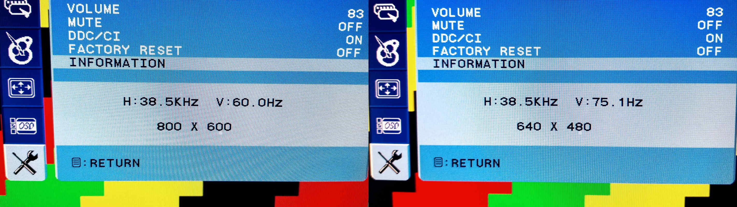
[Note: the timing is slightly fast and the numbers are rounded up in the above images]
The acid test was to see if a cheap VGA to HDMI converter could handle this timing. This is important since VGA support is in terminal decline. Almost no monitors and TVs now ship with a VGA input, so a VGA to HDMI converter may be required as part of the standard configuration.
[Update] After additional testing it appears the cheaper VGA to HDMI converters are just simple analog-to-digital converters with a buffer and data serializer. This means what ever frequency you give them is just passed through from the VGA input to the HDMI output. The hope was a device like this would convert the non-standard timing and support the more sensitive monitors. Additional testing confirmed that if the monitor does not support the non-standard timing via the VGA input then is will not accept the timing via the HDMI converter.
A panacea to this timing issue may still be available in the form of a VGA to HDMI converter/scaler. This is a more expensive device, but will actually consume the VGA input signal and then generate a 720p or 1080p HDMI signal. This will provide a stable and usable signal assuming the scaler accepts the non-standard VGA input timing. This also solves another potential issue: The latest UHD TVs no longer support 480p and won't accept 640x480 even with the correct timing!
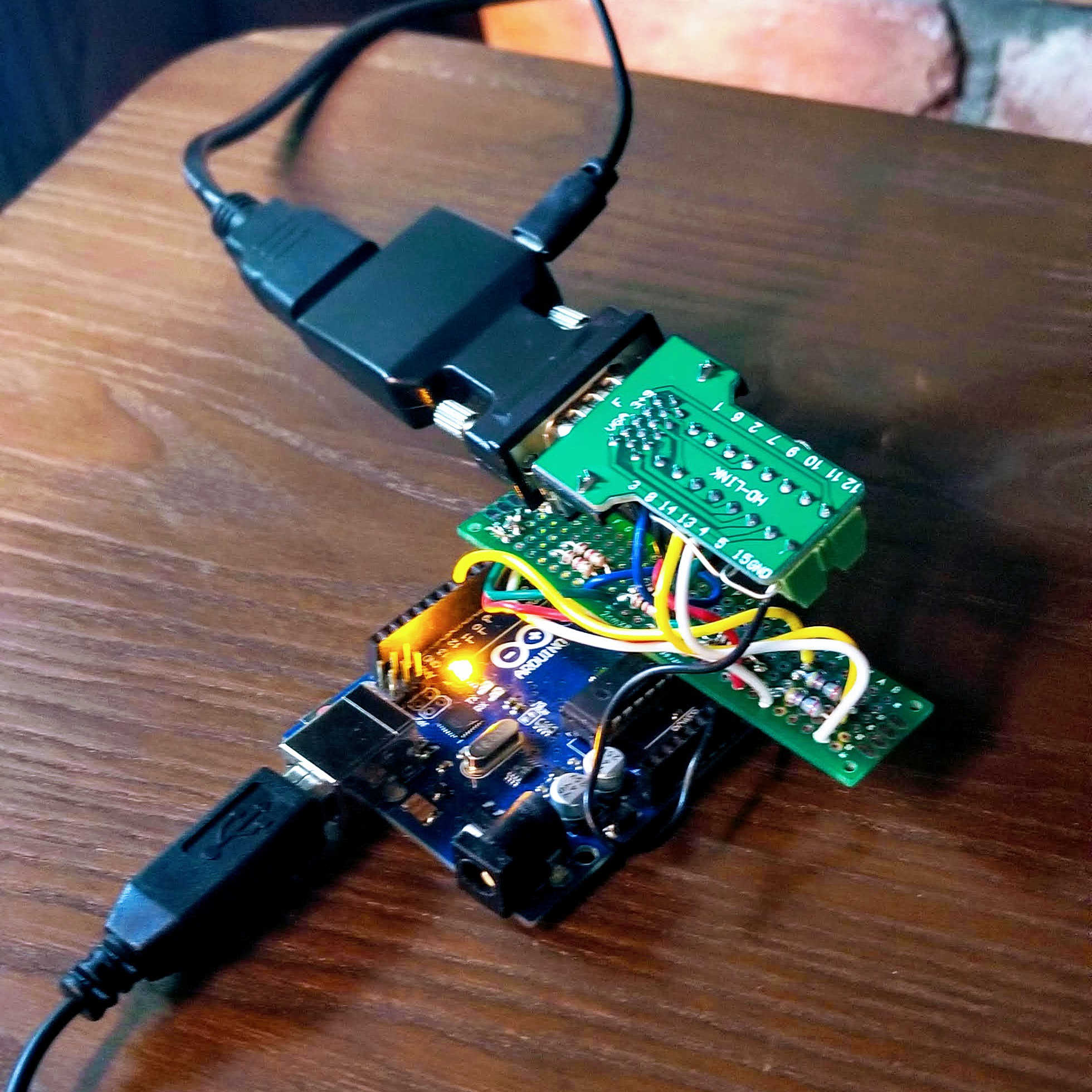
The picture below shows the Arduino, VGA breakout, and a cheap $7 VGA to HDMI converter.
So to wrap up, here are the details of the planned video modes: The pixel/dot clock will be 31.95 MHz (although 32 MHz is close enough). This is divided by 4 to generate the process clock to drive the horizontal counter. The counter starts at 32 and counts to 240, for a total of 208 process cycles or a frequency of 38401.44 Hz.
The text mode and hi-res graphics mode will use a vertical frequency of 75 Hz. This requires a total of 512 lines to divide the 38.4 kHz down to 75 Hz. The true standard uses 500 lines to divide down a 37.5 kHz horizontal frequency. This means sending an additional 12 lines per field.
The lo-res graphics mode will use a vertical frequency of 60 Hz. This requires a total of 640 lines to divide the 38.4 kHz down to 60 Hz. The true standard uses 628 lines to divide down a 37.879 kHz horizontal frequency, again an additional 12 lines will be sent. The low-res pixels are sent at a rate of 8 MHz while the monitor samples with a 40 MHz dot clock. This means each pixel is stretched to 5 on the SVGA display, so each line will be repeated 5 times to match.
Discussions
Become a Hackaday.io Member
Create an account to leave a comment. Already have an account? Log In.
thanks for the write-up! i am doing some video experiments as well, and this information was very helpful!
Are you sure? yes | no