 Alastair Hewitt
The Rev.1 boards came in earlier this week and a couple where built and tested. The only firmware that exists generates a text mode video pattern, so some unrelated components were not fitted.
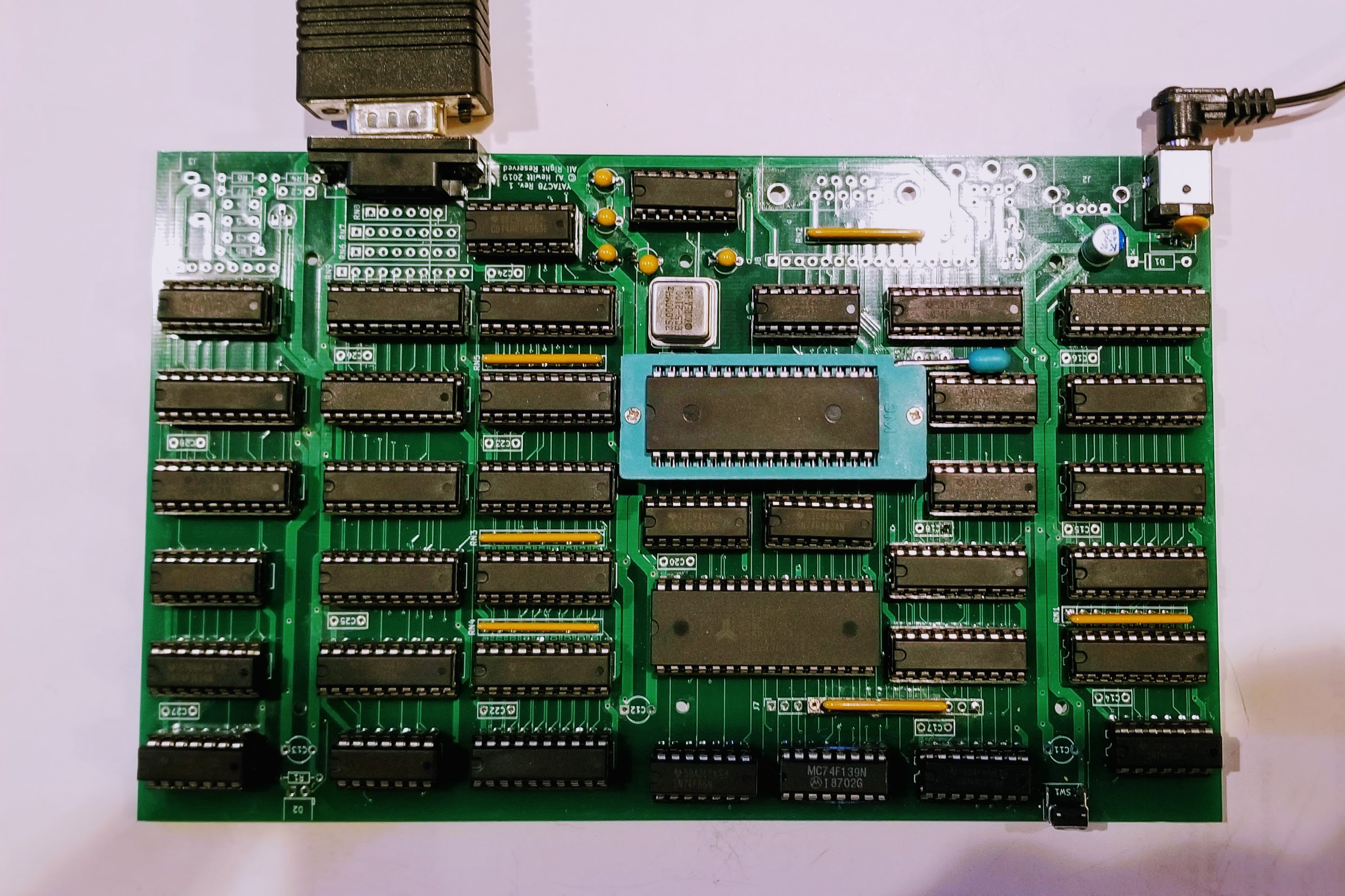
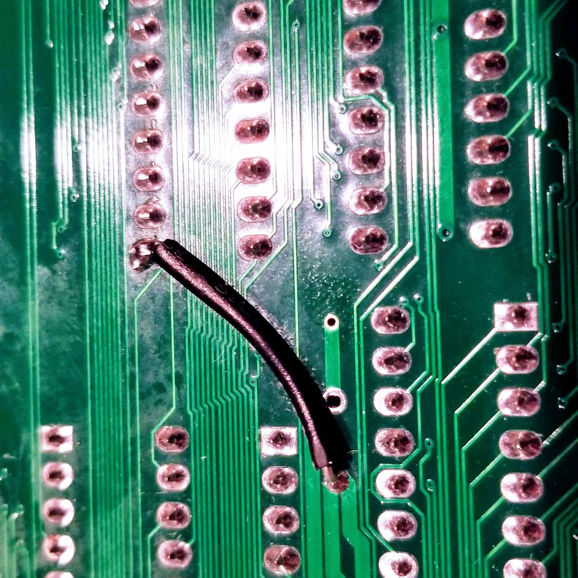
It took a few hours to resolve a couple of issues with the PAL. The pins were reassigned on the PCB version, but the old JEDEC file had been programmed. The reset input shouldn't need an external pull-up resistor, but the PCB version appears to need one. This was patched on the back of the board.
The test program worked first time once the PAL issues were resolved. "Worked" as in it generated a somewhat glitchy test pattern and only with a 25MHz dot clock. This was not encouraging, since this is a similar performance level to the breadboard. Several hundred pads were soldered on the board and this resulted in a lot of flux. This was cleaned off as a precaution, but didn't seem to change anything.
Some initial probing started to identify the source of the problems. The power lines to the chips were showing a decent amount of noise. The board being probed did have decoupling capacitors, but these seemed to be less effective than just using a low inductance path to ground instead. Almost all the glitching was eliminated by adding a single ground return from the RAM chip to the lower power bus.
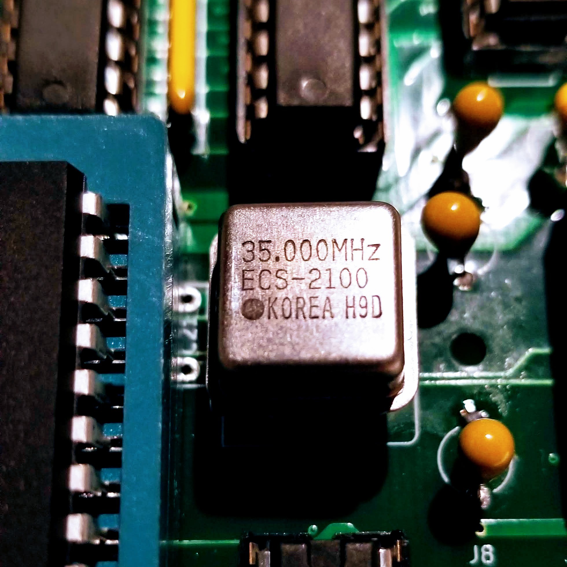
After that the clock speed was retested and the board was now able to reach its maximum dot clock speed of over 36MHz. The closest available oscillator is 35MHz and this was tested to good effect. This results in a machine clock of 17.5MHz and a memory access cycle of 57ns. Both the NOR flash and OTP ROMs respond in about 50ns, so there's 7ns left in the memory access cycle. A 40MHz oscillator was also tested, but there's no time left in the cycle to meet the setup times and latch valid data. The board may go a little faster (36.864?) but the current 7ns buffer is a good place to stop.
Things were close, but not quite there. One final discovery appears to have cleared up the remaining glitches though. The dual 2-4 decoders are obsolete in the 74F series, but I was able to pick some up on Ebay and I've been using these. I want all the parts to be in production and the design should work with the currently available 74ALS139. This chip is routinely tested to make sure the board will still work and it appears that changing to this version solves all of the remaining glitches. Like many NOS chips listed on Ebay, the 74F139 chips I bought may have come from a rejected batch. It's also possible these 1987 chips have deteriorated over the past third of a century... Either way it looks like the board is now 100% working!
Things are now blocked on further hardware testing until more firmware is written. The two bitmap graphics modes need testing (building out the 8-bit video DAC), the audio system and amplifier/filters, and the serial - both keyboard and RS232. All these require new code and that code will require build tools. Once the rest of the hardware testing is complete a Rev.2 board can be built to rework the grounding issues.
Discussions
Become a Hackaday.io Member
Create an account to leave a comment. Already have an account? Log In.
Hurray!
Are you sure? yes | no
awesome work and write-up!
Are you sure? yes | no