 Alastair Hewitt
Not much has been said about the audio yet, but it's definitely a feature and currently being tested.
First a quick overview of the zero page to better understand how the audio system works. A zero page is typically the first page of the memory and only requires a single byte to address one of 256 possible values. In this design the zero page is put in the upper bank of memory along with the display. The display uses all the pages of this memory, but only the first 209 bytes of each. To accommodate this the zero page is oriented to be the last byte of each page. So rather than setting the Y index to 0 and using the X index to address the zero page location, this design sets the X index to 0xFF and uses the Y index to address the location.
The 0xFF value for the X register is created by adding pull-up resistors to the address bus and leaving the X register in tri-state during the zero page access. A similar approach is used with the GPU where both the H and V registers are left in tri-state during the horizontal blanking period. This selects not only the zero page, but the very last byte at the top memory address of 0x1FFFF. This last byte of the zero page is used to store an 8-bit audio sample.
So during the horizontal blanking period the GPU reads the audio sample and puts it on the lower 8-bits of the ROM address bus. Normally the GPU context selects the font area of the ROM, but in the horizontal blanking period the ALU context is used. Not only that, the upper ROM address is also left in tri-state and pull-up resistors select 0xFF of the ALU. This selects the unary identity function and passes the value of the audio sample through the ROM unaffected to the glyph register.
The glyph register does double duty: It acts as a pipeline for the glyph line while colors are loaded, but during the blanking period it holds the audio sample read from the zero page. An audio DAC is added in the form of an R2R resistor network to output the analog version of the audio sample during the blanking period. The audio DAC output is only sampled during the blanking period to reject the video signal during the non-blanking period. The sampled signal is then filtered to remove the high-frequency and DC components.
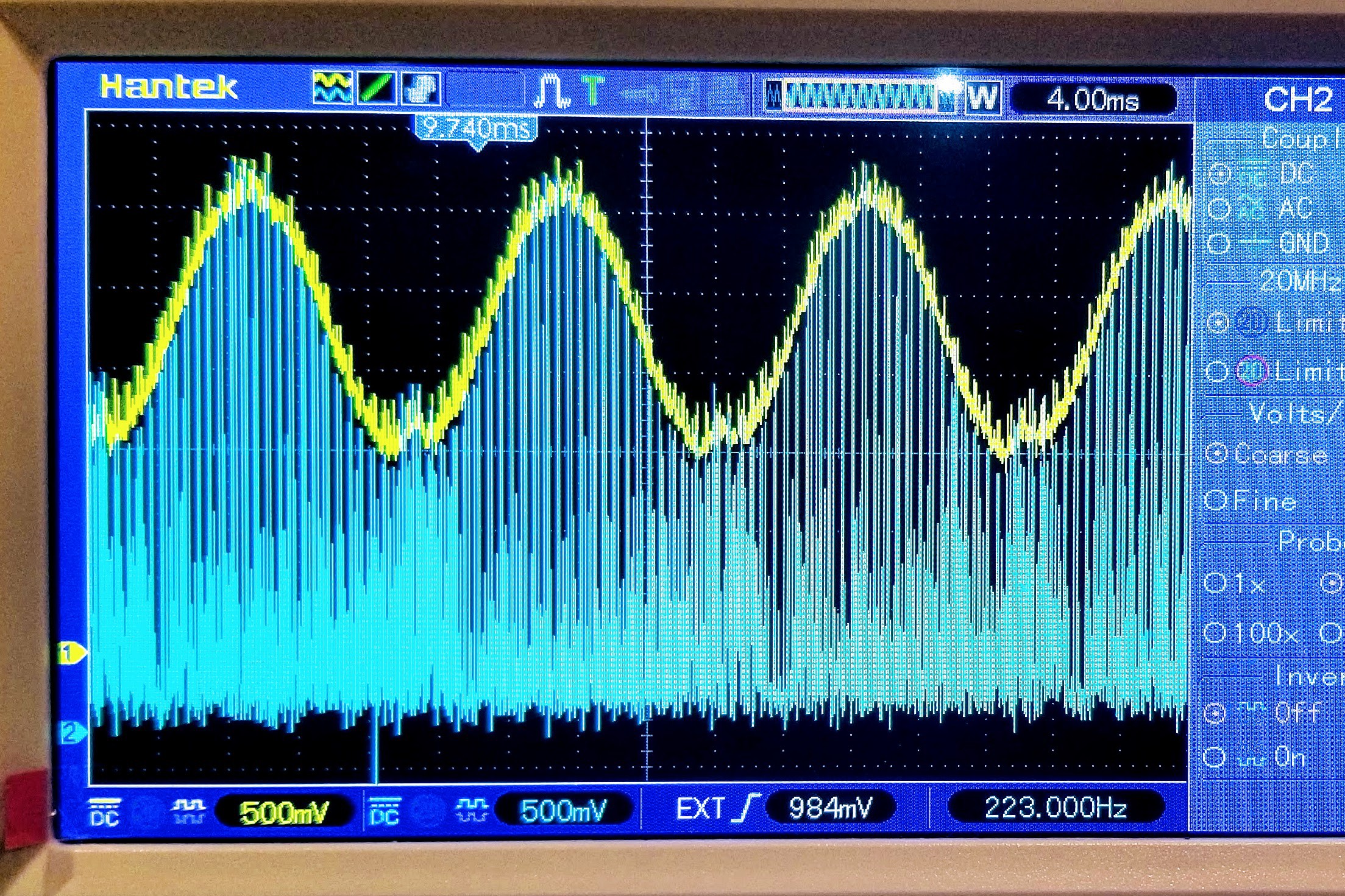
To test the audio a sine wave was added to the ROM and addressed by the video vertical line address. This results in a sine-wave at the video field rate of 60 Hz and sounds exactly like electrical hum :) One issue identified is with the sample and hold circuit. This currently uses a BS170 MOSFET with a threshold voltage of only 0.8v and this is not completely turning off on the bottom half of the cycle. The image below shows the sine wave transposed up but still experiencing some breakthrough of the video signal during the bottom part of the cycle. Switching to a BS270 may fix this, but further investigation is ongoing.

Discussions
Become a Hackaday.io Member
Create an account to leave a comment. Already have an account? Log In.