 Alastair Hewitt
The Rev. 2 PCB came in yesterday and the first sample has been built and tested. The image below shows the Rev. 1 (left) and Rev. 2 (right) boards. The plan is to keep one fo the previous revisions of the board on hand to compare in the case the new revision is a step backwards... which unfortunately appears to be the case here...
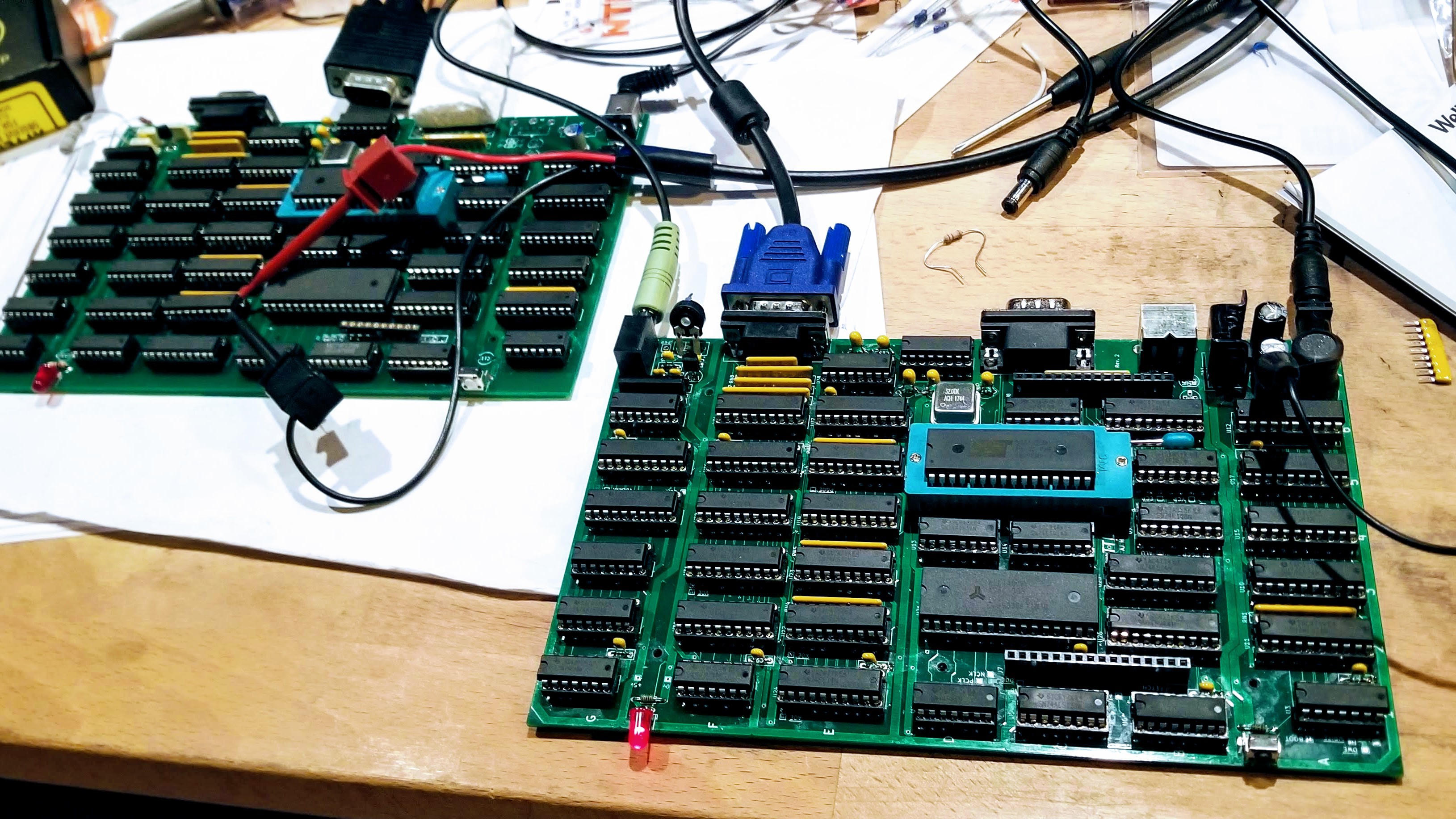
The biggest delta between the two revisions was a new power distribution layout including a cooper pour on the back for a ground plane. The Rev. 1 board needed a few patch wires to add additional ground return paths. These problems should be eliminated on the new board and so far the power lines do look a lot cleaner.

The new board booted up first time and flashed the blinkenlight on and off at the correct 1Hz frequency. The V-sync signal was glitchy and prevented the video from syncing. Dropping the dot clock to 32MHz fixed the issue and the board appears to be completely stable at this speed. This was with the slower NOR flash ROM though, so the faster OTP ROM was tested. This didn't work at all... at any frequency, so something is definitely not right.
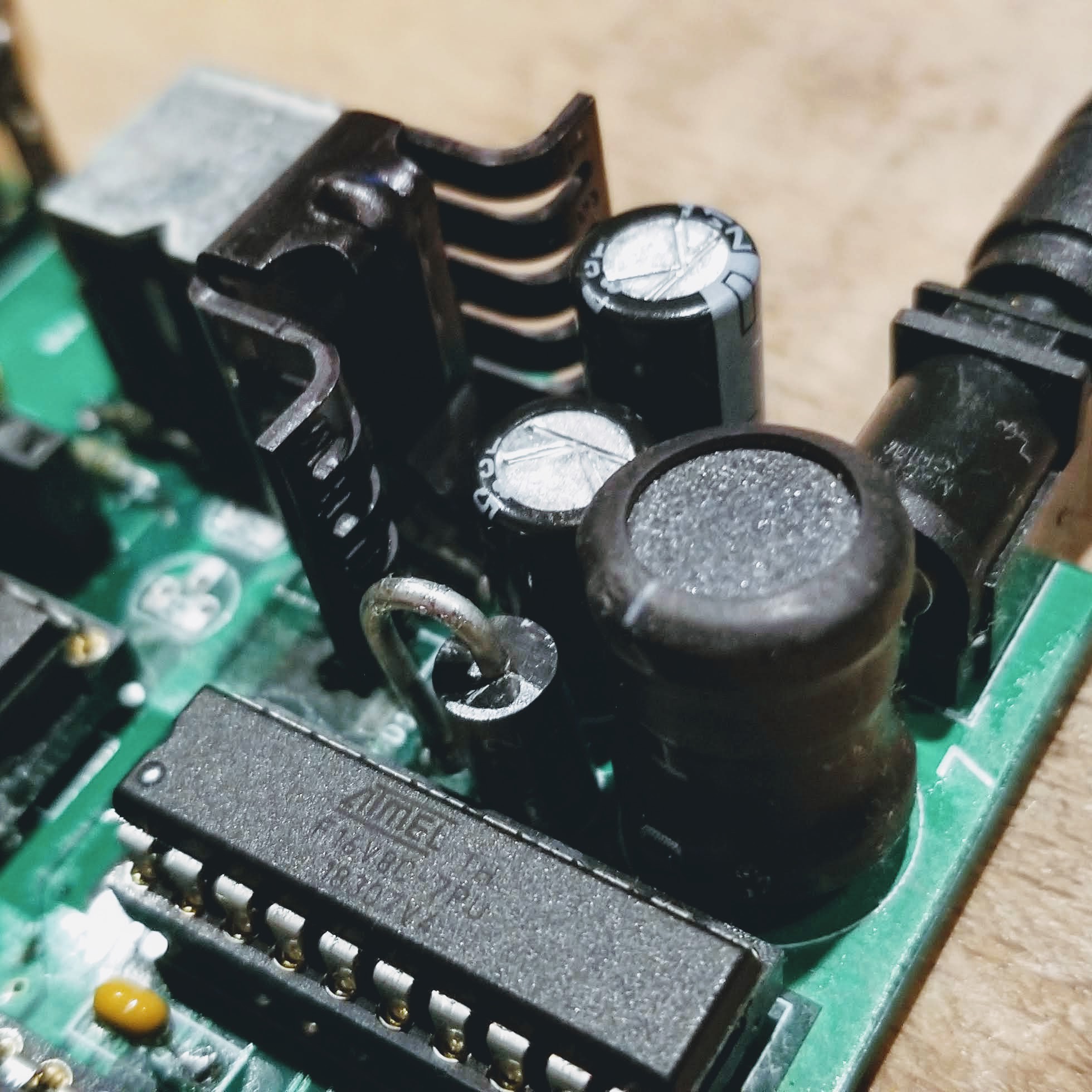
The other major change was the new on-board buck converter. This is working well and provides a clean and stable 5v supply with up to 2A from a lower current 500mA 24v input. The PCB has the wrong footprint for the regulator with the pins staggered the other way (there will definitely be a Rev. 3 board!). The pins were re-bent and everything was able to fit within the one-cubic inch of available space. The regulator and inductor run hot, as expected. The design calculations indicated a 50C rise above ambient under load and this appears to be the case.
The final delta was some updates to the audio circuit. The op-amp was tested under load during the Rev. 1 phase and can easily supply up to 150mA. This is enough to drive a small internal speaker, similar to the old UK home computers from the early 80's (ZX Spectrum, Jupiter Ace, BBC Micro, etc). This is optional and would be supported with a speaker connector and trimmer pot to control the volume (once the correct vertical mounted POT is installed). A fixed resistor can be added in place of the trimmer for a line-level output from the audio jack.

So there's some debugging ahead to work out why the faster clock is not working and why the OTP ROM doesn't work. It's possible that both issues are related, but figuring out the root cause is likely to burn up the entire weekend.
Discussions
Become a Hackaday.io Member
Create an account to leave a comment. Already have an account? Log In.