 David Boucher
Electrically, a keyboard is just a grid of wires with a switch at each intersection. Pressing a key (switch) makes a connection between a single row and column. To read the keyboard, a controller energises the wires in one axis one at a time and checks each wire on the other axis for a circuit. If there is a circuit between a particular row and column then the key at that intersection is pressed (Probably, but I'll come back to that in another log).
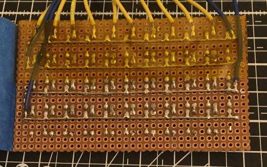
This is the back of my first prototype. Please excuse the terrible soldering and the fact that I totally missed a pin (which I've only just noticed). You can clearly see the row connections connected to the dark blue wires. The column connections are connected to the yellow wires. You don't see column wires running down the board because the columns are connected through the switches. The switches have two pairs of pins permanently connected:
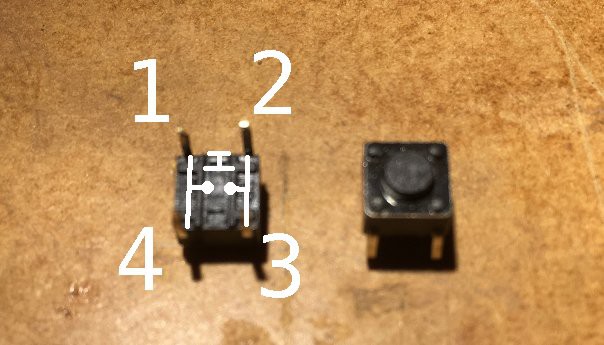
In the picture above, pins 1 is permanently connected to pin 4 and pin 2 is permanently connected to pin 3. Pushing the switch connects all four pins. This means that I can carry the column connections through the switch, bypassing the row wiring. A solder joint across two pads connects each row to the one below it.
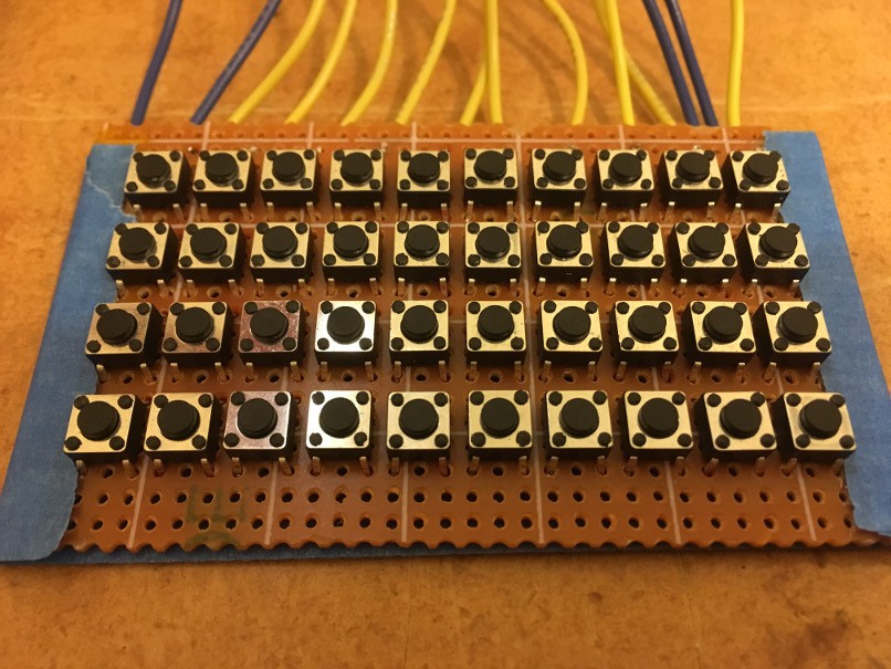
Although my prototype has the keys laid out in a rigid grid, this is of course not usually the case with keyboards. Keyboards generally have their rows offset and include keys of different sizes, which sometimes cross multiple rows or columns. I don't think that different sized keys are practical with my design, but I want to look at offsetting the rows at some point. As this is meant to be a thumb keyboard, not a full sized one, I think that this is an acceptable compromise.
Discussions
Become a Hackaday.io Member
Create an account to leave a comment. Already have an account? Log In.