 David Boucher
I'm going to go over how I assembled the prototype starting with how everything is connected up on the perfboard. I've already covered some of this in the first "Keyboard Basics" log, so this is mainly a recap with some more details.
The perfboard is the standard single sided type with holes spaced at 2.54mm/0.1in. Each switch takes up three holes across and four down and the grid is 10x4, so this gives us 30x16 holes. However, I also want a two holes margin around the whole board which I'll eventually use to help hold the board in a case, so the total size is 34x20 holes.
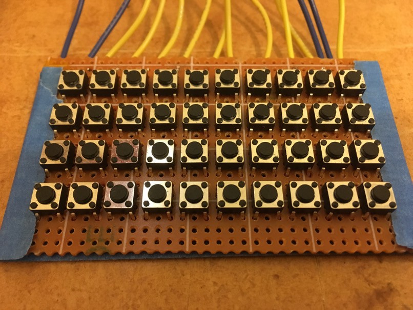
The switches are also a common type sold as "6x6x4.5mm Panel PCB Momentary Tactile Push Button Switch 4 Pin DIP". These fit into the perfboard with the pins facing top and bottom as close as they will go leaving a two hole gap around each edge. It should look something like this. Ignore the blue tape and wires for now:
Then I flipped the board over and folded the left side (as we are looking at the back of the board) pins of each switch outward and the right side ones inward. I made sure that each switch is flush with the board when folding the pins. I used the 3D printed part (which I know I've not covered yet) to check the switches were correctly positioned.
Finally, I soldered the switches as per the picture below. An uninsulated copper wire carries each row connection across the board and the column connections are carried through the switches (as explained in the log I mentioned earlier). In the picture below, I've coloured the row connections blue and the columns ones yellow to make things easier to follow. The uncoloured pins are not connected to anything and are just holding the switch in place. The row and column connections have to be bridged over two pads, which is why the soldering is messy. Well, that and the fact that my soldering is messy anyway.
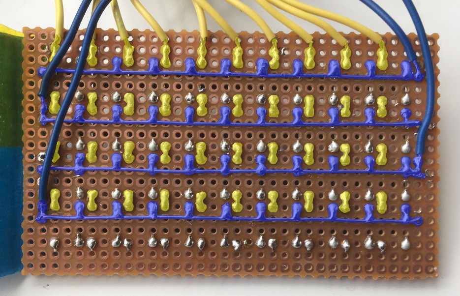
The final bit of soldering is attaching the wires for the rows and columns. I put two row wires at each side to avoid a clump of wires at one end. If you look at the top left corner of the picture above you'll see two pieces of tape. I put a piece of kapton across the board to keep the wires in place and then later added a piece of masking tape (painters' tape) over the whole back side of the board when I found out that my fingers would short out the connections when I was holding it. If I had realised that in advance I could have skipped the kapton and just used the masking tape.
Now we have a keyboard and the code to scan it, but we need to know which key is which, so next time I'll cover making the key labels.
Discussions
Become a Hackaday.io Member
Create an account to leave a comment. Already have an account? Log In.