 Ross Bamford
Handling Reset with the m68K is a little bit involved, and every project seems to handle it in a slightly different way. This log represents the way I've approached it, and it seems to work (right now, that means it successfully gets the processor free-running, has some status LEDs, and when the reset button is pushed it resets the free-run to the bottom of the address-space).
The reset circuit has the following requirements:
- At power-on, the m68k requires us to pull the /HALT and /RESET pins low for a bit.
- It would be useful to have some LEDs showing the status of the reset and whether the CPU is halted.
- Push-button reset is needed so we can, err, push a button to reset the thing.
So basically, I need a circuit that will pull two lines low for a short period at power-on, and additionally allows me to push a button at any point to do the same thing.
This is made slightly more complicated by the fact that the two lines I need to pull low can also be pulled low by the chip itself, to signal to the outside world that a soft-reset has happened, or that the CPU is halted. Just driving the lines high when I want to deassert them isn't going to work here. I'm going to need to drive them with open-collector outputs, and weakly pull them high when I'm not driving them low.
I could tie these two lines together (see http://www.easy68k.com/paulrsm/dg/dg06.htm for example), but if I do that I'm hardwiring the CPU to reset when it halts, which for now wouldn't be an issue, but later on I'll probably want that to not be a thing.
With all that in mind, I put together the following circuit to take care of the /HALT and /RESET lines:
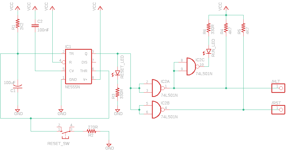
(Caveat: I'm still learning here and am an EAGLE noob, so shout up if I've done anything stupid!)
This is a simple delay-before-turn-off 555 circuit hooked up to the /HALT and /RESET lines via 7400 series open-collector inverters (actually NANDs with the inputs tied together in my case, but only because my awesome local electronics store, https://www.rfpotts.com/, happened to be out of stock of the 74LS05 this weekend).
For the sake of my sanity, and blinkenlights of course, it also has a RESET_LED (in red on my board) that shows when a reset is in progress. This is just driven from the output of the 555. There's also a (green) RUN_LED that is lit when the HALT line is high. I probably could have driven that directly off the line, but I decided to use one of the (otherwise wasted) gates on the 74LS01 to drive it instead.
Both /RESET and /HALT are held low for about half a second at both power-up and on the reset button push. This is way longer than is strictly necessary (about 2M clocks with my current 4MHz clock!) but it gives everything (power supply and clock) plenty of time to stabilise and is hardly noticeable in person-time so I'm not too concerned about it. If I wanted to make it shorter, I could just play around with the values of R1 and C1 until I was happy.
So that's it for the reset circuit. I have a working reset without having the two lines tied together, and the CPU seems happy with it. Next time, I'll show the clock circuit, and then we can get onto talking about the 68k itself :)
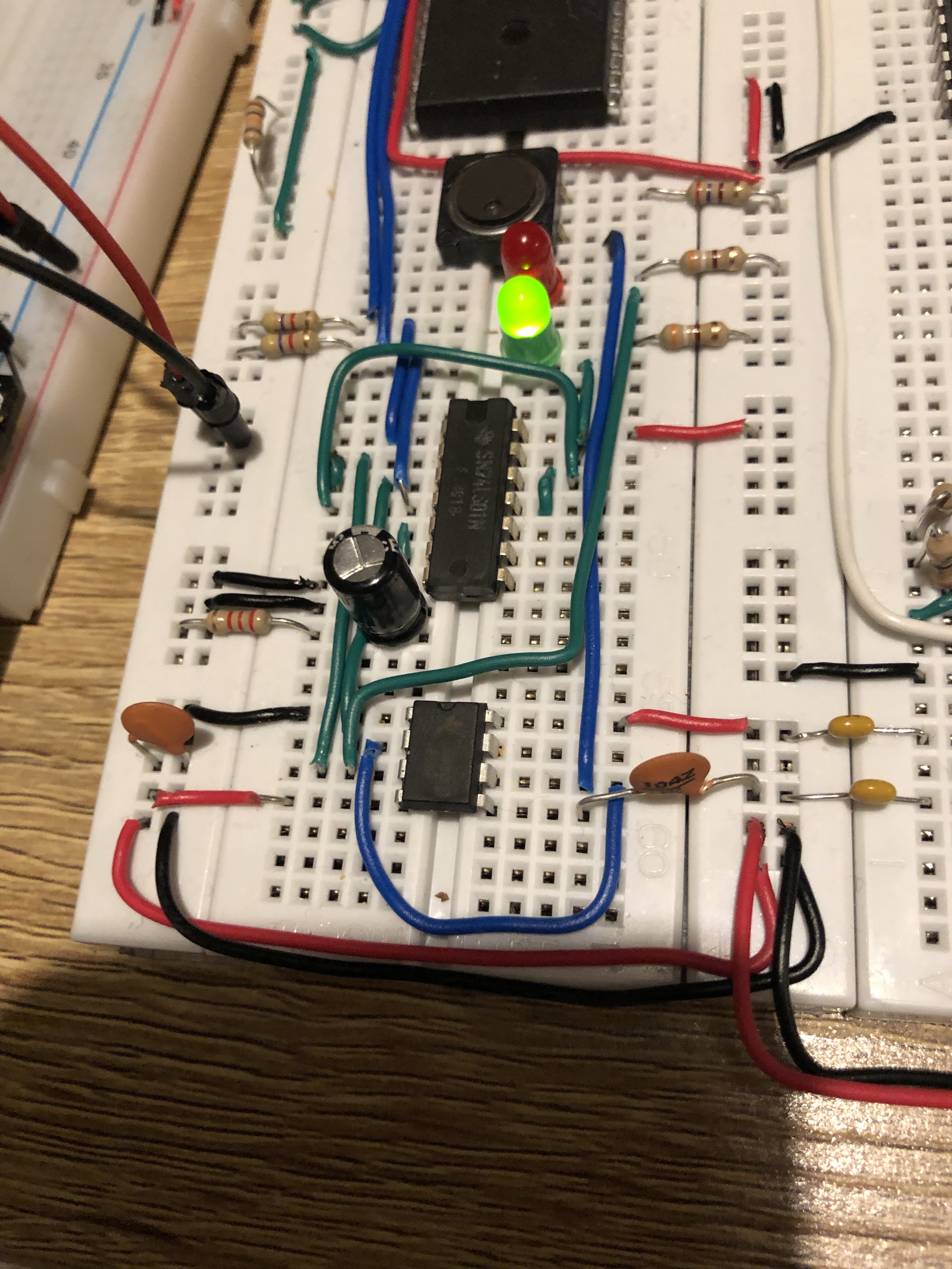
(For completeness, here's the circuit on breadboard):
Discussions
Become a Hackaday.io Member
Create an account to leave a comment. Already have an account? Log In.