 Ross Bamford
For the 4MHz clock circuit on the m68k build, I'm using a simple circuit based on a 4MHz crystal, a few capacitors and resistors, and three Schmitt trigger inverters on a 74LS14.
Looking around the Internet for a suitable circuit didn't really turn up anything I could directly use, but it did turn up a ton of information on the theory of these things (some of which I still don't understand!). This was a Good Thing(tm) as it meant I had to actually figure out how to build a clock circuit for myself, rather than just copying someone elses!
The design I ended up with looks like this:
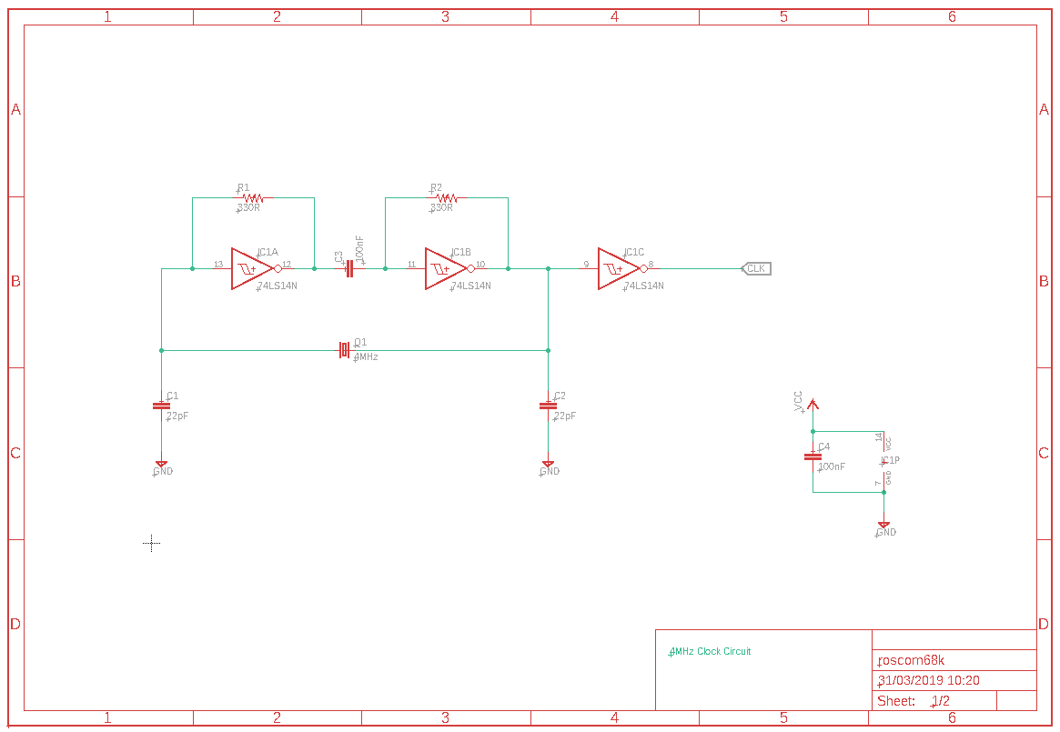
(I know, the names and values should all be the same orientation - I'm getting better with EAGLE but still no pro!)
In hindsight, this is probably more complicated than it needs to be, but it does work. I've also read that it might be a bad idea to use Schmitt trigger inverters for the first two gates in the circuit, as they might fail to oscillate, or oscillate at an unintended frequency, due to the Schmitt triggers making a non-linear amplifier. It works well right now on breadboard but I guess I might need to revisit if I ever build a PCB for this, or when I up the frequency to the 10MHz the m68k is rated for.
Obviously this is my first real attempt at working with a crystal and trying to make a stable oscillator, other than just following someone else's design, and I'm sure it's both non-optimal and not really correct. That's part of the reason the reset circuit holds the reset line high for a relatively long time at power-up (~2M cycles) - to give this thing lots and lots of (read: far too much) time to become stable.
This circuit was easily the most difficult thing I've faced so far with the m68k build, but the satisfaction when it worked and gave a solid 4MHz clock on the logic probe was immense :). Even better was when I left the chip free-running overnight and came back in the morning to find it still happily blinking lights on the top eight address lines.
Here's a shot from the logic probe showing the clock signal:
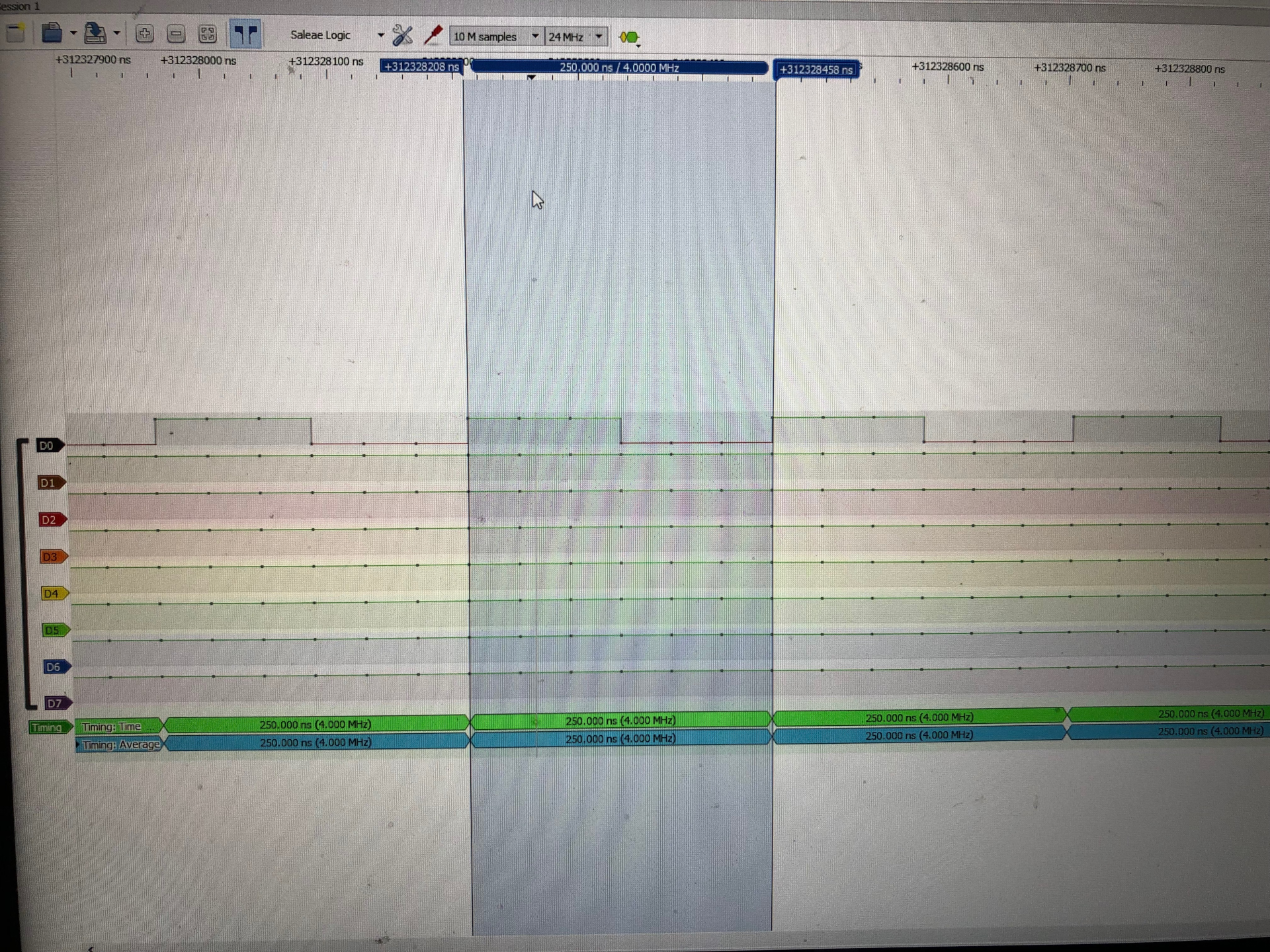
(Yes, I wish I'd cleaned my screen before taking that).
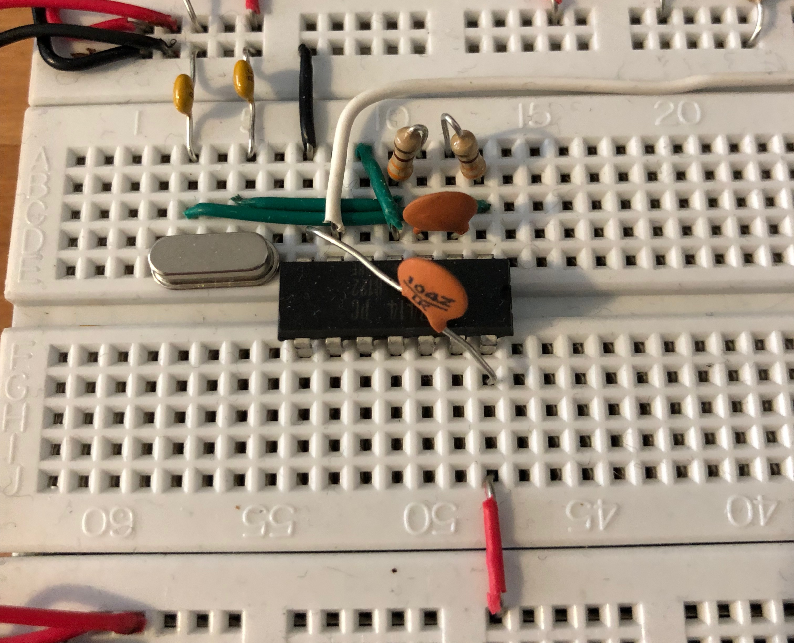
And here's the built circuit on the breadboard:
The next log will be the address decoder, which is designed but not yet built as I'm lacking a few 7400-series ICs it needs.
Discussions
Become a Hackaday.io Member
Create an account to leave a comment. Already have an account? Log In.