0%
0%
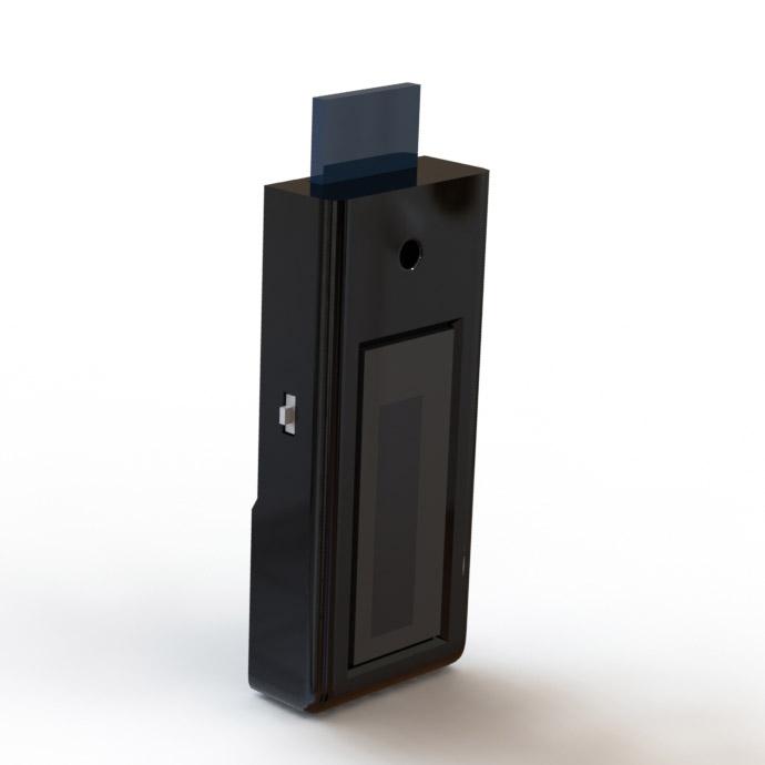
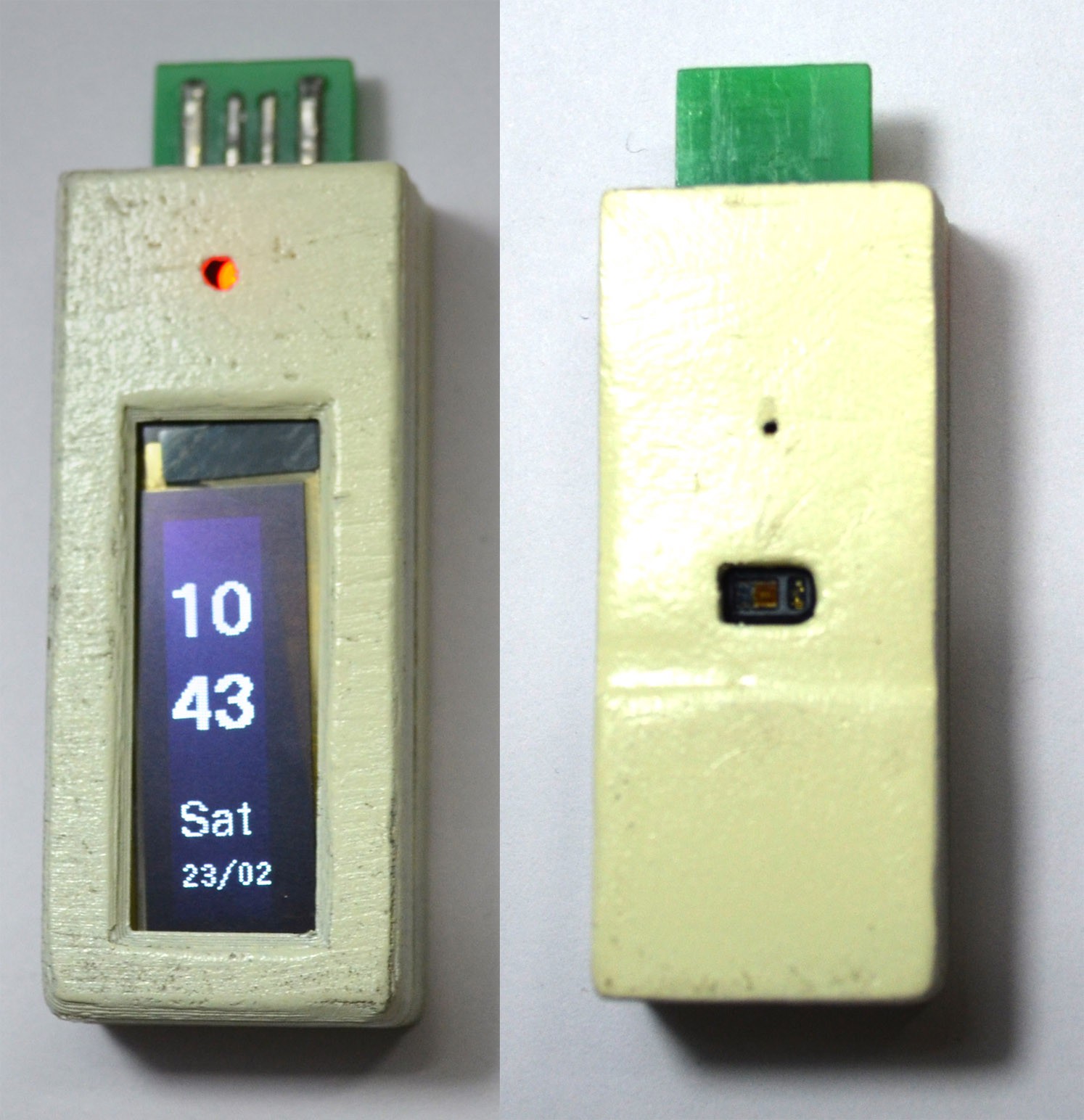
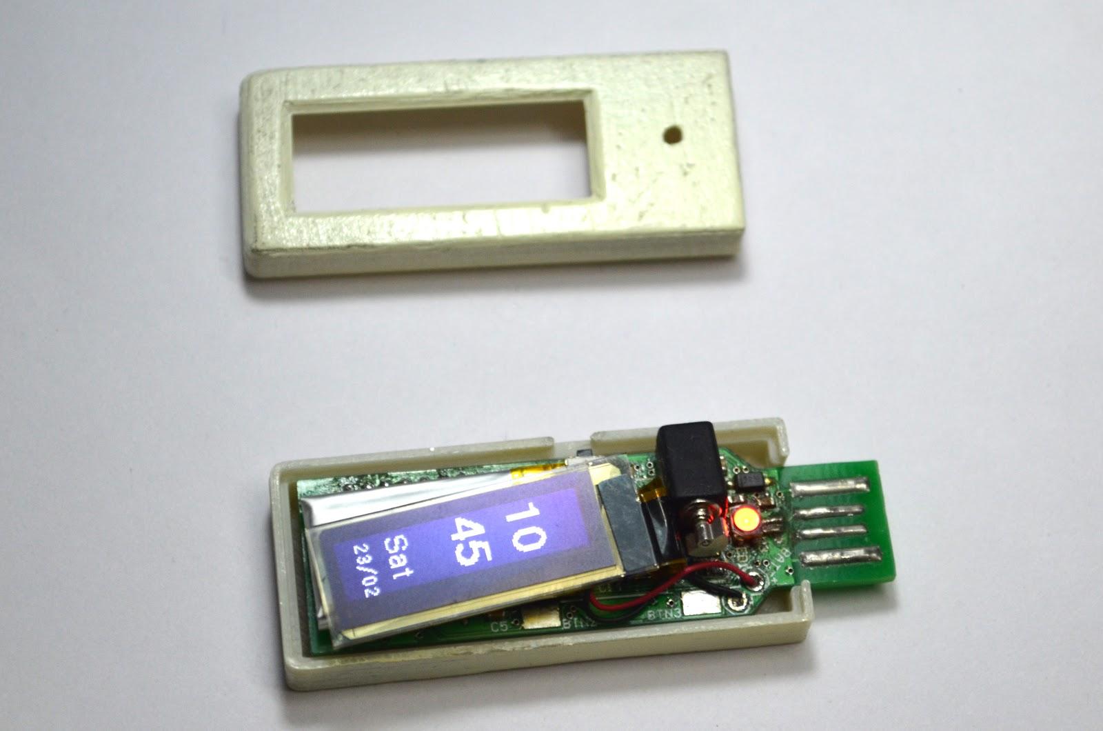
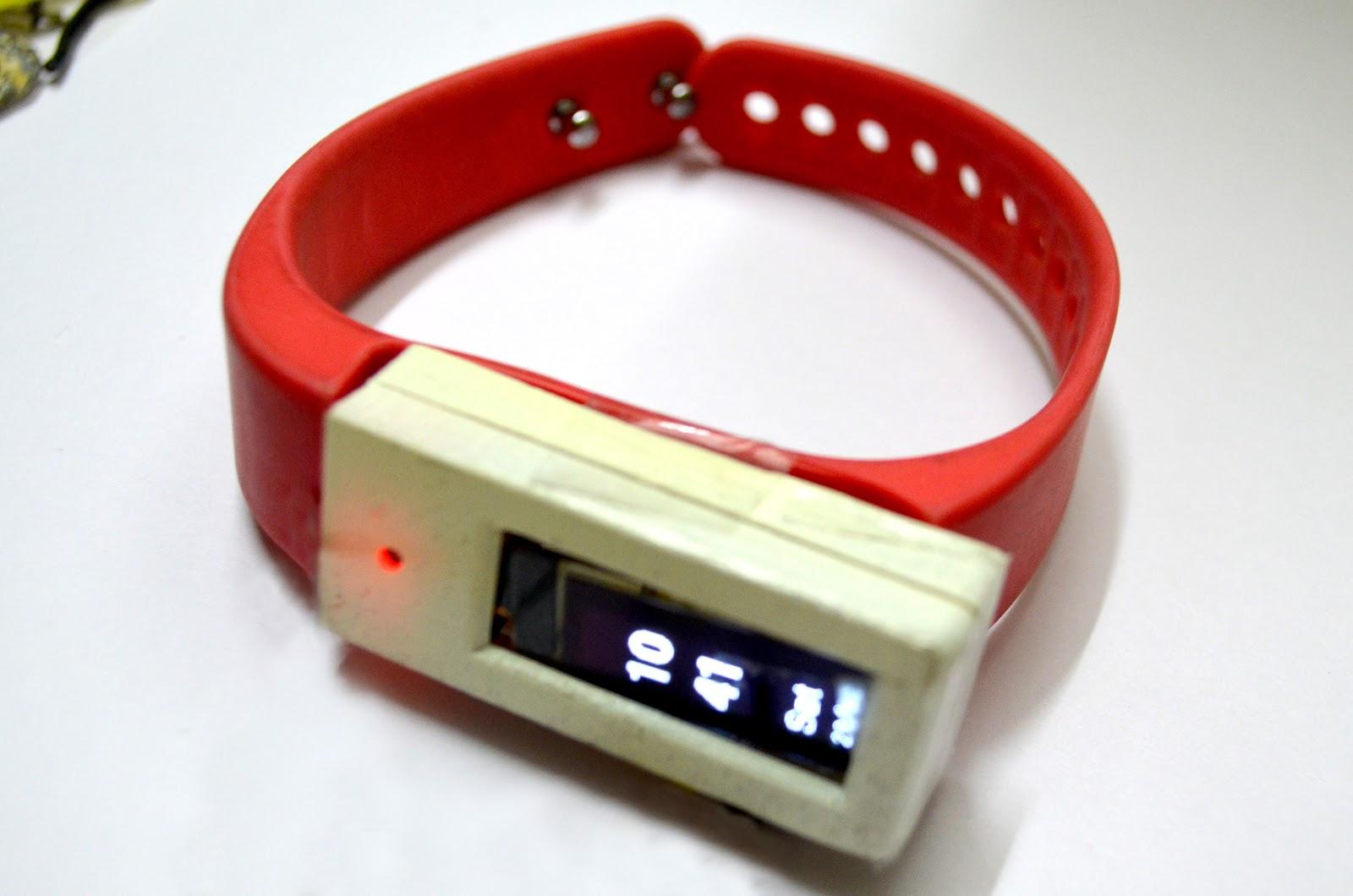
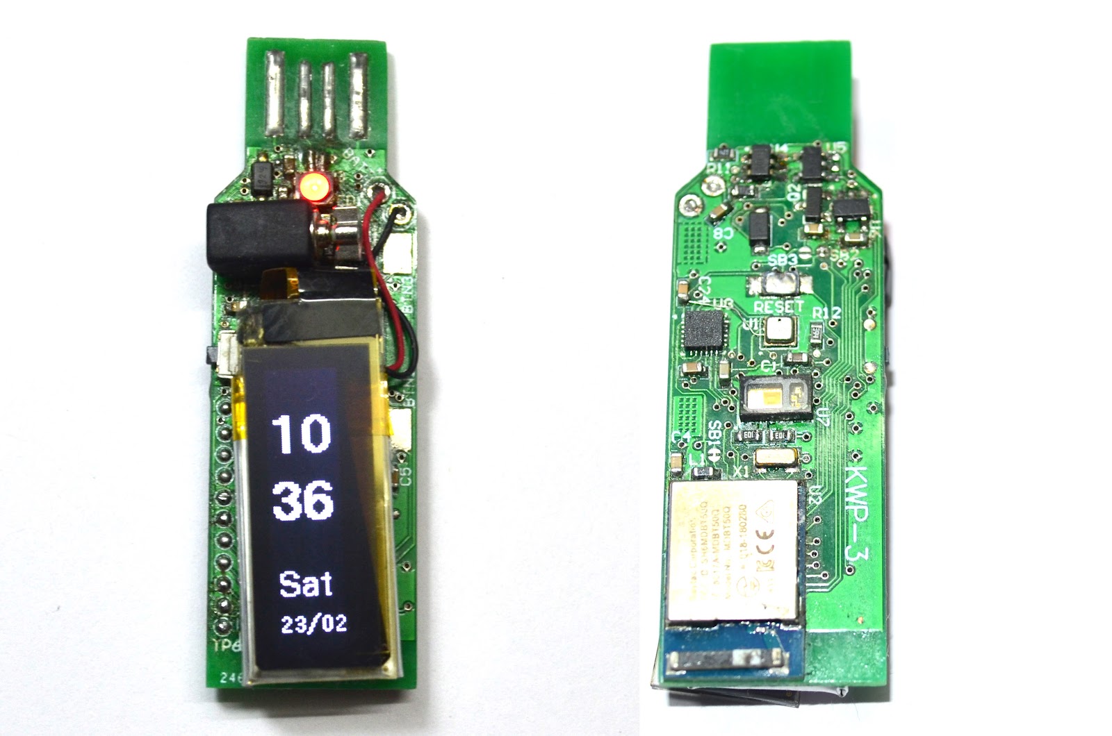
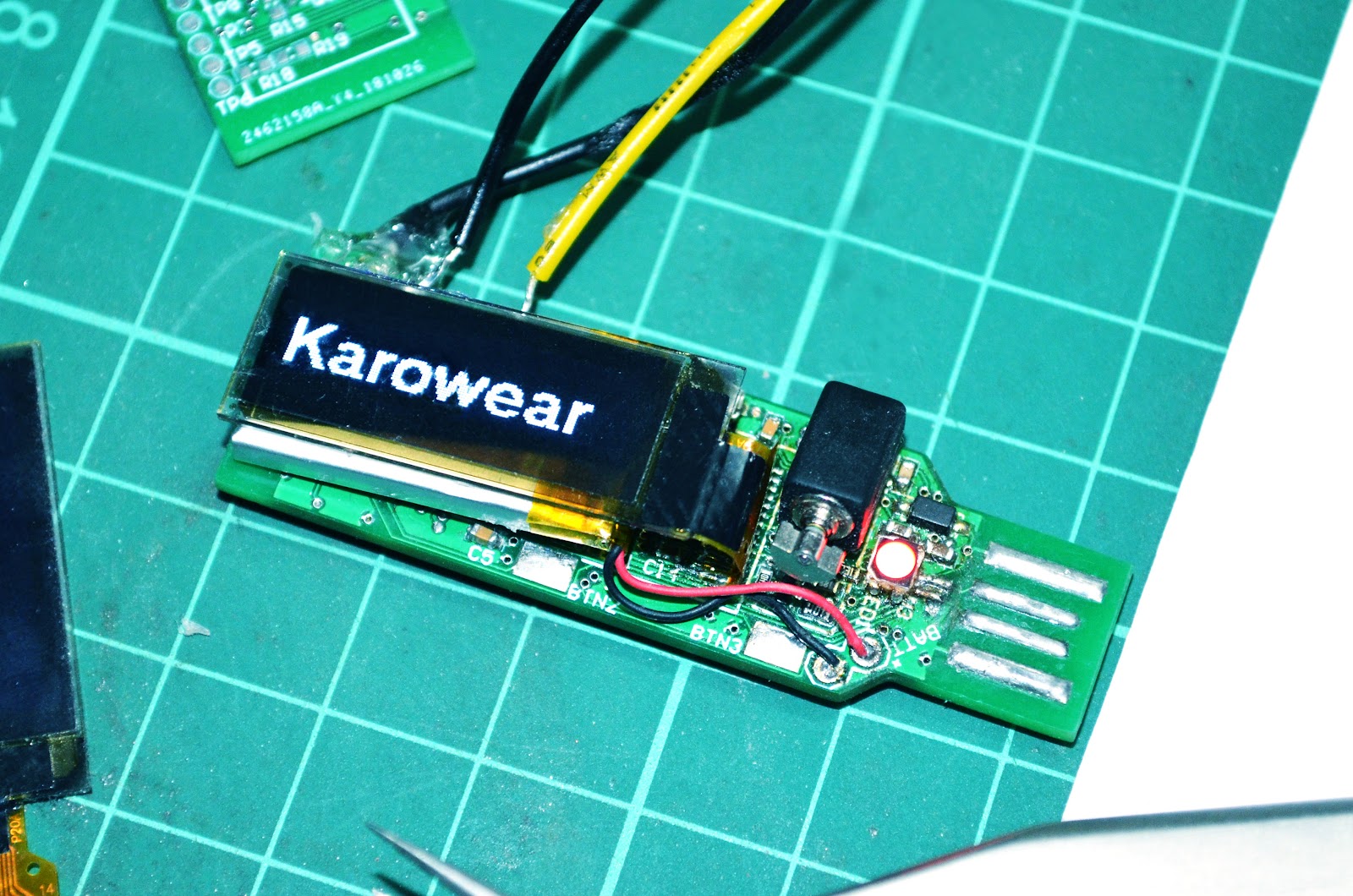
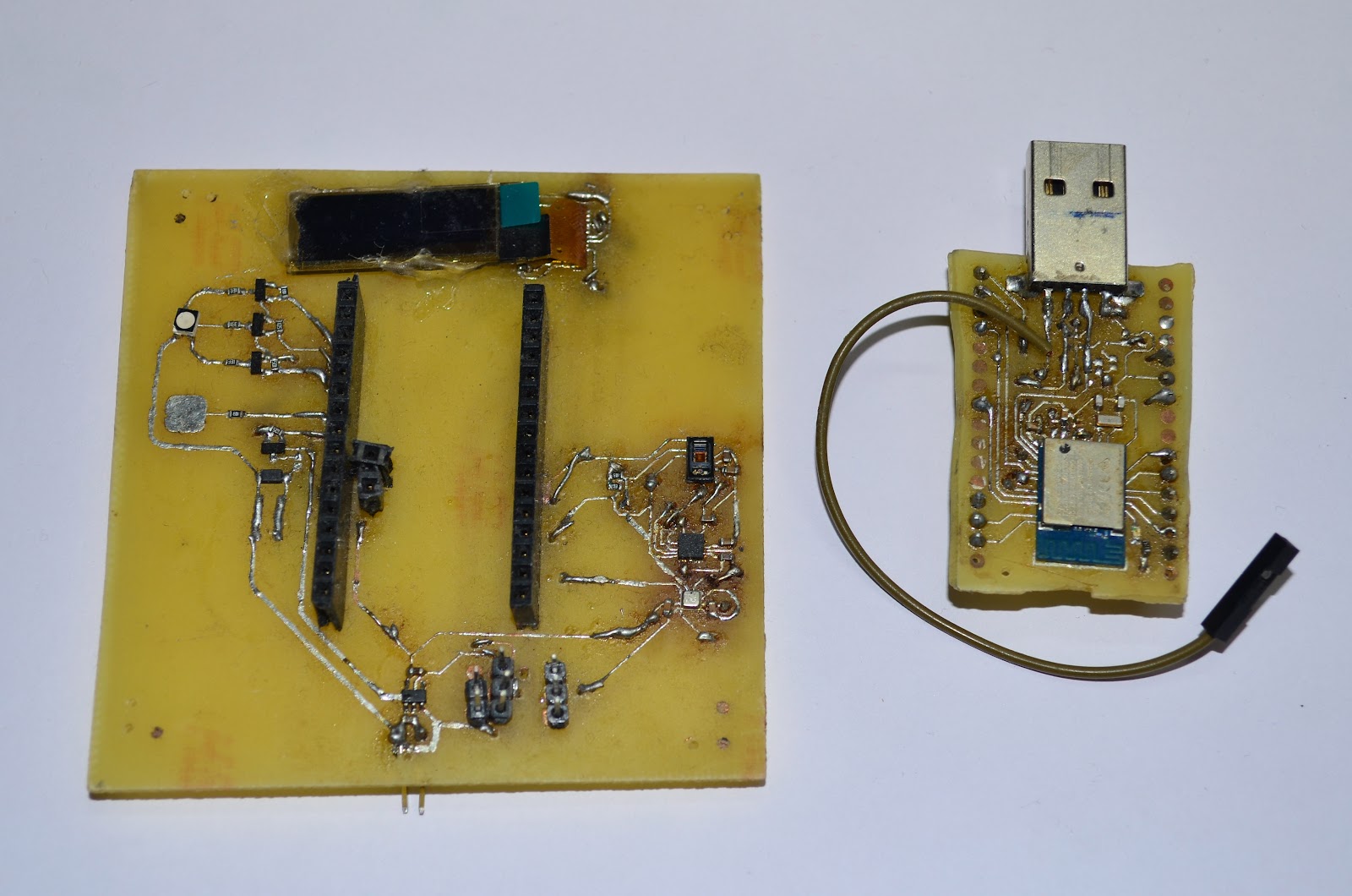
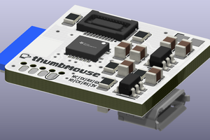
KaroWear
KaroWear is a NRF52840 based watch in a USB dongle form factor with a multitude of sensors.
 Rohit Gujarathi
Become a Hackaday.io member
Already have an account? Log in.
Just one more thing
To make the experience fit your profile, pick a username and tell us what interests you.
Pick an awesome username
hackaday.io/
Your profile's URL: hackaday.io/username. Max 25 alphanumeric characters.
Pick a few interests
Projects that share your interests
People that share your interests

 Matias N.
 Lloyd3000
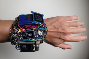
 recursinging
I want to make a similar project. Could you please provide the code?