0%
0%
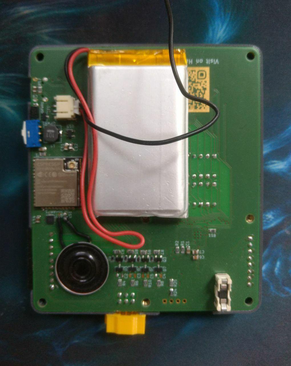
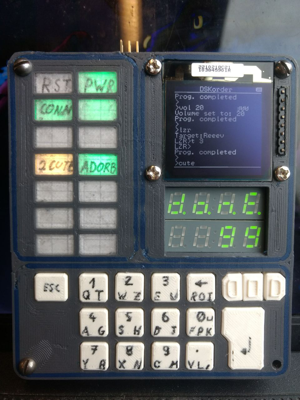
DSKorder
A handheld interface from the future or past.
 Xasin
XasinBecome a Hackaday.io member
Already have an account? Log in.
Just one more thing
To make the experience fit your profile, pick a username and tell us what interests you.
Pick an awesome username
hackaday.io/
Your profile's URL: hackaday.io/username. Max 25 alphanumeric characters.
Pick a few interests
Projects that share your interests
People that share your interests


 Max.K
Max.K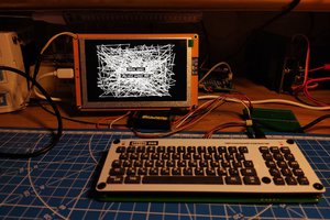
 svofski
 Stephen Holdaway
That is so way up there on my cool-meter :-D