 Zapp
ZappThis is our third year utilizing Macrofab as our PCBA. Each year we've improved our own production process to identify failures as close to the badge production as possible. A major part of this is providing Macrofab with the tools they need to quickly flash and test badges.
This year we sent them a virtual machine (with OpenOCD), STLink V2 clones, and Tag Connect 2050s. The VM was pre-configured with the test firmware and tools to get the job done. A standard feature in our DC26 and DC27 badge is a Power on Self Test (POST). This year our POST tests the capacitive touch controller, internal file system, and LED driver. Any failures during POST results in a flashing green LED. After flashing each badge Macrofab simply needed to observe the green LED and LED matrix to know if the badge is functional.
Initial Failures
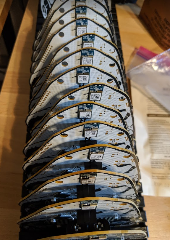
This year we manufactured 600 badges. Of those, 28 failed tested at Macrofab that they were not able to correct. Below is the breakdown of what they found:
- 10 unable to flash
- 4 LED matrix flashing too fast
- 10 LEDs do not light up
- 4 Some other POST failure
Less than 5% failure, not bad, but not great either.
Triage
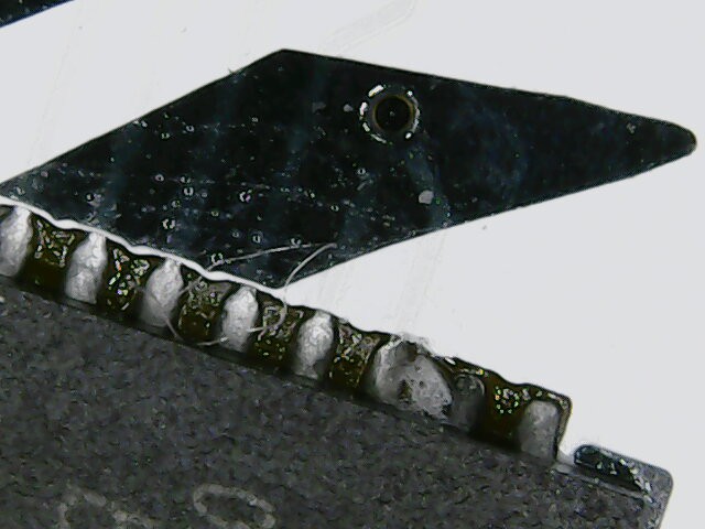
Zapp spent the better part of a day testing each failed badge. Initial thoughts were that the LED driver, a massive QFN60 IC, had shorts between pins. Our DC26 badge had issues with this due to our paste layer. It's relatively easy to correct. The first badge triaged backed up this assumption. After a little touch up with a soldering iron, Zapp had a working badge. Note the extra solder blob between the pins.
This assumption was quickly proven wrong, however, the second badge had a POST failure. Logs indicated a IQS333 failure (capacitive touch controller). The IQS333 is also a QFN part, but not as large. No amount of touch up on the IC helped resolve the issue. In fact it would occasionally correct itself then fail again.
Zapp continued through the badges marking badges with failed LED drivers and/or failed captouch controllers. The LED matrix flashing too fast issue was quickly resolved with a flash of production firmware, however, all 4 badges were found to have capacitive touch failures.
During the triage Zapp found a new failure mode which turned out to be a gap in the Macrofab test coverage, oops! Serial to the FT2232 was not tested. On 6 of the 28 badges serial was not functional.
By the end of triage, failures were further grouped as:
- No Serial (6 of 28)
- No LEDs (13 of 28)
- Capacitive Touch Failure (6 of 28)
- Cannot flash (10 of 28)
Many badges had multiple failures, womp womp
BMD-340
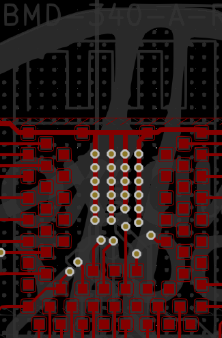
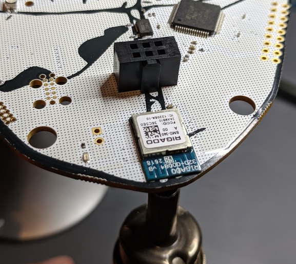
With triage complete, Zapp started on the badges that could not be flashed. The BMD-340 module is connected directly to the SWD and Tag Connect headers, see schematic below for Tag Connect breakout. In fact the traces are very short on the PCB as well. This likely means the module did not reflow properly.

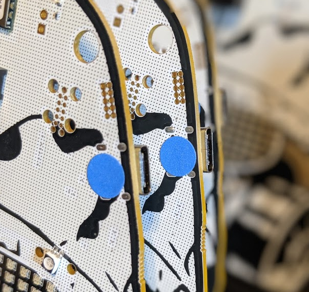
The BMD-340 is a very complex footprint. 65 pins all under the module with 0.5mm pads.
We decided to sacrifice one badge to investigate, using hot air from the bottom of the PCB, Zapp removed the module.
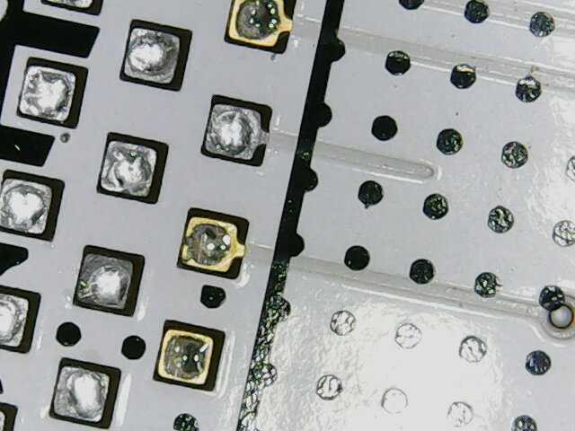
What Zapp found was insufficient solder on the SWCLK pin.
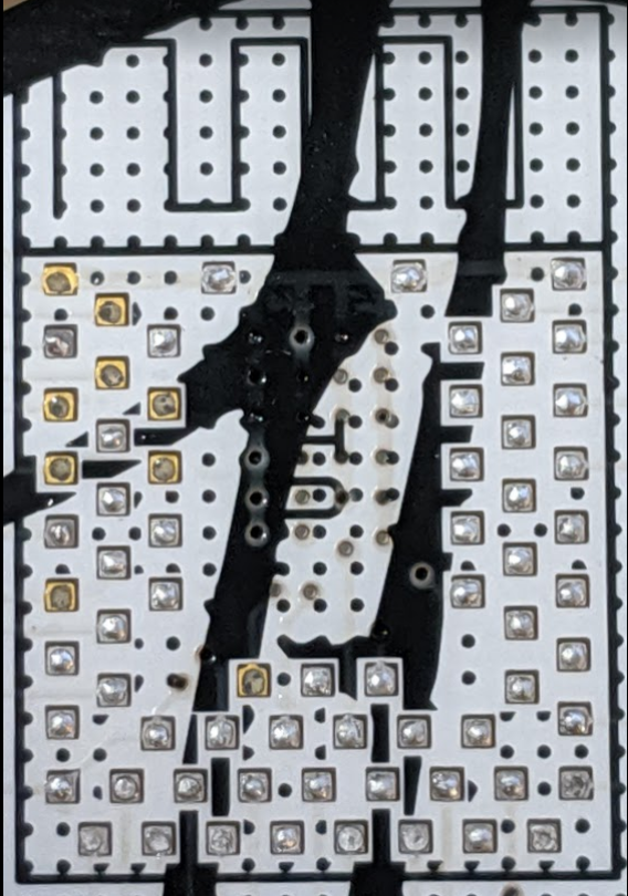
What Zapp also found was his hot air was set *way* too high. Getting this right is harder than it sounds. Macrofab uses a lead-free process which requires a much higher temperature to melt solder. However, the only way to heat the board is from underneath the PCB. Zapp eventually dialed this in but a couple boards have some burn marks, sorry!
With the root cause identified, the hard part was to come, resoldering the modules. To do so, Zapp applied some rosin flux (the good stuff) then using a soldering iron and some 63/37 solder applied tinned each pad on the PCB. It is important to ensure each pad has the same amount of solder to avoid issues. Zapp repeated the same process to the underside of the module, leaving some flux to help with the heat transfer when reflowing.
The final step is the reverse of the first, position the module (it can be off by a mm) on the PCB, apply hot air to the underside for about 30 seconds. The 63/37 solder has a lower melting point. Once the solder melts the module snaps into place.
After cooling, Zapp was able to flash the badge and all is well after some cleaning. Zapp then repeated this process on the other 9 badges that failed flashing also recovering those.
Moar BMD-340
Next was to debug the capacitive touch and LED driver issues. After touching up the QFN pins and still nothing working, Zapp found that the SDB pin was not being pulled high by the BMD-340 which would enable the LED driver. Given the previous issues with insufficient solder, Zapp removed the BMD-340. Same issue as the SWCLK pin, this time on the pin used to pull SDB high. Sigh...
Same process as before and all of those were recovered. Additionally, the capacitive touch controller was also fixed due to its RDY pin not being connected from the same issue.
After 2 days of triage and BMD-340 reflow, Zapp had 3 badges left with failures that were still not functional.
Serial Issues
The last 3 badges would not come up on USB. In our badge design the FT2232 handles the USB regardless of the BMD-340 status. In the case of these 3, Linux dmesg complained about a bad USB cable. Zapp checked the 12mhz crystal and touched up the FT2232 IC, still no dice. After looking at the badge under the AmScope he discovered a a very tiny short between pins 3 and 2 on the ESD protection IC (U2) effectively shorting the USB D+ line to GND.

A quick touch up with the soldering iron on all 3 badges and they were good to go!
Summary
While 5% failure rate may not seem that high, it has an impact on the overall unit cost. By providing Macrofab with the ability to flash and test the badges on the line we avoided a good number of failures. However, the gap in our test coverage meant failures related to serial may have slipped through. Fortunately our team still has to do its own quality control and final firmware flashing that will catch those issues before they make it into the hands of hackers.
We provided feedback back to Macrofab, at this time we're not aware of any design issues with our PCB. The BMD-340 solder issues may just be a function of the very small pins underneath the module. In the future we will avoid such modules so visual inspection (even with a scope) can catch the issues and simple hand soldering can correct them.
Bottomline, all 28 were fixed however 2 had burn damage to the PCB itself while Zapp was finding the ideal temperature for his hot air. We'll tag these as such and hope to find a good home.
Discussions
Become a Hackaday.io Member
Create an account to leave a comment. Already have an account? Log In.