 Hyr0n
Hyr0n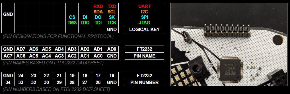
Introduction
One of the functions we were most excited about including in this year's badge was an FTDI 2232H with breakout such that it could be used as a hardware hacking tool. Hack the other badges, IoT devices, embedded systems of your choice... Hack The Planet. Think of this like a Bus Pirate, however instead of a clunky embedded CLI you will be using software on your computer to interface with it.
Many folks hear FTDI and just think of a serial UART to USB adapter. That's the 232R. However the FT X232H series can be used for a LOT more. For reference the "X" in the prior "X232H" that I mentioned refers to the number of channels on the chip. A standard "232H" has a single channel, a "2232H" has two channels, and a "4232H" (you guessed it) has four channels. By a channel, what this really means is that IC has an independent functional module performing the capabilities described in the data sheet. Our 2232H is like a two in one!
Since we have a two channels on the "2232H," the first channel "A" we dedicated to the hardware hacking breakout (and to be compatible with applications which may only look for the default channel), where as the second channel "B" we integrated as our badge SoC's serial UART interface for the embedded terminal (BOTNET, BENDER). So when you plug in the badge to a computer, you will get two devices.
On a Linux System...
- Channel A (Hardware Hacking) - /dev/ttyUSB0
- Channel B (Serial Terminal) - /dev/ttyUSB1
On a Windows System...
- Channel A (Hardware Hacking) - COM (N)
- Channel B (Serial Terminal) - COM (N+1)
Note that Windows keeps track of permanently assigns virtual COM ports to every serial device it ever interfaces with. So (for example) if the badge is the 45th device ever plugged in, Channel A = COM45 and Channel B = COM46 ¯\_(ツ)_/¯
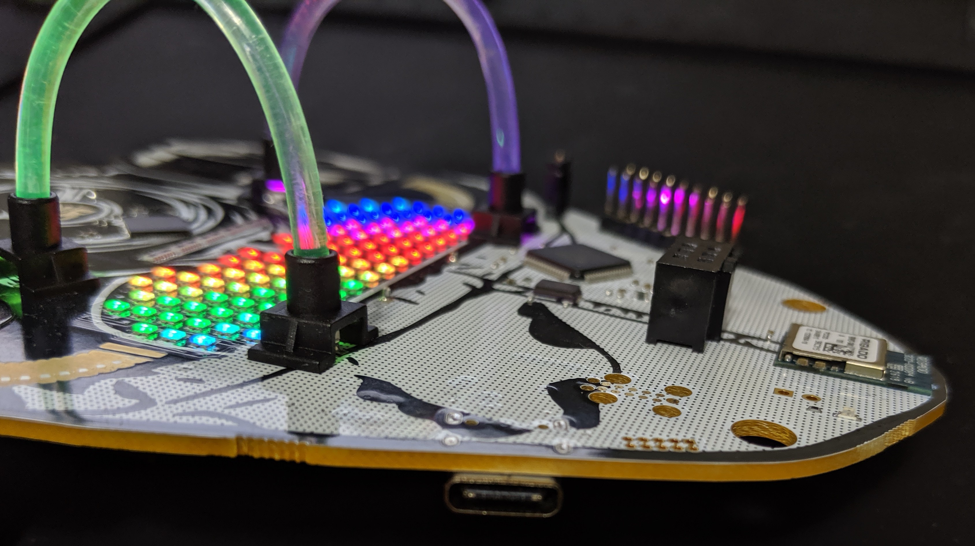
Also, bragging rights... based on our extensive market research (using Google while drinking) this badge is the FIRST USB-C based FTDI X232H Debugger / Hardware Hacking tool out there! No more three tries to plug in your USB cable and it has bling to light your path. Yep, let that sink in.
AND!XOR = King of Shit Mountain
But if change scares you, or living in the past with comfortable hardware interfaces toots your fancy, here's a USB C to Mini Adapter
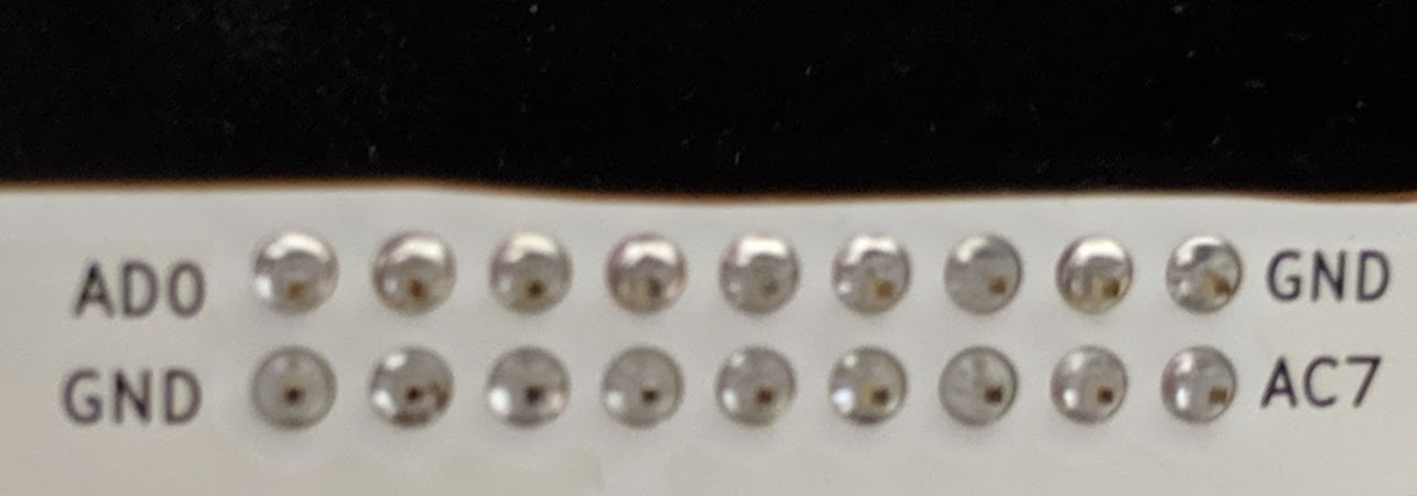
Reading The Legend
The legend at the top of this log is meant to be there as your quick reference. Visually line up those 9x2 cells of information with the 9x2 breakout pins on the badge. This is how you know what to wire up. Right off the bat, you probably think, "Uh... I only need the pins on the top far right like 90% of the time." The answer to that is usually going to be "Yes...but..." there is a lot you can do with this beyond the quick and dirty which would require the other pins (such as bit banging). Also before we go any further, here is a silk screened reference on the BACK of the badge (which makes it opposite) so if you are ever confused you can map up the pins with the legend above.
So to really understand the tool you have in your hands, you need to RTFM. There's so much in there and reading the data sheet will give you the boiler plate knowledge necessary to use it. But if you're gonna be lazy... TLDR (these tables are how those pin numbers and names map up to functionality)
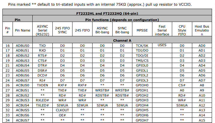
As you can see, each pin function has a lot more optional capability that we listed in the quick reference legend; e.g. ASYNC Serial RS232 supports the full specification with RTS, CTS, DTR, DSR, DCD, and even has options to break out pins for options Tx and Rx blinky LEDs. Very cool, but not 100% necessary. Use the data sheet (or be lazy and look at these tables).
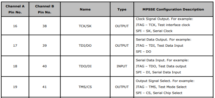
(Ignore the Channel B Column, we used Channel B for our Badge's Serial Interface)
The data sheet contains subsections to show which pins for MPSSE allow JTAG and SPI as well.
Learn By Doing Hacking
So we could just talk about data sheets all day OR we could just show you some hands on examples to get you comfortable and started. Let's do the latter. Also, in case you are wondering why we chose the pin out we did (shifting the bottom row over by 1 and staggering GND), this was for re-use of a standard Saleae probe bundle as well as general disagreement between Zapp and Hyr0n about which end GND should be on (closest to vs furthest away from your commonly used functional pins). Compromise prevails!
Warning: Before we get started know this, you have a chance of permanently destroying whatever it is you are trying to hack. Hacking hardware involves learning and the best kind of learning comes from making mistakes (and magic smoke). But you are reading this on Hackaday, so we assume you're on a quest for knowledge and up to the challenge of destroying 10 things to learn how one worked. Proceed at your own risk.
Asynchronous Serial Example
Requires
- Target Device with Serial Interface
- Three Wires (TX, RX, GND)
- Serial Terminal
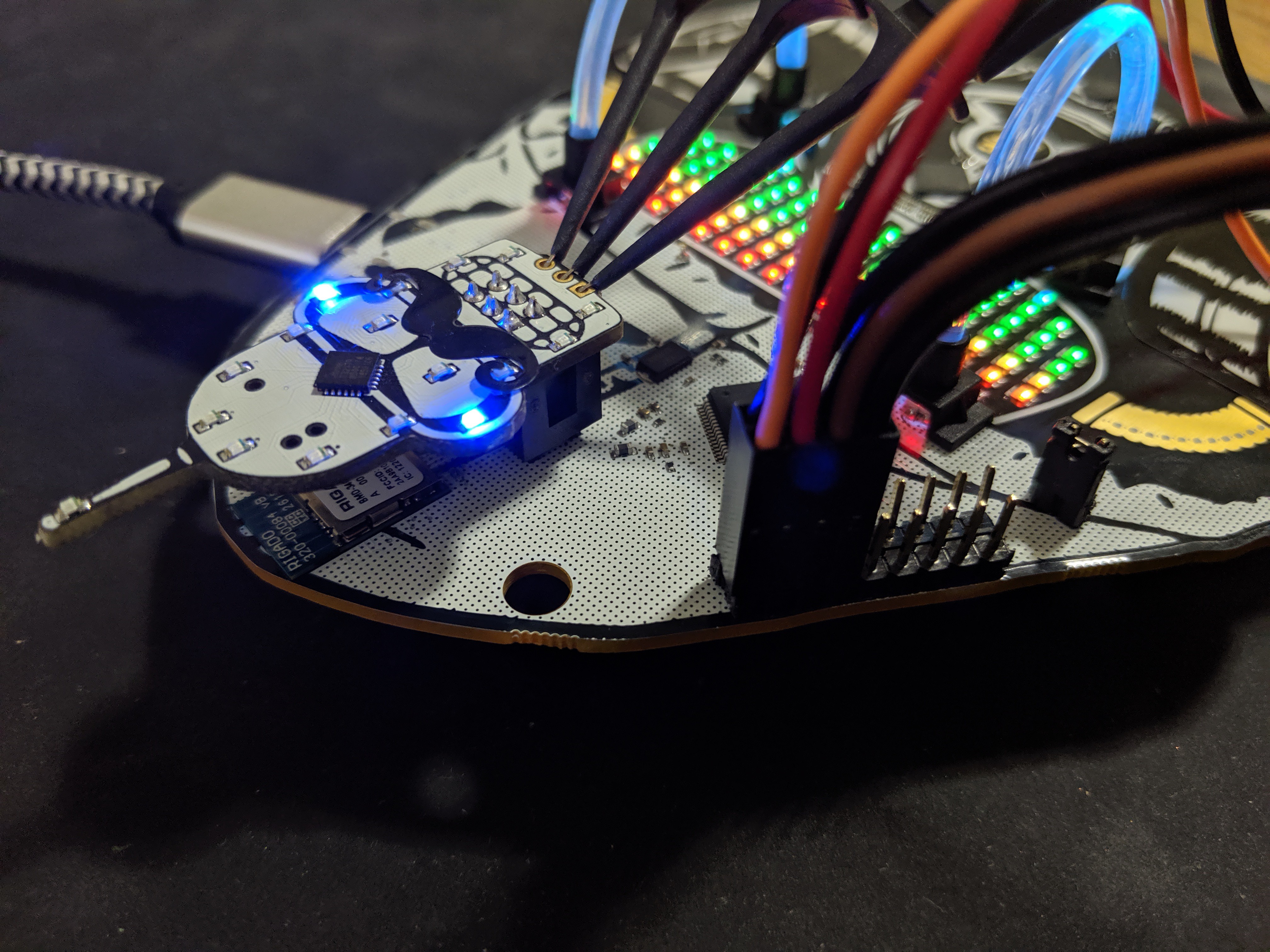
Here we have connected the following...
- FT2232 TX ~ PIN16 (ORANGE) to the Bender SAO RX
- FT2232 RX ~ PIN17 (RED) to the Bender SAO TX
- FT2232 GND (BLACK) to the Bender SAO GND (note this isn't necessary because they already have common ground but is good practice)

Another angle for clarity...
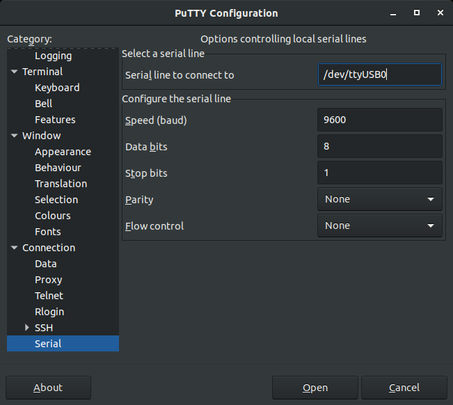
Now since we created the Classic DC24 Bender SAO to have an embedded UART pinout (like the original badge where the USB interface was), we already know the Serial settings (9600/8/N/1). If not, use a JTAGulator to figure it out. So now lets setup our terminal...
Connect and we see...
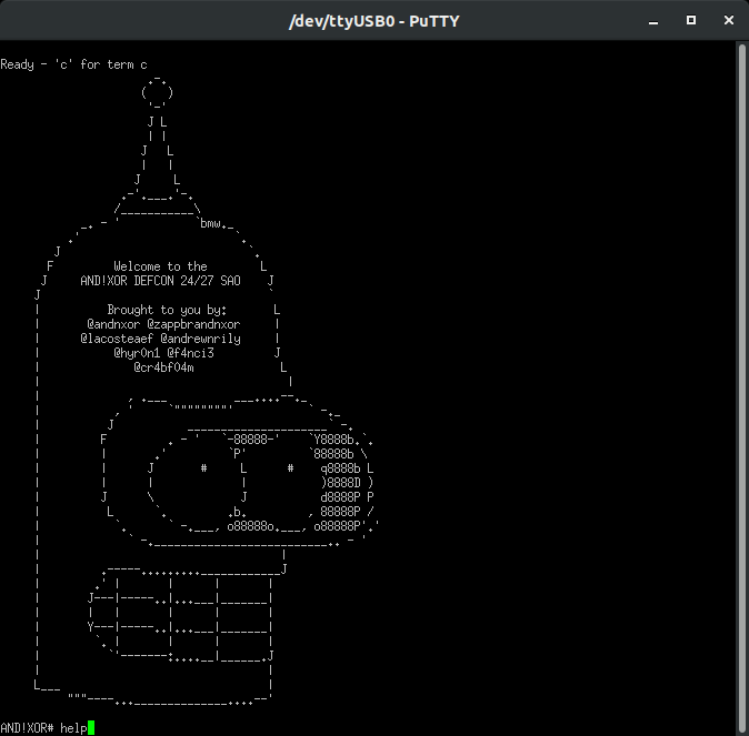
Well there you go! But you may be thinking...C'mon...do I really need a Serial UART adapter conveniently on my badge at DEF CON?
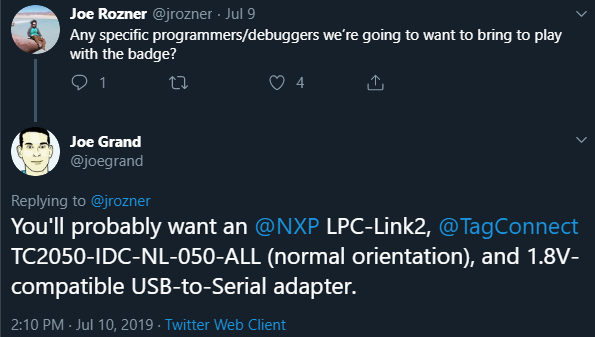
Shamelessly flood Twitter hacking the DEF CON badge with our badge :)
But take SPECIAL NOTE to what Kingpin called out: 1.8V Serial Adapter
The FTDI 2232 runs at 3V so you will need to put a logic level converter in line to convert the 3V -> 1.8V
Dumping SPI Flash Example
Requires
- Target Device with SPI Flash Module & Data It's Data Sheet
- Five Wires (CLK, SDI, SDO, CS, GND)
- Three Wires for Power (Optional if not in device hacking)
- Flashrom (sudo apt-get install flashrom)
Before we get started, watch this quick video from Deral Heiland (who also is an awesomo hardware hacking madman that enjoys reballing BGA with tweezers in his free time)
https://www.youtube.com/watch?v=ZCeisJ4zWp8
This calls out the Shikra (which Hyr0n owns and has used for a while). But guess what makes the $50 Shikra special, or the $15 Adafruit FT232H breakout, or the rando Ebay $4 FT232H breakout special, or our FREE badge for hackers special... they all use the same FTDI X232H :) (derp)
For a target we used a TP-Link (TL-WR841N). For the love of god do NOT use this as your home router...
By the power of screwdriver we got it open and look!
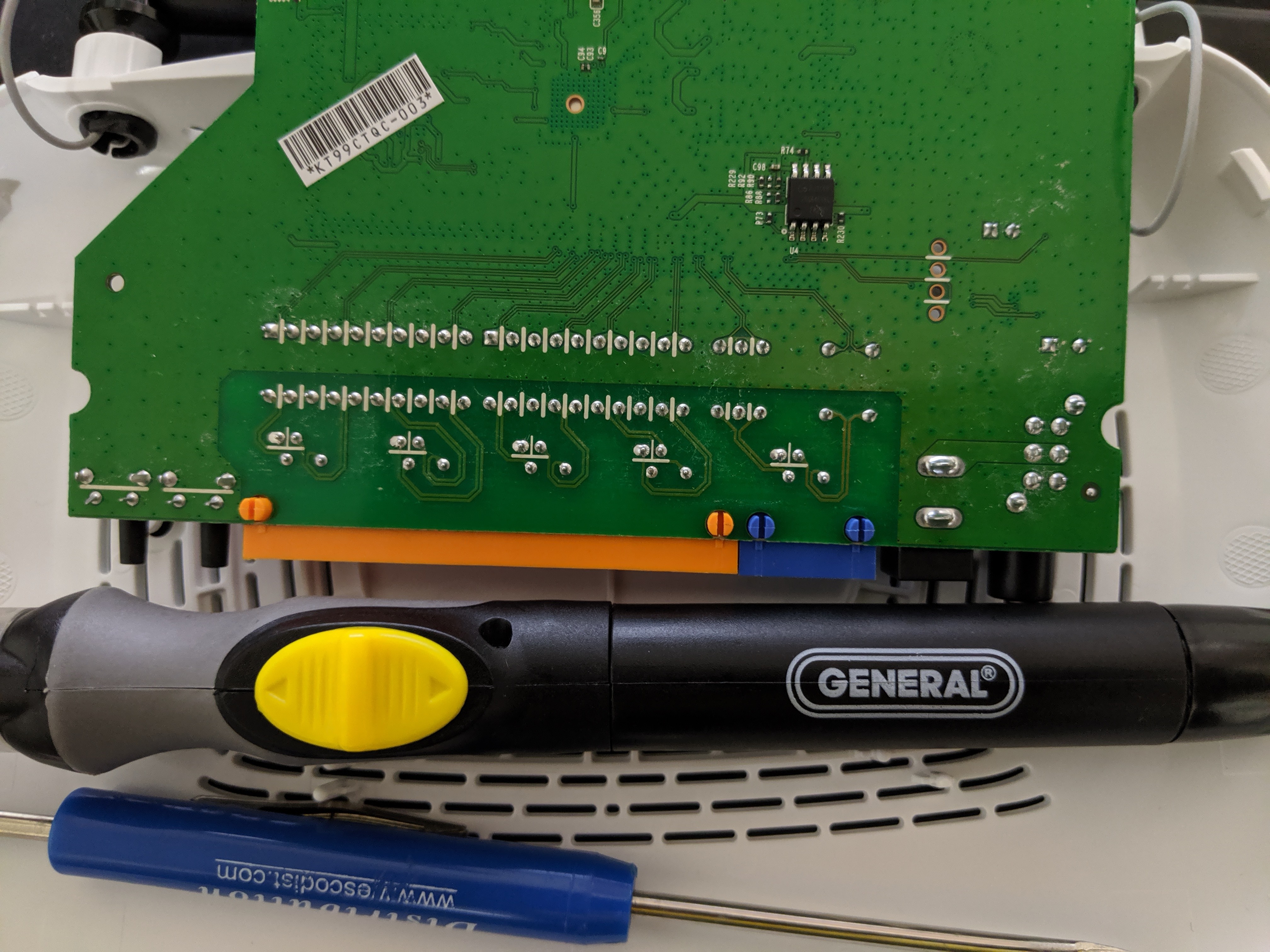
Actually SPI flash is fairly common on most home networking and IoT devices. In the reveal trailer we used an SOIC 8 pin clip (which are nice) however you have to remember to take the target device's MCU and hold NRST to GND to put it in a comatose state (otherwise it will grab control of the SPI flash and you won't be able to dump its contents). To make this example cleaner, I de-soldered the chip and put it on a target board. The trade off with this method is that (as Darel showed in his short tutorial) you have to provide external power to the flash modules VCC, HLD, and WPX pins. But it's cleaner and usually faster than figuring out how to sleep the target systems MCU (and not damage it). Also, SOIC-8 clips are useful for about < 10 times, then the contacts get wiggly and stop working well.
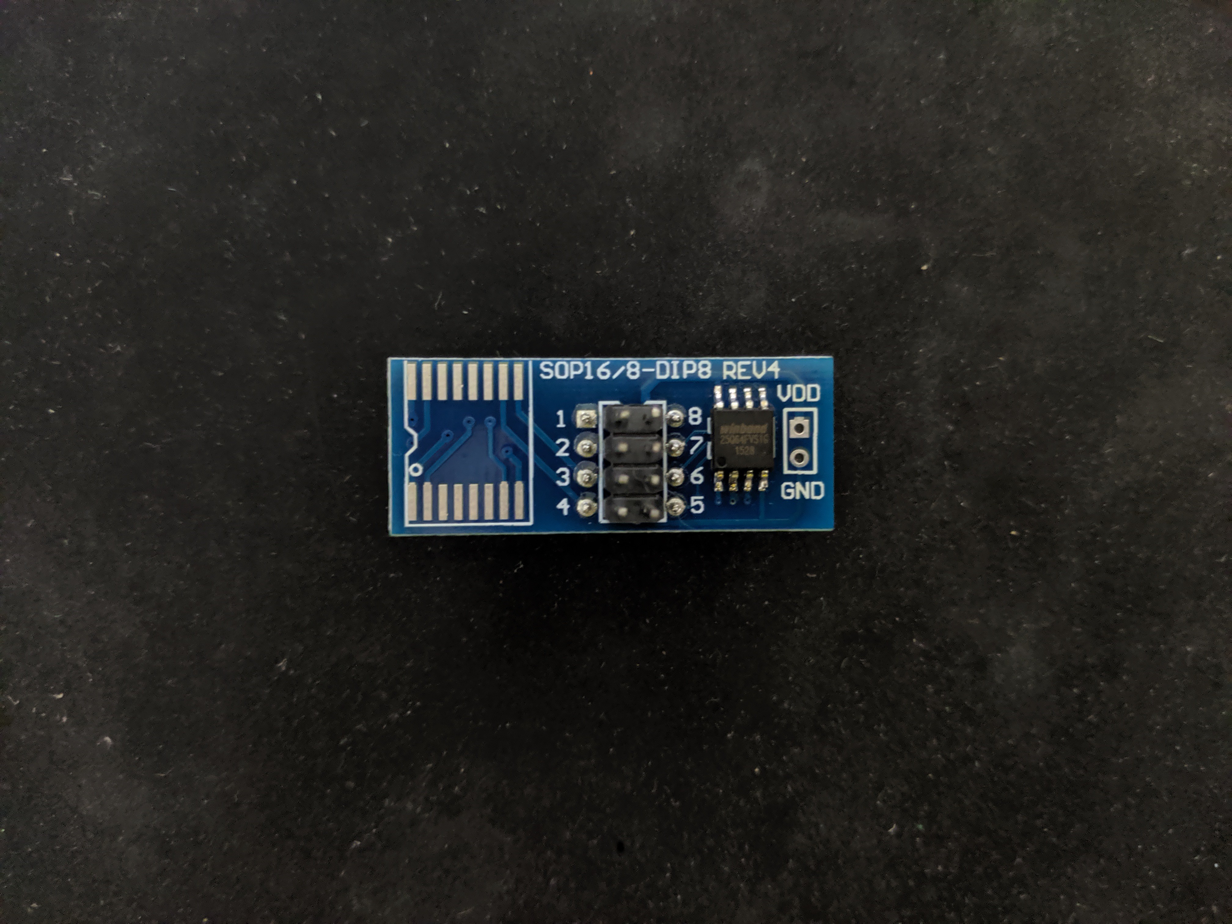
Let's Google the chips code and find its data sheet: W25Q64
- Winbond W25Q64 SPI Flash
- Data Sheet
This is actually very common and a lot of times one will find knock of clones in their devices. Use a logic analyzer to determine the pin out, but 9/10 times it's the same pin out that Winbond uses. Be careful though, if you apply power or the wrong I/O you can erase the entire flash. Use a logic analyzer if you aren't confident. So for reference, here's the data sheet pin out:
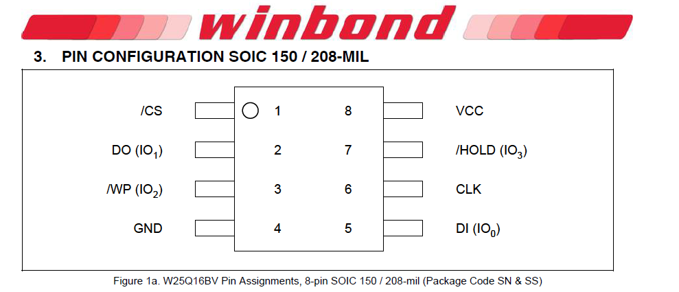
Let's wire this up...
- FT2232 CLK ~ PIN16 to the Flash CLK
- FT2232 SDO ~ PIN17 to the Flash MOSI/DI
- FT2232 SDI ~ PIN18 to the Flash MISO/DO
- FT2232 CS ~ PIN19 to the Flash CS
- FT2232 GND to the Flash GND
- External Power 3V to the Flash VCC
- External Power 3V to the Flash HLD
- External Power 3V to the Flash WP
Let's dump the binary using flashrom...
- flashrom -p ft2232_spi:type=2232H,port=A -r router_firmware_dump.bin
- Notice the settings are specific for the ft2232 because we have multiple channels (port=A)
- This will take a couple of minutes but it's faster than a bus pirate at 20-30 minutes!
andnxor@ubuntu:~/dev/flash_dumps$ flashrom -p ft2232_spi:type=2232H,port=A -r router_firmware_dump.bin
flashrom v0.9.9-r1954 on Linux 4.15.0-46-generic (x86_64)
flashrom is free software, get the source code at https://flashrom.org

Calibrating delay loop... OK.
Found Winbond flash chip "W25Q64.V" (8192 kB, SPI) on ft2232_spi.
Reading flash... done.
Now you have a dump of "whatever" was on the flash. This is where you can use your favorite hex editor (but it probably will NOT help you much) or use binwalk to unpack and analyze it. You will usually end up with an embedded Linux file system with all sorts of fun useful things to explore in the /etc/ directory in terms of configuration files, shadow files with crappy encryption, default accounts and passwords...the world is your oyster. Hack, explore, learn, and break apart every IoT device you own before the machines rise up.
Logic Analyzer
Requires
- Target device with a bus you want to monitor (Serial, I2C, SPI, etc)
- Pulseview / Sigrok (sudo apt-get install sigrok)
- Read the Sigrok Documentation on FT2232 Devices
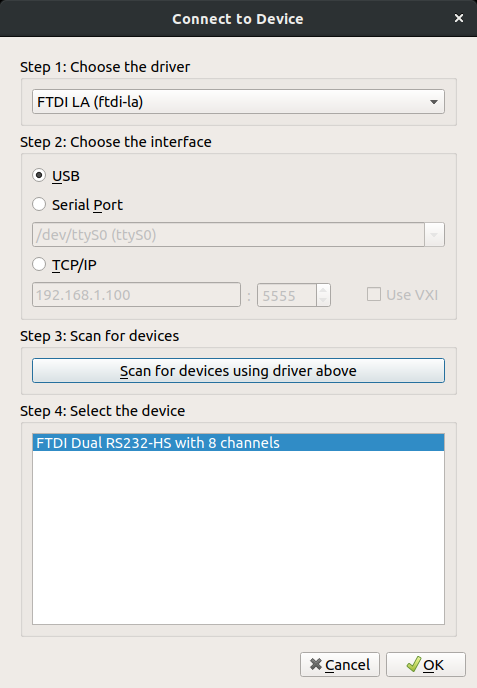
Remember above when I said something about needing a Logic Analyzer? Yeah, it can do that too. Install Sigrok then start it from your application drawer (it will have the name Pulseview). Go to the capture device settings. Use the following...
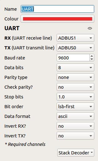
For this demo, we'll use the Classic Bender SAO again. We've connected the FTDI TX (which Pulseview / Sigrok appropriately named ADBUS0) to the Bender RX, FTDI RX (which Pulseview / Sigrok appropriately named ADBUS1) to the Bender TX. We know this is serial UART so let's go ahead and add the UART decoder and set it up...
Let's set the sample rate to 100kHz and run..
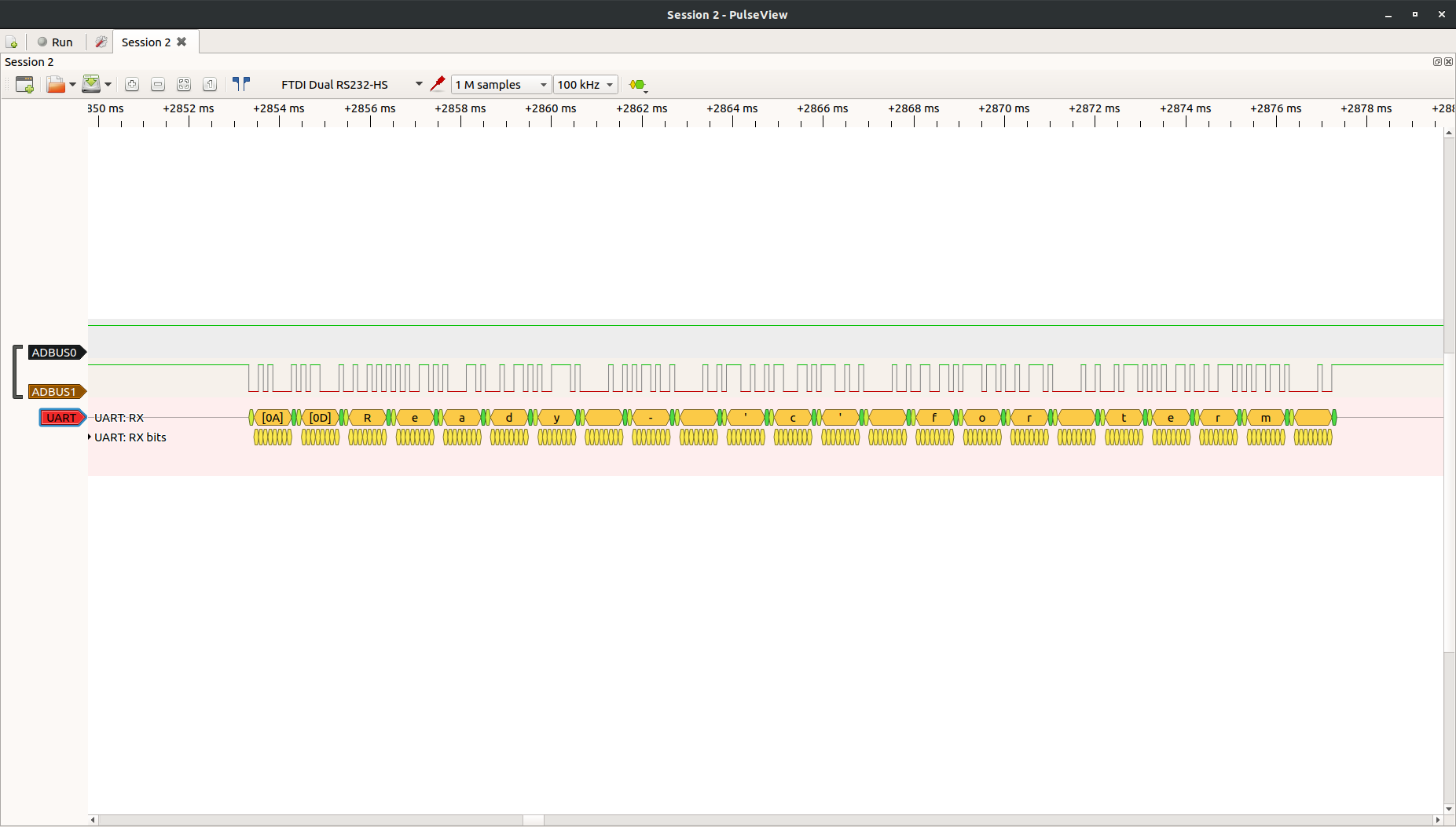
There we go! As you can see in the drop down many decoders are built in to this open source logic analyzer software package. Have fun and learn what's really going across your embedded interfaces.
JTAG Debugging Example
Requires
- Target Device with JTAG Interface
- GDB and OpenOCD
We were getting ready to write another PoC and ran across a perfect example leveraging the FT2232 for OpenOCD debugging on JTAG / SWD (okay, really Hyr0n is up late and getting very tired).
There's really no reason to write up our own when perfectly relevant information exists on the internet. OpenOCD isn't for the faint of heart and has a steep learning curve. But boy howdy is it powerful. You can debug the embedded device in real time, NOP logic, circumvent password checks ;) All of this is possible as long as when the target device was provisioned, that debug wasn't disabled. Zapp is working on a very detailed post describing this, so stay tuned...
Other Fun
At this point you are probably wondering what else can you do with it? Well the reason so many tools exist is that FTDI published well written application design notes and programming guides. There's even Python modules and guides for using them if you aren't comfortable programming in C. Make your own tools or at the very least leverage the hundreds of packages out there that already work with the FT2232.
While you wait for the next post, watch this talk given by Joe Fitz at Securi-Tay 2019 showing many awesome things you can do with this chip.
Discussions
Become a Hackaday.io Member
Create an account to leave a comment. Already have an account? Log In.
So awesome! Probably the best feature of this years badge, IMO.
Are you sure? yes | no